NISSAN ALMERA N16 2003 Electronic Repair Manual
ALMERA N16 2003
NISSAN
NISSAN
https://www.carmanualsonline.info/img/5/57350/w960_57350-0.png
NISSAN ALMERA N16 2003 Electronic Repair Manual
Trending: timing belt, bolt pattern, open hood, rims, instrument panel, steering wheel, radio wire
Page 2431 of 3189
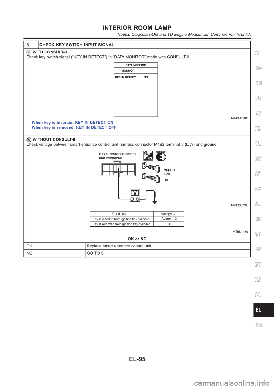
8 CHECK KEY SWITCH INPUT SIGNAL
WITH CONSULT-II
Check key switch signal (“KEY IN DETECT”) in “DATA MONITOR” mode with CONSULT-II.
MKIB0200E
When key is inserted: KEY IN DETECT ON
When key is removed: KEY IN DETECT OFF
WITHOUT CONSULT-II
Check voltage between smart entrance control unit harness connector M193terminal 5 (L/W) and ground.
MKIB0079E
MTBL1430
OK or NG
OK Replace smart entrance control unit.
NG GO TO 9.
GI
MA
EM
LC
EC
FE
CL
MT
AT
AX
SU
BR
ST
RS
BT
HA
SC
IDX
INTERIOR ROOM LAMP
Trouble Diagnoses/QG and YD Engine Models with Common Rail (Cont’d)
EL-95
Page 2432 of 3189
9 CHECK KEY SWITCH (INSERT)
1. Disconnect key switch connector.
2. Check continuity between 1 and 2.
YEL791C
OK or NG
OKCheck the following.
10A fuse [No. 12, located in fuse block (J/B)]
Harness for open or short between key switch and fuse
Harness for open or short between smart entrance control unit and key switch
NG Replace key switch.
INTERIOR ROOM LAMP
Trouble Diagnoses/QG and YD Engine Models with Common Rail (Cont’d)
EL-96
Page 2433 of 3189
DIAGNOSTIC PROCEDURE 2=NJEL0549S05Interior Room Lamp Timer Does Not CancelNJEL0549S0501
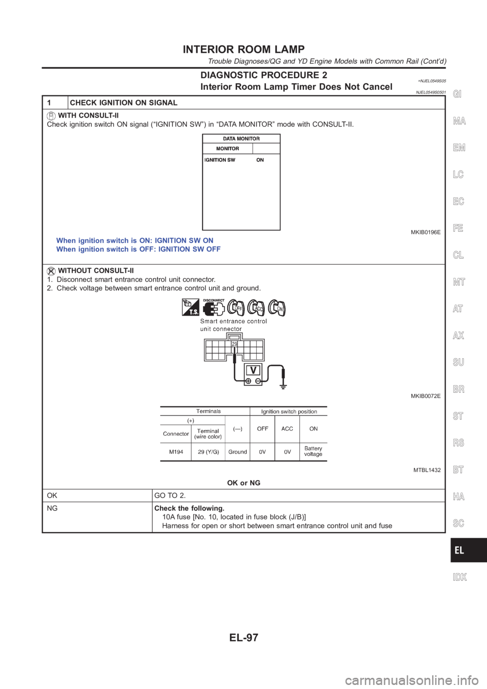
1 CHECK IGNITION ON SIGNAL
WITH CONSULT-II
Check ignition switch ON signal (“IGNITION SW”) in “DATA MONITOR” mode with CONSULT-II.
MKIB0196E
When ignition switch is ON: IGNITION SW ON
When ignition switch is OFF: IGNITION SW OFF
WITHOUT CONSULT-II
1. Disconnect smart entrance control unit connector.
2. Check voltage between smart entrance control unit and ground.
MKIB0072E
MTBL1432
OK or NG
OK GO TO 2.
NGCheck the following.
10A fuse [No. 10, located in fuse block (J/B)]
Harness for open or short between smart entrance control unit and fuse
GI
MA
EM
LC
EC
FE
CL
MT
AT
AX
SU
BR
ST
RS
BT
HA
SC
IDX
INTERIOR ROOM LAMP
Trouble Diagnoses/QG and YD Engine Models with Common Rail (Cont’d)
EL-97
Page 2434 of 3189
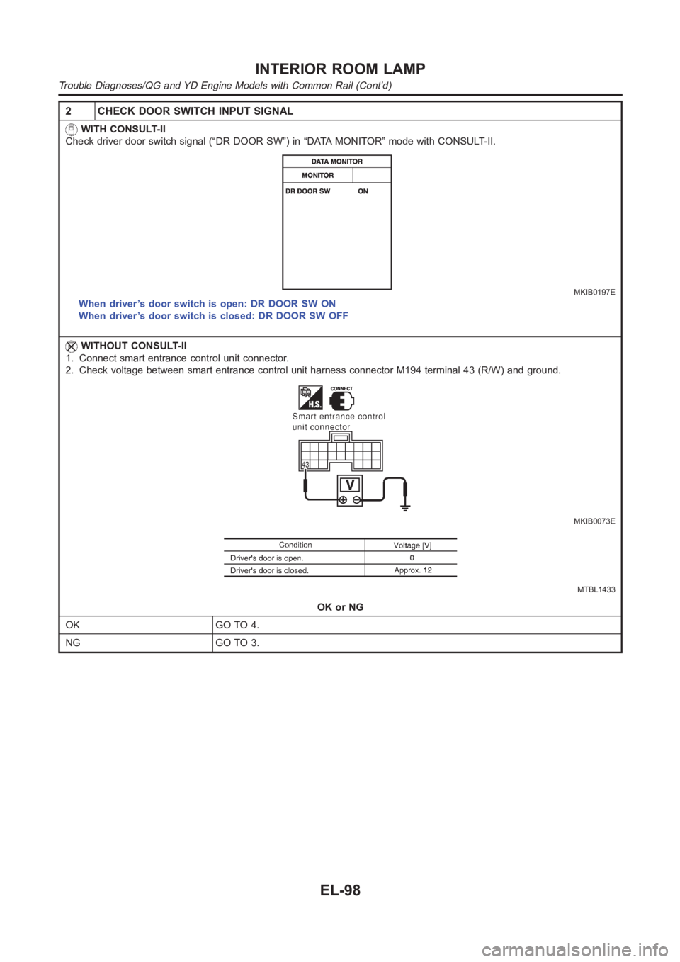
2 CHECK DOOR SWITCH INPUT SIGNAL
WITH CONSULT-II
Check driver door switch signal (“DR DOOR SW”) in “DATA MONITOR” mode with CONSULT-II.
MKIB0197E
When driver’s door switch is open: DR DOOR SW ON
When driver’s door switch is closed: DR DOOR SW OFF
WITHOUT CONSULT-II
1. Connect smart entrance control unit connector.
2. Check voltage between smart entrance control unit harness connector M194 terminal 43 (R/W) and ground.
MKIB0073E
MTBL1433
OK or NG
OK GO TO 4.
NG GO TO 3.
INTERIOR ROOM LAMP
Trouble Diagnoses/QG and YD Engine Models with Common Rail (Cont’d)
EL-98
Page 2435 of 3189
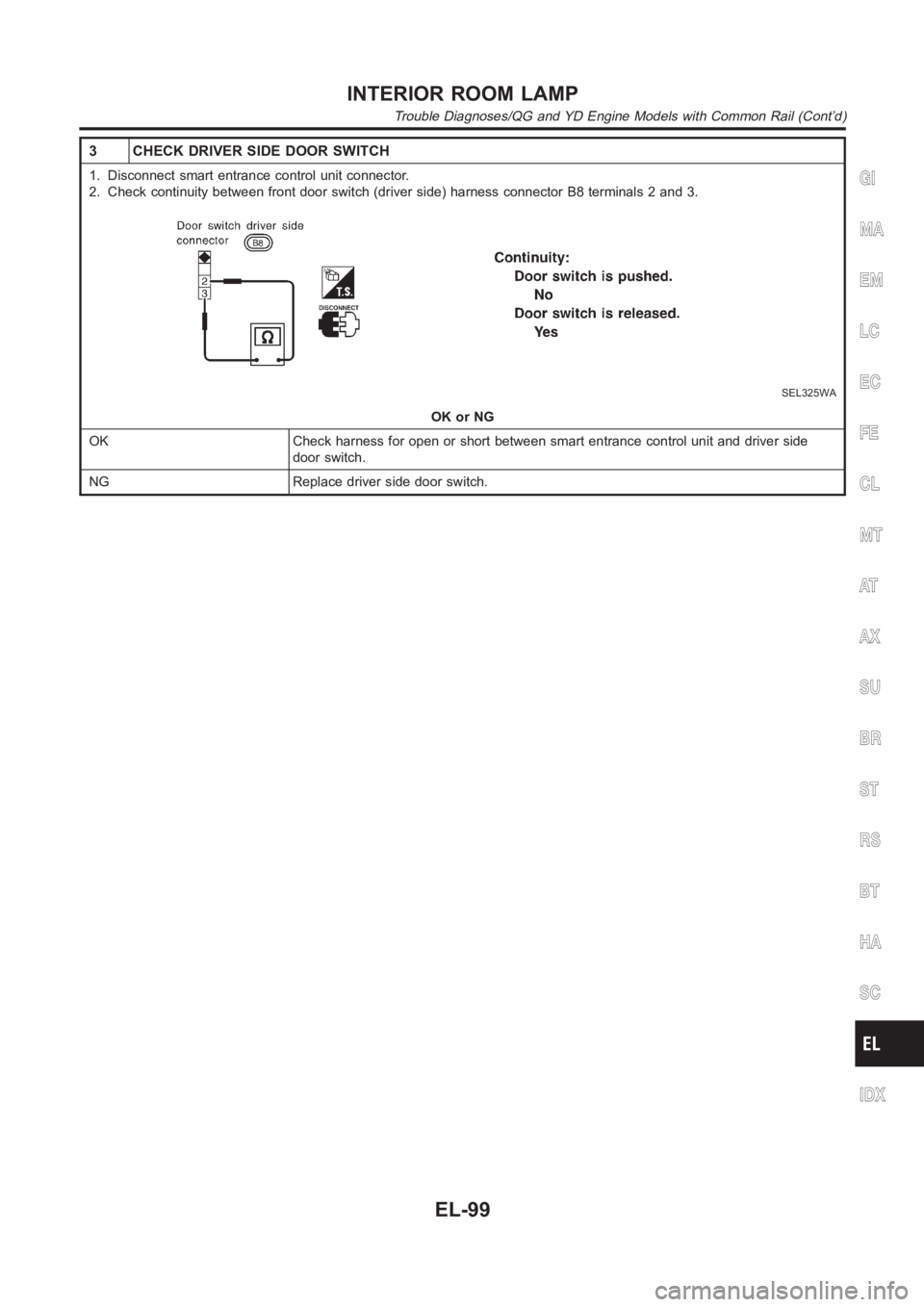
3 CHECK DRIVER SIDE DOOR SWITCH
1. Disconnect smart entrance control unit connector.
2. Check continuity between front door switch (driver side) harness connector B8 terminals 2 and 3.
SEL325WA
OK or NG
OK Check harness for open or short between smart entrance control unit and driver side
door switch.
NG Replace driver side door switch.
GI
MA
EM
LC
EC
FE
CL
MT
AT
AX
SU
BR
ST
RS
BT
HA
SC
IDX
INTERIOR ROOM LAMP
Trouble Diagnoses/QG and YD Engine Models with Common Rail (Cont’d)
EL-99
Page 2436 of 3189
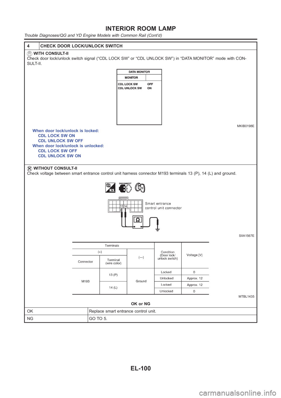
4 CHECK DOOR LOCK/UNLOCK SWITCH
WITH CONSULT-II
Check door lock/unlock switch signal (“CDL LOCK SW” or “CDL UNLOCK SW”) in “DATA MONITOR” mode with CON-
SULT-II.
MKIB0198E
When door lock/unlock is locked:
CDL LOCK SW ON
CDL UNLOCK SW OFF
When door lock/unlock is unlocked:
CDL LOCK SW OFF
CDL UNLOCK SW ON
WITHOUT CONSULT-II
Check voltage between smart entrance control unit harness connector M193terminals 13 (P), 14 (L) and ground.
SIIA1567E
MTBL1435
OK or NG
OK Replace smart entrance control unit.
NG GO TO 5.
INTERIOR ROOM LAMP
Trouble Diagnoses/QG and YD Engine Models with Common Rail (Cont’d)
EL-100
Page 2437 of 3189
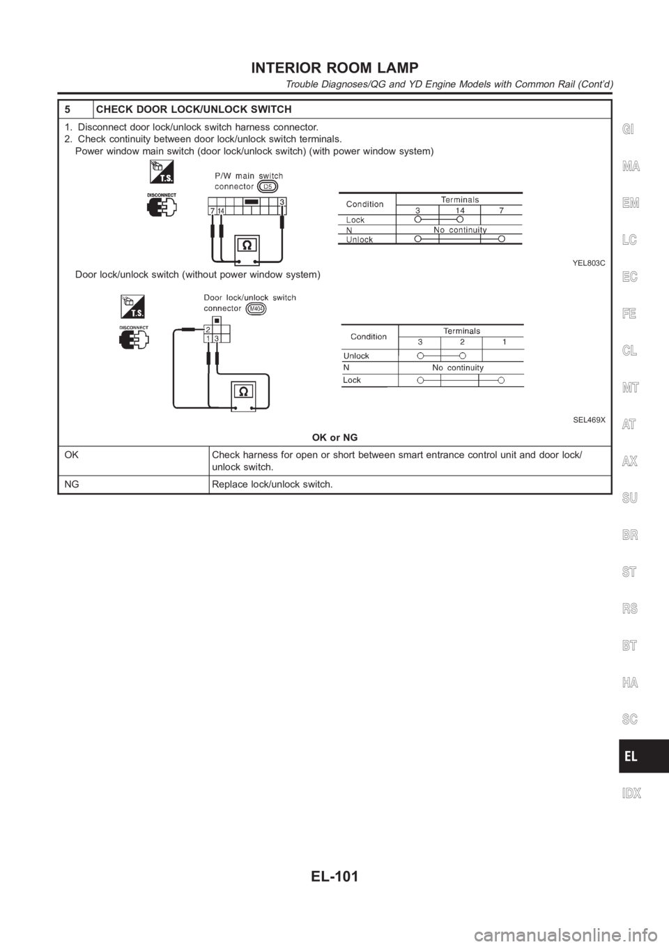
5 CHECK DOOR LOCK/UNLOCK SWITCH
1. Disconnect door lock/unlock switch harness connector.
2. Check continuity between door lock/unlock switch terminals.
Power window main switch (door lock/unlock switch) (with power window system)
YEL803C
Door lock/unlock switch (without power window system)
SEL469X
OK or NG
OK Check harness for open or short between smart entrance control unit and door lock/
unlock switch.
NG Replace lock/unlock switch.
GI
MA
EM
LC
EC
FE
CL
MT
AT
AX
SU
BR
ST
RS
BT
HA
SC
IDX
INTERIOR ROOM LAMP
Trouble Diagnoses/QG and YD Engine Models with Common Rail (Cont’d)
EL-101
Page 2438 of 3189
Trouble Diagnoses/YD Engine Models without
Common Rail and K9K Engine Models
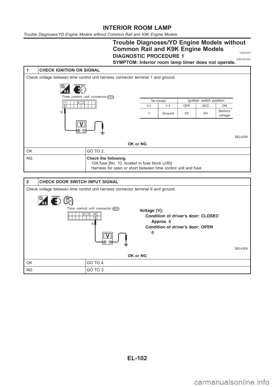
=NJEL0437DIAGNOSTIC PROCEDURE 1NJEL0437S01SYMPTOM: Interior room lamp timer does not operate.
1 CHECK IGNITION ON SIGNAL
Check voltage between time control unit harness connector terminal 1 and ground.
SEL429X
OK or NG
OK GO TO 2.
NGCheck the following.
10A fuse [No. 10, located in fuse block (J/B)]
Harness for open or short between time control unit and fuse
2 CHECK DOOR SWITCH INPUT SIGNAL
Check voltage between time control unit harness connector terminal 6 and ground.
SEL430X
OK or NG
OK GO TO 4.
NG GO TO 3.
INTERIOR ROOM LAMP
Trouble Diagnoses/YD Engine Models without Common Rail and K9K Engine Models
EL-102
Page 2439 of 3189
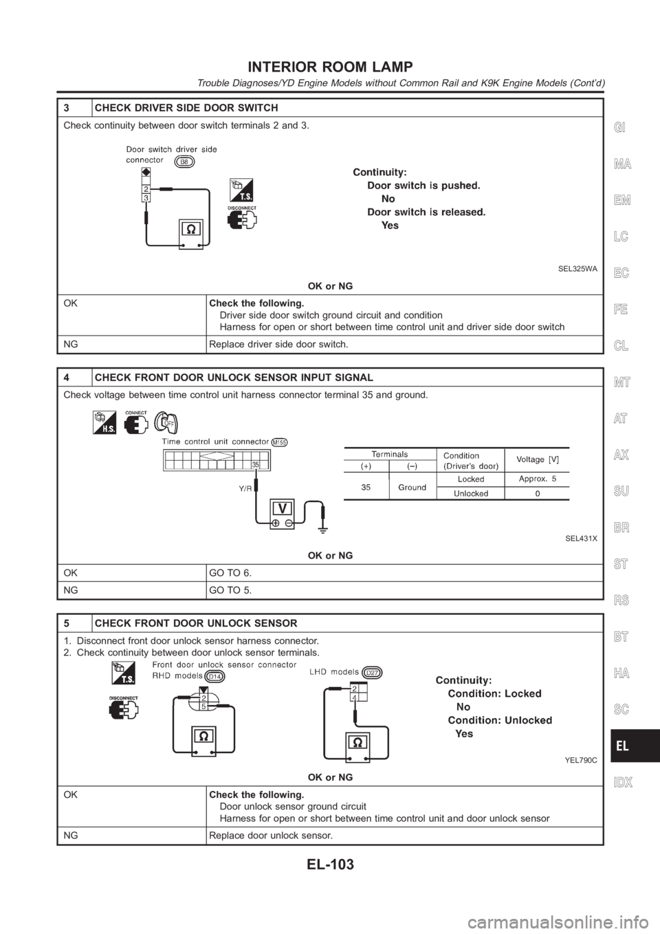
3 CHECK DRIVER SIDE DOOR SWITCH
Check continuity between door switch terminals 2 and 3.
SEL325WA
OK or NG
OKCheck the following.
Driver side door switch ground circuit and condition
Harness for open or short between time control unit and driver side door switch
NG Replace driver side door switch.
4 CHECK FRONT DOOR UNLOCK SENSOR INPUT SIGNAL
Check voltage between time control unit harness connector terminal 35 andground.
SEL431X
OK or NG
OK GO TO 6.
NG GO TO 5.
5 CHECK FRONT DOOR UNLOCK SENSOR
1. Disconnect front door unlock sensor harness connector.
2. Check continuity between door unlock sensor terminals.
YEL790C
OK or NG
OKCheck the following.
Door unlock sensor ground circuit
Harness for open or short between time control unit and door unlock sensor
NG Replace door unlock sensor.
GI
MA
EM
LC
EC
FE
CL
MT
AT
AX
SU
BR
ST
RS
BT
HA
SC
IDX
INTERIOR ROOM LAMP
Trouble Diagnoses/YD Engine Models without Common Rail and K9K Engine Models (Cont’d)
EL-103
Page 2440 of 3189
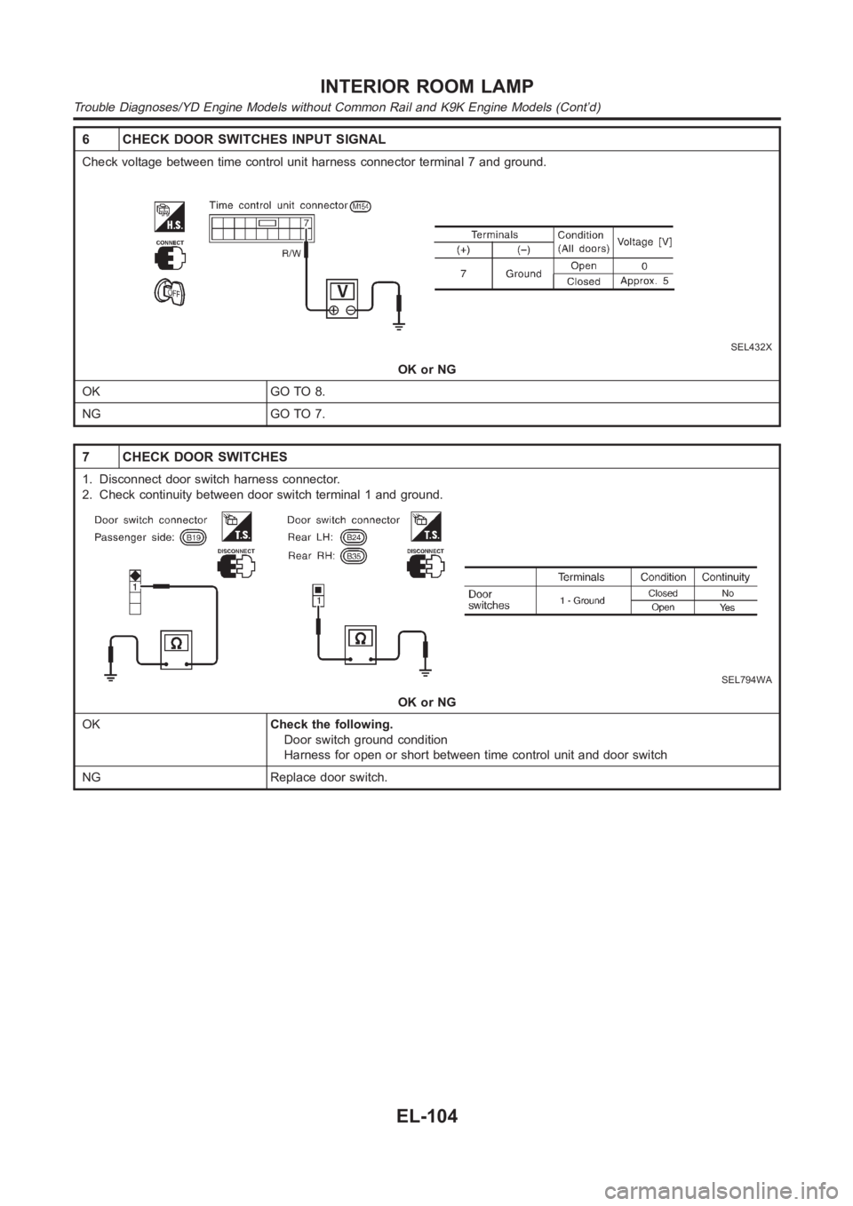
6 CHECK DOOR SWITCHES INPUT SIGNAL
Check voltage between time control unit harness connector terminal 7 and ground.
SEL432X
OK or NG
OK GO TO 8.
NG GO TO 7.
7 CHECK DOOR SWITCHES
1. Disconnect door switch harness connector.
2. Check continuity between door switch terminal 1 and ground.
SEL794WA
OK or NG
OKCheck the following.
Door switch ground condition
Harness for open or short between time control unit and door switch
NG Replace door switch.
INTERIOR ROOM LAMP
Trouble Diagnoses/YD Engine Models without Common Rail and K9K Engine Models (Cont’d)
EL-104
Trending: hood release, satellite navigation display, Horn, Idler pulley, iat, GEAR, Pulley
![NISSAN ALMERA N16 2003 Electronic Repair Manual 9 CHECK KEY SWITCH (INSERT)
1. Disconnect key switch connector.
2. Check continuity between 1 and 2.
YEL791C
OK or NG
OKCheck the following.
10A fuse [No. 12, located in fuse block (J/B)]
Harness for NISSAN ALMERA N16 2003 Electronic Repair Manual 9 CHECK KEY SWITCH (INSERT)
1. Disconnect key switch connector.
2. Check continuity between 1 and 2.
YEL791C
OK or NG
OKCheck the following.
10A fuse [No. 12, located in fuse block (J/B)]
Harness for](/img/5/57350/w960_57350-2431.png)
