NISSAN ALMERA N16 2003 Electronic Repair Manual
Manufacturer: NISSAN, Model Year: 2003, Model line: ALMERA N16, Model: NISSAN ALMERA N16 2003Pages: 3189, PDF Size: 54.76 MB
Page 2791 of 3189
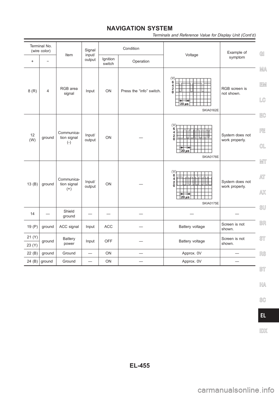
Terminal No.
(wire color)
ItemSignal
input/
outputCondition
VoltageExample of
symptom
+−Ignition
switchOperation
8(R) 4RGB area
signalInput ON Press the “info” switch.
SKIA0162E
RGB screen is
not shown.
12
(W)groundCommunica-
tion signal
(-)Input/
outputON —
SKIA0176E
System does not
work properly.
13 (B) groundCommunica-
tion signal
(+)Input/
outputON —
SKIA0175E
System does not
work properly.
14 —Shield
ground—— — — —
19 (P) ground ACC signal Input ACC — Battery voltageScreen is not
shown.
21 (Y)
groundBattery
powerInput OFF — Battery voltageScreen is not
shown.
23 (Y)
22 (B) ground Ground — ON — Approx. 0V —
24 (B) ground Ground — ON — Approx. 0V —
GI
MA
EM
LC
EC
FE
CL
MT
AT
AX
SU
BR
ST
RS
BT
HA
SC
IDX
NAVIGATION SYSTEM
Terminals and Reference Value for Display Unit (Cont’d)
EL-455
Page 2792 of 3189
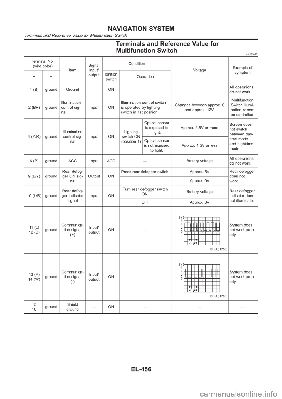
Terminals and Reference Value for
Multifunction Switch
=NJEL0601
Terminal No.
(wire color)
ItemSignal
input/
outputCondition
VoltageExample of
symptom
+−Ignition
switchOperation
1 (B) ground Ground — ON — —All operations
do not work.
2 (BR) groundIllumination
control sig-
nalInput ONIllumination control switch
is operated by lighting
switch in 1st position.Changes between approx. 0
and approx. 12V.Multifunction
Switch illumi-
nation cannot
be controlled.
4 (Y/R) groundIllumination
control sig-
nalInput ONLighting
switch ON
(position 1)Optical sensor
is exposed to
light.Approx. 3.5V or moreScreen does
not switch
between day-
time mode
and nighttime
mode. Optical sensor
is not exposed
to light.Approx. 1.5V or less
6 (P) ground ACC Input ACC — Battery voltageAll operations
do not work.
9 (L/Y) groundRear defog-
ger ON sig-
nalOutput ONPress rear defogger switch. Approx. 5VRear defogger
does not
work. — Approx. 0V
10 (L/R) groundRear defog-
ger indicator
signalInput ONTurn rear defogger switch
ON.Battery voltageRear defogger
indicator does
not illuminate.
OFF Approx. 0V
11 (L)
12 (B)groundCommunica-
tion signal
(+)Input/
outputON —
SKIA0175E
System does
not work prop-
erly.
13 (P)
14 (W)groundCommunica-
tion signal
(-)Input/
outputON —
SKIA0176E
System does
not work prop-
erly.
15
16groundShield
ground—ON — — —
NAVIGATION SYSTEM
Terminals and Reference Value for Multifunction Switch
EL-456
Page 2793 of 3189
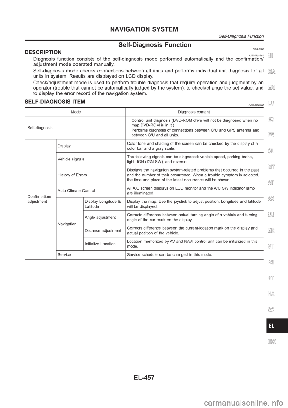
Self-Diagnosis FunctionNJEL0602DESCRIPTIONNJEL0602S01Diagnosis function consists of the self-diagnosis mode performed automatically and the confirmation/
adjustment mode operated manually.
Self-diagnosis mode checks connections between all units and performs individual unit diagnosis for all
units in system. Results are displayed on LCD display.
Check/adjustment mode is used to perform trouble diagnosis that require operation and judgment by an
operator (trouble that cannot be automatically judged by the system), to check/change the set value, and
to display the error record of the navigation system.
SELF-DIAGNOSIS ITEMNJEL0602S02
Mode Diagnosis content
Self-diagnosisControl unit diagnosis (DVD-ROM drive will not be diagnosed when no
map DVD-ROM is in it.)
Performs diagnosis of connections between C/U and GPS antenna and
between C/U and all units.
Confirmation/
adjustmentDisplayColor tone and shading of the screen can be checked by the display of a
color bar and a gray scale.
Vehicle signalsThe following signals can be diagnosed: vehicle speed, parking brake,
light, IGN (IGN SW), and reverse.
History of ErrorsDisplays the navigation system-related problems that occurred in the past
and the number of their occurrence. When a trouble symptom is selected,
the time and place of the latest occurrence will be shown.
Auto Climate ControlAll A/C screen displays on LCD monitor and the A/C SW indicator lamp
are illuminated.
NavigationDisplay Longitude &
LatitudeDisplay the map. Use the joystick to adjust position. Longitude and latitude
will be displayed.
Angle adjustmentCorrects difference between actual turning angle of a vehicle and turning
angle of the car mark on the display.
Distance adjustmentCorrects difference between the current-location mark on the display and
actual position of the vehicle.
Initialize LocationLocation memorized by AV and NAVI control unit can be initialized in this
mode.
Service Service schedule can be changed in this mode.
GI
MA
EM
LC
EC
FE
CL
MT
AT
AX
SU
BR
ST
RS
BT
HA
SC
IDX
NAVIGATION SYSTEM
Self-Diagnosis Function
EL-457
Page 2794 of 3189
YEL832D
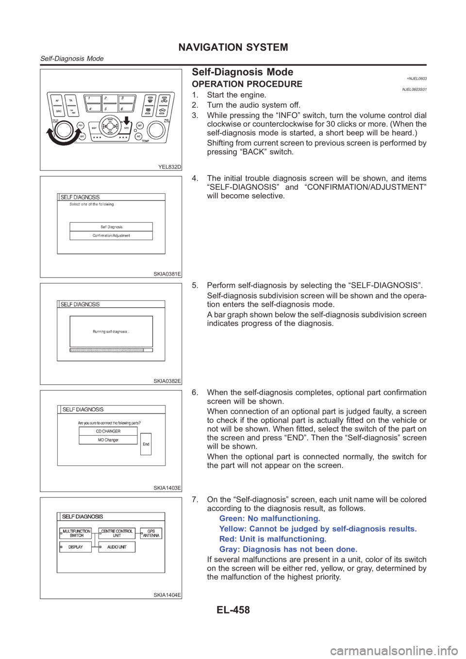
Self-Diagnosis Mode=NJEL0603OPERATION PROCEDURENJEL0603S011. Start the engine.
2. Turn the audio system off.
3. While pressing the “INFO” switch, turn the volume control dial
clockwise or counterclockwise for 30 clicks or more. (When the
self-diagnosis mode is started, a short beep will be heard.)
Shifting from current screen to previous screen is performed by
pressing “BACK” switch.
SKIA0381E
4. The initial trouble diagnosis screen will be shown, and items
“SELF-DIAGNOSIS” and “CONFIRMATION/ADJUSTMENT”
will become selective.
SKIA0382E
5. Perform self-diagnosis by selecting the “SELF-DIAGNOSIS”.
Self-diagnosis subdivision screen will be shown and the opera-
tion enters the self-diagnosis mode.
A bar graph shown below the self-diagnosis subdivision screen
indicates progress of the diagnosis.
SKIA1403E
6. When the self-diagnosis completes, optional part confirmation
screen will be shown.
When connection of an optional part is judged faulty, a screen
to check if the optional part is actually fitted on the vehicle or
not will be shown. When fitted, select the switch of the part on
the screen and press “END”. Then the “Self-diagnosis” screen
will be shown.
When the optional part is connected normally, the switch for
the part will not appear on the screen.
SKIA1404E
7. On the “Self-diagnosis” screen, each unit name will be colored
according to the diagnosis result, as follows.
Green: No malfunctioning.
Yellow: Cannot be judged by self-diagnosis results.
Red: Unit is malfunctioning.
Gray: Diagnosis has not been done.
If several malfunctions are present in a unit, color of its switch
on the screen will be either red, yellow, or gray, determined by
the malfunction of the highest priority.
NAVIGATION SYSTEM
Self-Diagnosis Mode
EL-458
Page 2795 of 3189

SKIA1516E
8. Select a switch on the “Self-diagnosis” screen and comments
for the diagnosis results will be shown.
When the switch is green, the following comment will be
shown. “Self-diagnosis was successful. Further diagnosis and
adjustments are recommended. Follow the “confirmation and
adjustments” menu or refer to the service manual”.
When the switch is yellow, the following comment will be
shown. “Connection to the following unit is abnormal. See the
service manual for further details”.
When the switch is red, the following comment will be shown.
“Center Control Unit is abnormal”.
When the switch is gray, the following comment will be shown.
“Self-diagnosis for DVD-ROM DRIVER of NAVI was not con-
ducted because no DVD-ROM was available”.
GI
MA
EM
LC
EC
FE
CL
MT
AT
AX
SU
BR
ST
RS
BT
HA
SC
IDX
NAVIGATION SYSTEM
Self-Diagnosis Mode (Cont’d)
EL-459
Page 2796 of 3189
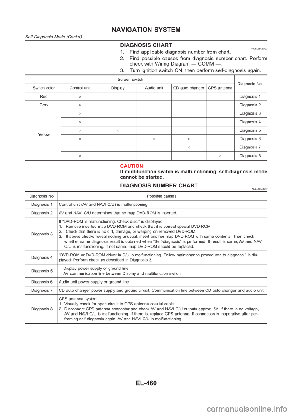
DIAGNOSIS CHART=NJEL0603S021. Find applicable diagnosis number from chart.
2. Find possible causes from diagnosis number chart. Perform
check with Wiring Diagram — COMM —.
3. Turn ignition switch ON, then perform self-diagnosis again.
Screen switch
Diagnosis No.
Switch color Control unit Display Audio unit CD auto changer GPS antenna
Red×Diagnosis 1
Gray×Diagnosis 2
Yellow×Diagnosis 3
×Diagnosis 4
××Diagnosis 5
×××Diagnosis 6
×Diagnosis 7
××Diagnosis 8
CAUTION:
If multifunction switch is malfunctioning, self-diagnosis mode
cannot be started.
DIAGNOSIS NUMBER CHARTNJEL0603S03
Diagnosis No. Possible causes
Diagnosis 1 Control unit (AV and NAVI C/U) is malfunctioning.
Diagnosis 2 AV and NAVI C/U determines that no map DVD-ROM is inserted.
Diagnosis 3If “DVD-ROM is malfunctioning. Check disc.” is displayed:
1. Remove inserted map DVD-ROM and check that it is correct special DVD-ROM.
2. Check that there is no dirt, damage, or warping on removed DVD-ROM.
3. If above checks reveal nothing unusual, insert another map DVD-ROM withsame contents. Then check
whether same diagnosis result is obtained when “Self-diagnosis” is performed. If result is same, AV and NAVI
C/U is malfunctioning. If not same, map DVD-ROM should be replaced.
Diagnosis 4“DVD-ROM or DVD-ROM driver in C/U is malfunctioning. Follow maintenance procedures to diagnose.” is dis-
played: Perform check as described in Diagnosis 3.
Diagnosis 5Display power supply or ground line
AV communication line between Display and multifunction switch
Diagnosis 6 Audio unit power supply or ground line
Diagnosis 7 CD auto changer power supply and ground circuit, Communication line between CD auto changer and audio unit
Diagnosis 8GPS antenna system
1. Visually check for open circuit in GPS antenna coaxial cable.
2. Disconnect GPS antenna connector and check AV and NAVI C/U outputs approx. 5V. If there is no voltage,
AV and NAVI C/U is malfunctioning. If there is, replace GPS antenna. If connection is inoperative after per-
forming self-diagnosis again, AV and NAVI C/U is malfunctioning.
NAVIGATION SYSTEM
Self-Diagnosis Mode (Cont’d)
EL-460
Page 2797 of 3189
YEL832D
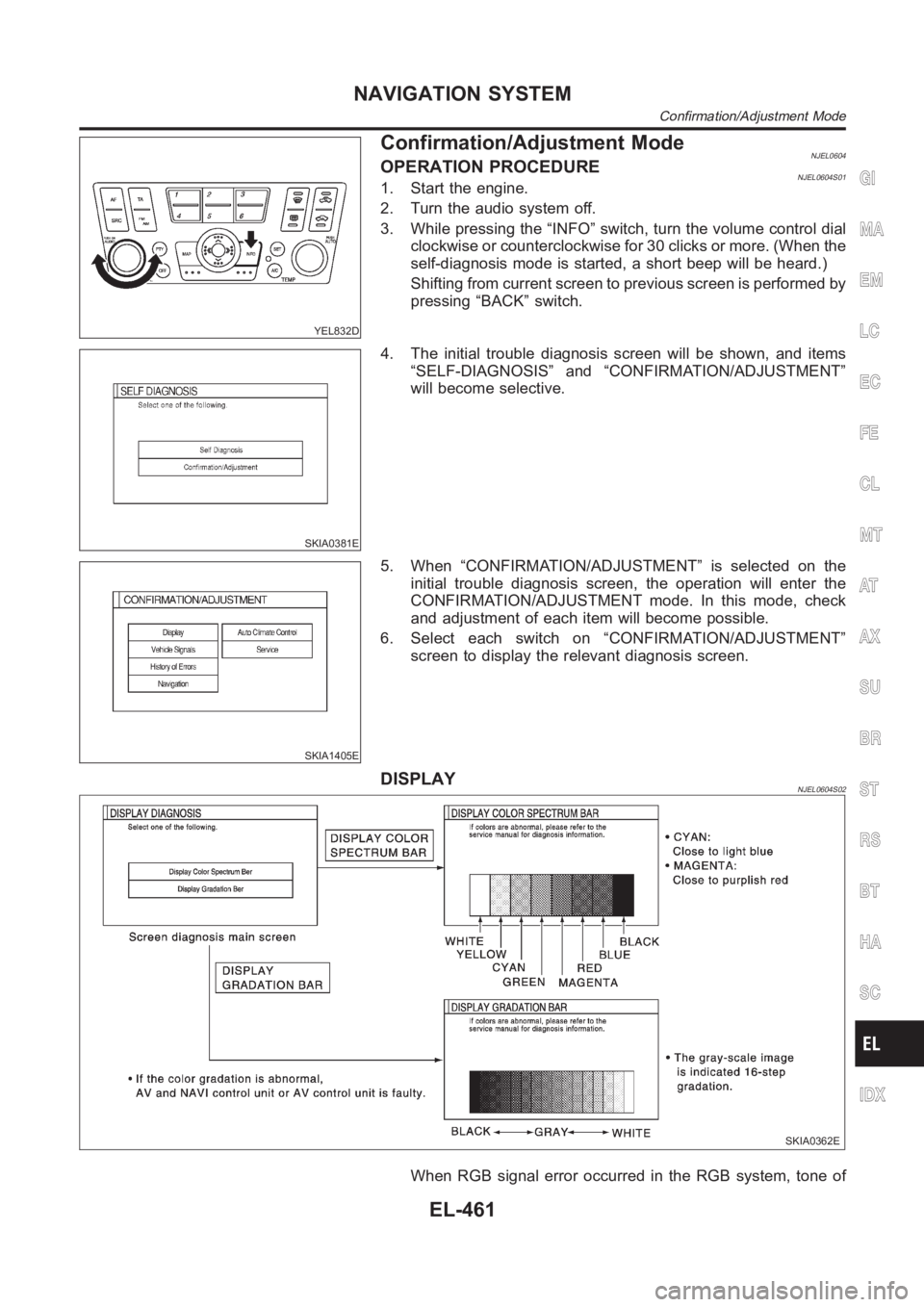
Confirmation/Adjustment ModeNJEL0604OPERATION PROCEDURENJEL0604S011. Start the engine.
2. Turn the audio system off.
3. While pressing the “INFO” switch, turn the volume control dial
clockwise or counterclockwise for 30 clicks or more. (When the
self-diagnosis mode is started, a short beep will be heard.)
Shifting from current screen to previous screen is performed by
pressing “BACK” switch.
SKIA0381E
4. The initial trouble diagnosis screen will be shown, and items
“SELF-DIAGNOSIS” and “CONFIRMATION/ADJUSTMENT”
will become selective.
SKIA1405E
5. When “CONFIRMATION/ADJUSTMENT” is selected on the
initial trouble diagnosis screen, the operation will enter the
CONFIRMATION/ADJUSTMENT mode. In this mode, check
and adjustment of each item will become possible.
6. Select each switch on “CONFIRMATION/ADJUSTMENT”
screen to display the relevant diagnosis screen.
DISPLAYNJEL0604S02
SKIA0362E
When RGB signal error occurred in the RGB system, tone of
GI
MA
EM
LC
EC
FE
CL
MT
AT
AX
SU
BR
ST
RS
BT
HA
SC
IDX
NAVIGATION SYSTEM
Confirmation/Adjustment Mode
EL-461
Page 2798 of 3189
the color bar will change as follows.
R (red) signal error: Screen looks bluish
G (green) signal error: Screen looks yellowish
B (blue) signal error: Screen looks reddish
When the color of the screen looks unusual, EL-477, Color of
RGB Image Is Not Proper.
SKIA1406E
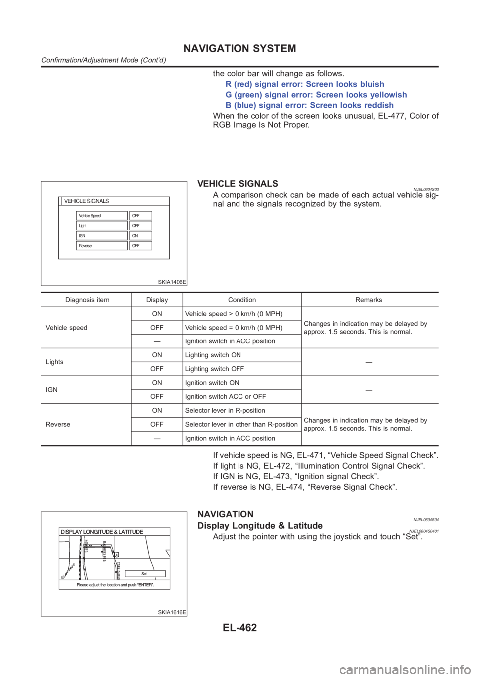
VEHICLE SIGNALSNJEL0604S03A comparison check can be made of each actual vehicle sig-
nal and the signals recognized by the system.
Diagnosis item Display Condition Remarks
Vehicle speedON Vehicle speed > 0 km/h (0 MPH)
Changes in indication may be delayed by
approx. 1.5 seconds. This is normal. OFF Vehicle speed = 0 km/h (0 MPH)
— Ignition switch in ACC position
LightsON Lighting switch ON
—
OFF Lighting switch OFF
IGNON Ignition switch ON
—
OFF Ignition switch ACC or OFF
ReverseON Selector lever in R-position
Changes in indication may be delayed by
approx. 1.5 seconds. This is normal. OFF Selector lever in other than R-position
— Ignition switch in ACC position
If vehicle speed is NG, EL-471, “Vehicle Speed Signal Check”.
If light is NG, EL-472, “Illumination Control Signal Check”.
If IGN is NG, EL-473, “Ignition signal Check”.
If reverse is NG, EL-474, “Reverse Signal Check”.
SKIA1616E
NAVIGATIONNJEL0604S04Display Longitude & LatitudeNJEL0604S0401Adjust the pointer with using the joystick and touch “Set”.
NAVIGATION SYSTEM
Confirmation/Adjustment Mode (Cont’d)
EL-462
Page 2799 of 3189
SKIA1617E
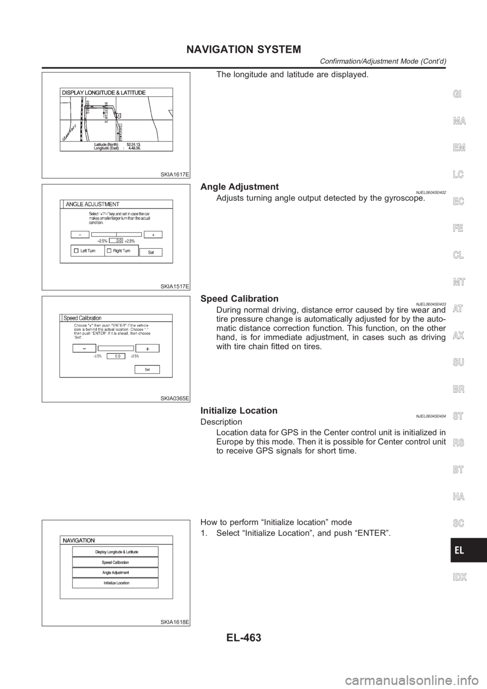
The longitude and latitude are displayed.
SKIA1517E
Angle AdjustmentNJEL0604S0402Adjusts turning angle output detected by the gyroscope.
SKIA0365E
Speed CalibrationNJEL0604S0403During normal driving, distance error caused by tire wear and
tire pressure change is automatically adjusted for by the auto-
matic distance correction function. This function, on the other
hand, is for immediate adjustment, in cases such as driving
with tire chain fitted on tires.
Initialize LocationNJEL0604S0404Description
Location data for GPS in the Center control unit is initialized in
Europe by this mode. Then it is possible for Center control unit
to receive GPS signals for short time.
SKIA1618E
How to perform “Initialize location” mode
1. Select “Initialize Location”, and push “ENTER”.
GI
MA
EM
LC
EC
FE
CL
MT
AT
AX
SU
BR
ST
RS
BT
HA
SC
IDX
NAVIGATION SYSTEM
Confirmation/Adjustment Mode (Cont’d)
EL-463
Page 2800 of 3189
SKIA1619E
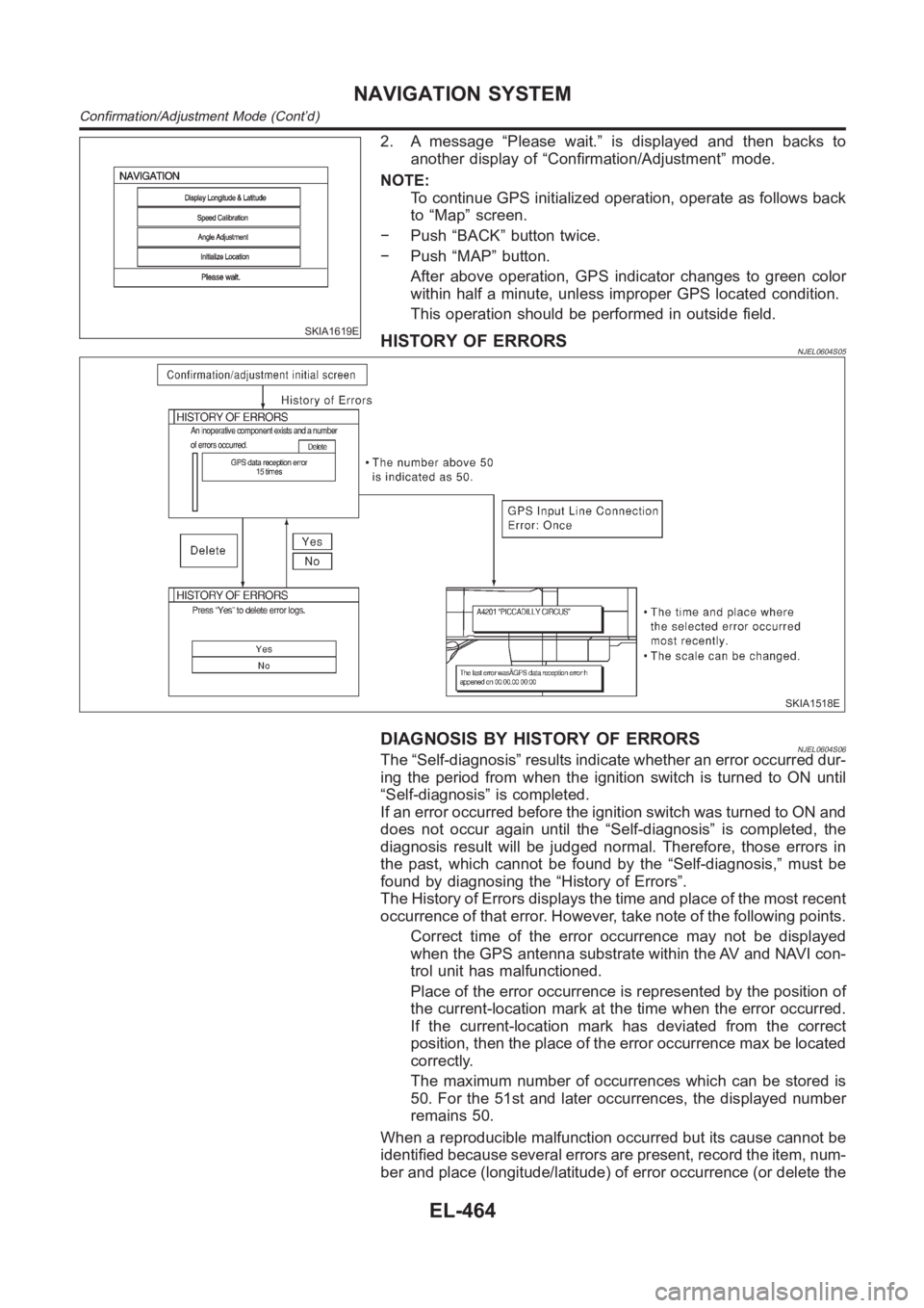
2. A message “Please wait.” is displayed and then backs to
another display of “Confirmation/Adjustment” mode.
NOTE:
To continue GPS initialized operation, operate as follows back
to “Map” screen.
− Push “BACK” button twice.
− Push “MAP” button.
After above operation, GPS indicator changes to green color
within half a minute, unless improper GPS located condition.
This operation should be performed in outside field.
HISTORY OF ERRORSNJEL0604S05
SKIA1518E
DIAGNOSIS BY HISTORY OF ERRORSNJEL0604S06The “Self-diagnosis” results indicate whether an error occurred dur-
ing the period from when the ignition switch is turned to ON until
“Self-diagnosis” is completed.
If an error occurred before the ignition switch was turned to ON and
does not occur again until the “Self-diagnosis” is completed, the
diagnosis result will be judged normal. Therefore, those errors in
the past, which cannot be found by the “Self-diagnosis,” must be
found by diagnosing the “History of Errors”.
The History of Errors displays the time and place of the most recent
occurrence of that error. However, take note of the following points.
Correct time of the error occurrence may not be displayed
when the GPS antenna substrate within the AV and NAVI con-
trol unit has malfunctioned.
Place of the error occurrence is represented by the position of
the current-location mark at the time when the error occurred.
If the current-location mark has deviated from the correct
position, then the place of the error occurrence max be located
correctly.
The maximum number of occurrences which can be stored is
50. For the 51st and later occurrences, the displayed number
remains 50.
When a reproducible malfunction occurred but its cause cannot be
identified because several errors are present, record the item, num-
ber and place (longitude/latitude) of error occurrence (or delete the
NAVIGATION SYSTEM
Confirmation/Adjustment Mode (Cont’d)
EL-464