NISSAN ALMERA N16 2003 Electronic Repair Manual
Manufacturer: NISSAN, Model Year: 2003, Model line: ALMERA N16, Model: NISSAN ALMERA N16 2003Pages: 3189, PDF Size: 54.76 MB
Page 2801 of 3189
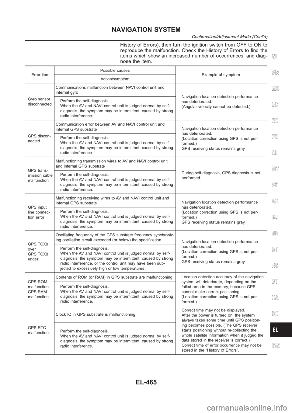
History of Errors), then turn the ignition switch from OFF to ON to
reproduce the malfunction. Check the History of Errors to find the
items which show an increased number of occurrences, and diag-
nose the item.
Error itemPossible causes
Example of symptom
Action/symptom
Gyro sensor
disconnectedCommunications malfunction between NAVI control unit and
internal gyro
Navigation location detection performance
has deteriorated.
(Angular velocity cannot be detected.) Perform the self-diagnosis.
When the AV and NAVI control unit is judged normal by self-
diagnosis, the symptom may be intermittent, caused by strong
radio interference.
GPS discon-
nectedCommunication error between AV and NAVI control unit and
internal GPS substrateNavigation location detection performance
has deteriorated.
(Location correction using GPS is not per-
formed.)
GPS receiving status remains gray. Perform the self-diagnosis.
When the AV and NAVI control unit is judged normal by self-
diagnosis, the symptom may be intermittent, caused by strong
radio interference.
GPS trans-
mission cable
malfunctionMalfunctioning transmission wires to AV and NAVI control unit
and internal GPS substrate
During self-diagnosis, GPS diagnosis is not
performed. Perform the self-diagnosis.
When the AV and NAVI control unit is judged normal by self-
diagnosis, the symptom may be intermittent, caused by strong
radio interference.
GPS input
line connec-
tion errorMalfunctioning receiving wires to AV and NAVI control unit and
internal GPS substrateNavigation location detection performance
has deteriorated.
(Location correction using GPS is not per-
formed.)
GPS receiving status remains gray. Perform the self-diagnosis.
When the AV and NAVI control unit is judged normal by self-
diagnosis, the symptom may be intermittent, caused by strong
radio interference.
GPS TCX0
over
GPS TCX0
underOscillating frequency of the GPS substrate frequency synchroniz-
ing oscillation circuit exceeded (or below) the specification
Navigation location detection performance
has deteriorated.
(Location correction using GPS is not per-
formed.)
GPS receiving status remains gray. Perform the self-diagnosis.
When the AV and NAVI control unit is judged normal by self-
diagnosis, the symptom may be intermittent, caused by strong
radio interference, or the control unit may have been sub-
jected to excessively high or low temperatures.
GPS ROM
malfunction
GPS RAM
malfunctionContents of ROM (or RAM) in GPS substrate are malfunctioning.Location detection accuracy of the navigation
system will deteriorate, depending on the
failed area in the memory, because GPS
cannot make correct positioning.
(Location correction using GPS is not per-
formed.) Perform the self-diagnosis.
When the AV and NAVI control unit is judged normal by self-
diagnosis, the symptom may be intermittent, caused by strong
radio interference.
GPS RTC
malfunctionClock IC in GPS substrate is malfunctioning.Correct time may not be displayed.
After the power is turned on, the system
always takes some time until GPS position-
ing becomes possible. (The GPS receiver
starts positioning without re-collecting the
whole satellite information when it judged the
data stored in the receiver is correct.)
Correct time of error occurrence may not be
stored in the “History of Errors”. Perform the self-diagnosis.
When the AV and NAVI control unit is judged normal by self-
diagnosis, the symptom may be intermittent, caused by strong
radio interference.
GI
MA
EM
LC
EC
FE
CL
MT
AT
AX
SU
BR
ST
RS
BT
HA
SC
IDX
NAVIGATION SYSTEM
Confirmation/Adjustment Mode (Cont’d)
EL-465
Page 2802 of 3189
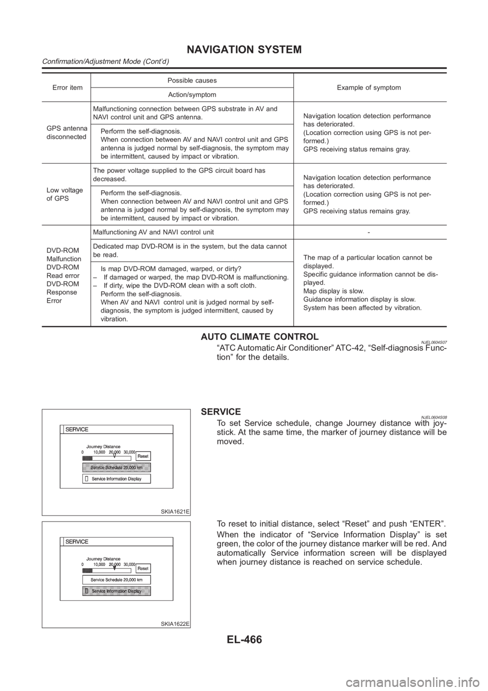
Error itemPossible causes
Example of symptom
Action/symptom
GPS antenna
disconnectedMalfunctioning connection between GPS substrate in AV and
NAVI control unit and GPS antenna.Navigation location detection performance
has deteriorated.
(Location correction using GPS is not per-
formed.)
GPS receiving status remains gray. Perform the self-diagnosis.
When connection between AV and NAVI control unit and GPS
antenna is judged normal by self-diagnosis, the symptom may
be intermittent, caused by impact or vibration.
Low voltage
of GPSThe power voltage supplied to the GPS circuit board has
decreased.Navigation location detection performance
has deteriorated.
(Location correction using GPS is not per-
formed.)
GPS receiving status remains gray. Perform the self-diagnosis.
When connection between AV and NAVI control unit and GPS
antenna is judged normal by self-diagnosis, the symptom may
be intermittent, caused by impact or vibration.
DVD-ROM
Malfunction
DVD-ROM
Read error
DVD-ROM
Response
ErrorMalfunctioning AV and NAVI control unit -
Dedicated map DVD-ROM is in the system, but the data cannot
be read.
The map of a particular location cannot be
displayed.
Specific guidance information cannot be dis-
played.
Map display is slow.
Guidance information display is slow.
System has been affected by vibration. Is map DVD-ROM damaged, warped, or dirty?
– If damaged or warped, the map DVD-ROM is malfunctioning.
– If dirty, wipe the DVD-ROM clean with a soft cloth.
Perform the self-diagnosis.
When AV and NAVI control unit is judged normal by self-
diagnosis, the symptom is judged intermittent, caused by
vibration.
AUTO CLIMATE CONTROLNJEL0604S07“ATC Automatic Air Conditioner” ATC-42, “Self-diagnosis Func-
tion” for the details.
SKIA1621E
SERVICENJEL0604S08To set Service schedule, change Journey distance with joy-
stick. At the same time, the marker of journey distance will be
moved.
SKIA1622E
To reset to initial distance, select “Reset” and push “ENTER”.
When the indicator of “Service Information Display” is set
green, the color of the journey distance marker will be red. And
automatically Service information screen will be displayed
when journey distance is reached on service schedule.
NAVIGATION SYSTEM
Confirmation/Adjustment Mode (Cont’d)
EL-466
Page 2803 of 3189
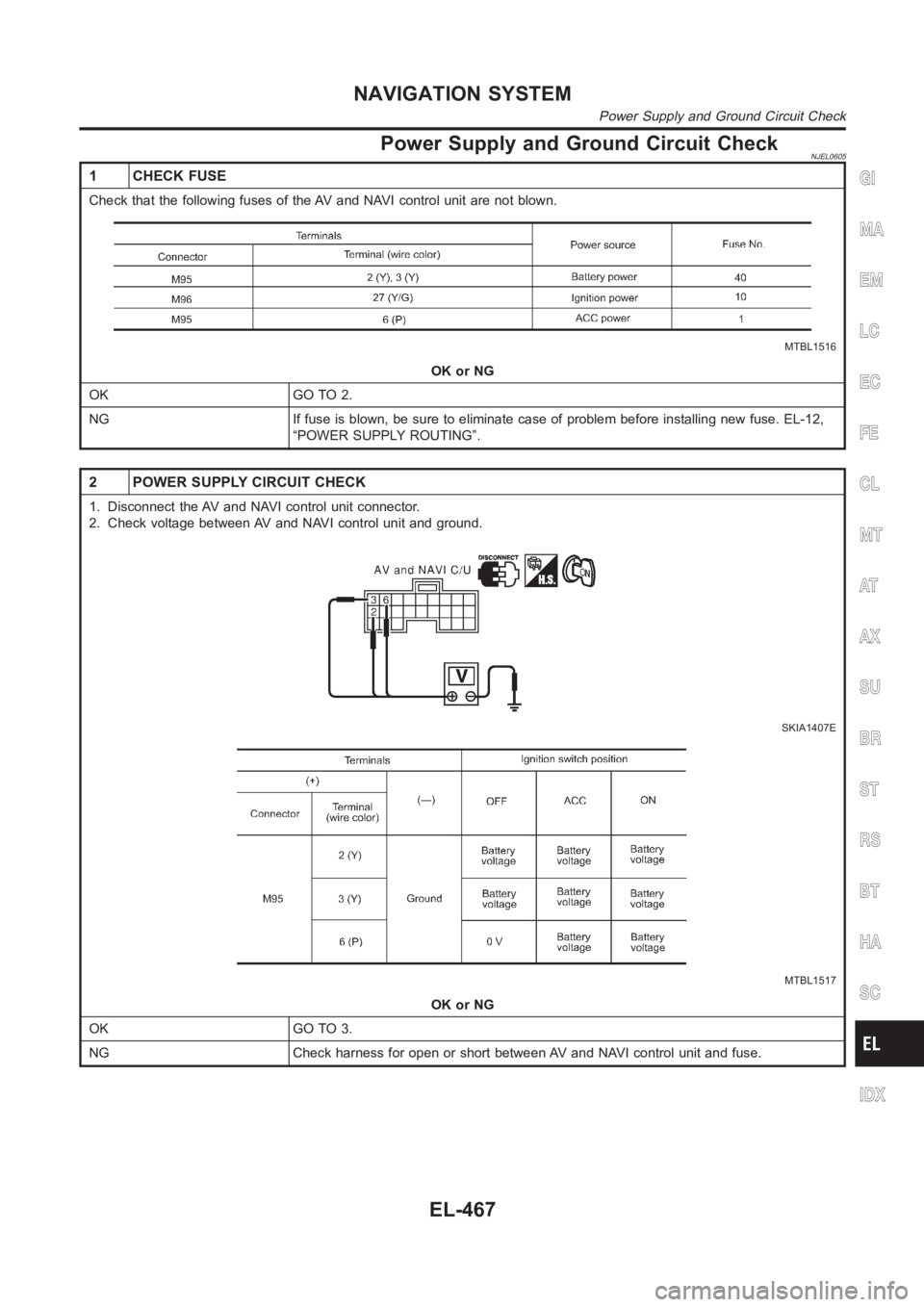
Power Supply and Ground Circuit CheckNJEL0605
1 CHECK FUSE
Check that the following fuses of the AV and NAVI control unit are not blown.
MTBL1516
OK or NG
OK GO TO 2.
NG If fuse is blown, be sure to eliminate case of problem before installing new fuse. EL-12,
“POWER SUPPLY ROUTING”.
2 POWER SUPPLY CIRCUIT CHECK
1. Disconnect the AV and NAVI control unit connector.
2. Check voltage between AV and NAVI control unit and ground.
SKIA1407E
MTBL1517
OK or NG
OK GO TO 3.
NG Check harness for open or short between AV and NAVI control unit and fuse.
GI
MA
EM
LC
EC
FE
CL
MT
AT
AX
SU
BR
ST
RS
BT
HA
SC
IDX
NAVIGATION SYSTEM
Power Supply and Ground Circuit Check
EL-467
Page 2804 of 3189
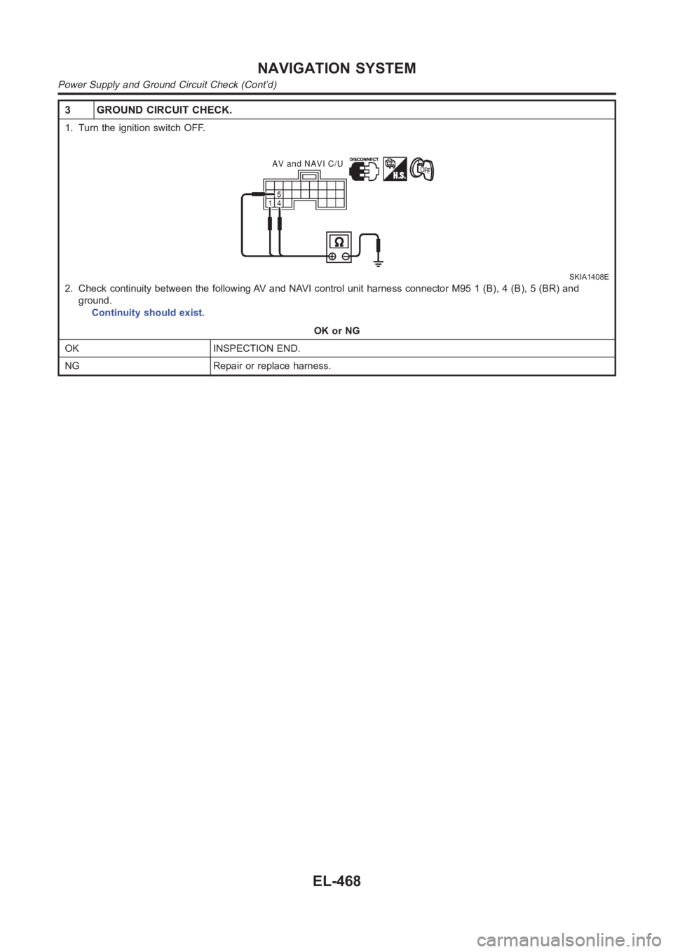
3 GROUND CIRCUIT CHECK.
1. Turn the ignition switch OFF.
SKIA1408E
2. Check continuity between the following AV and NAVI control unit harnessconnector M95 1 (B), 4 (B), 5 (BR) and
ground.
Continuity should exist.
OK or NG
OK INSPECTION END.
NG Repair or replace harness.
NAVIGATION SYSTEM
Power Supply and Ground Circuit Check (Cont’d)
EL-468
Page 2805 of 3189
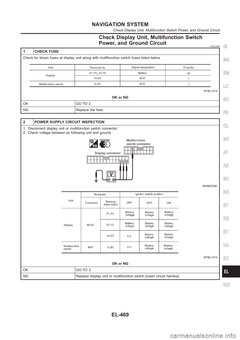
Check Display Unit, Multifunction Switch
Power, and Ground Circuit
=NJEL0606
1 CHECK FUSE
Check for blown fuses at display unit along with multifunction switch fuses listed below.
MTBL1518
OK or NG
OK GO TO 2.
NG Replace the fuse.
2 POWER SUPPLY CIRCUIT INSPECTION
1. Disconnect display unit or multifunction switch connector.
2. Check voltage between as following unit and ground.
MKIB0259E
MTBL1519
OK or NG
OK GO TO 3.
NG Replace display unit or multifunction switch power circuit harness.
GI
MA
EM
LC
EC
FE
CL
MT
AT
AX
SU
BR
ST
RS
BT
HA
SC
IDX
NAVIGATION SYSTEM
Check Display Unit, Multifunction Switch Power, and Ground Circuit
EL-469
Page 2806 of 3189
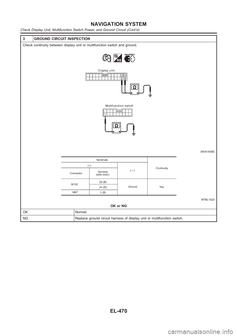
3 GROUND CIRCUIT INSPECTION
Check continuity between display unit or multifunction switch and ground.
SKIA1409E
MTBL1520
OK or NG
OK Normal.
NG Replace ground circuit harness of display unit or multifunction switch.
NAVIGATION SYSTEM
Check Display Unit, Multifunction Switch Power, and Ground Circuit (Cont’d)
EL-470
Page 2807 of 3189
Vehicle Speed Signal CheckNJEL0607
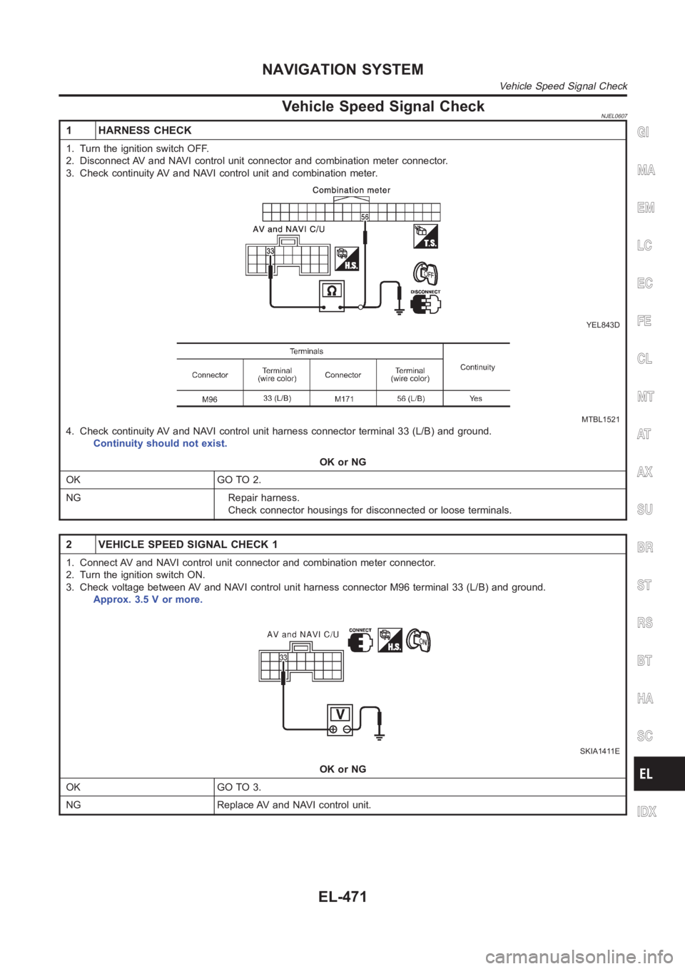
1 HARNESS CHECK
1. Turn the ignition switch OFF.
2. Disconnect AV and NAVI control unit connector and combination meter connector.
3. Check continuity AV and NAVI control unit and combination meter.
YEL843D
MTBL1521
4. Check continuity AV and NAVI control unit harness connector terminal 33(L/B) and ground.
Continuity should not exist.
OK or NG
OK GO TO 2.
NG Repair harness.
Check connector housings for disconnected or loose terminals.
2 VEHICLE SPEED SIGNAL CHECK 1
1. Connect AV and NAVI control unit connector and combination meter connector.
2. Turn the ignition switch ON.
3. Check voltage between AV and NAVI control unit harness connector M96 terminal 33 (L/B) and ground.
Approx. 3.5 V or more.
SKIA1411E
OK or NG
OK GO TO 3.
NG Replace AV and NAVI control unit.
GI
MA
EM
LC
EC
FE
CL
MT
AT
AX
SU
BR
ST
RS
BT
HA
SC
IDX
NAVIGATION SYSTEM
Vehicle Speed Signal Check
EL-471
Page 2808 of 3189
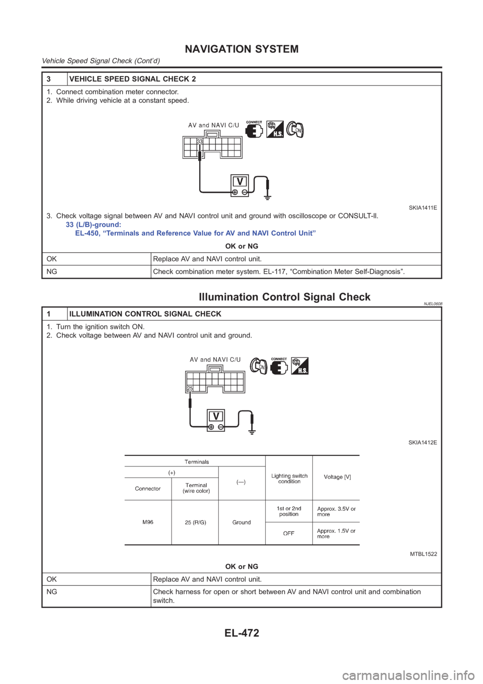
3 VEHICLE SPEED SIGNAL CHECK 2
1. Connect combination meter connector.
2. While driving vehicle at a constant speed.
SKIA1411E
3. Check voltage signal between AV and NAVI control unit and ground with oscilloscope or CONSULT-ll.
33 (L/B)-ground:
EL-450, “Terminals and Reference Value for AV and NAVI Control Unit”
OK or NG
OK Replace AV and NAVI control unit.
NG Check combination meter system. EL-117, “Combination Meter Self-Diagnosis”.
Illumination Control Signal CheckNJEL0608
1 ILLUMINATION CONTROL SIGNAL CHECK
1. Turn the ignition switch ON.
2. Check voltage between AV and NAVI control unit and ground.
SKIA1412E
MTBL1522
OK or NG
OK Replace AV and NAVI control unit.
NG Check harness for open or short between AV and NAVI control unit and combination
switch.
NAVIGATION SYSTEM
Vehicle Speed Signal Check (Cont’d)
EL-472
Page 2809 of 3189
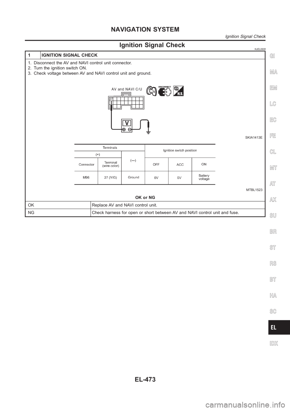
Ignition Signal CheckNJEL0609
1 IGNITION SIGNAL CHECK
1. Disconnect the AV and NAVI control unit connector.
2. Turn the ignition switch ON.
3. Check voltage between AV and NAVI control unit and ground.
SKIA1413E
MTBL1523
OK or NG
OK Replace AV and NAVI control unit.
NG Check harness for open or short between AV and NAVI control unit and fuse.
GI
MA
EM
LC
EC
FE
CL
MT
AT
AX
SU
BR
ST
RS
BT
HA
SC
IDX
NAVIGATION SYSTEM
Ignition Signal Check
EL-473
Page 2810 of 3189
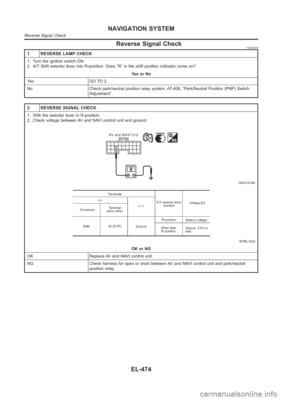
Reverse Signal Check=NJEL0610
1 REVERSE LAMP CHECK
1. Turn the ignition switch ON.
2. A/T Shift selector lever into R-position. Does “R” in the shift positionindicator come on?
YesorNo
Ye s G O T O 2 .
No Check park/neutral position relay system. AT-408, “Park/Neutral Position (PNP) Switch
Adjustment”.
2 REVERSE SIGNAL CHECK
1. With the selector lever in R-position.
2. Check voltage between AV and NAVI control unit and ground.
SKIA1414E
MTBL1524
OK or NG
OK Replace AV and NAVI control unit.
NG Check harness for open or short between AV and NAVI control unit and park/neutral
position relay.
NAVIGATION SYSTEM
Reverse Signal Check
EL-474