NISSAN ALMERA N16 2003 Electronic Repair Manual
ALMERA N16 2003
NISSAN
NISSAN
https://www.carmanualsonline.info/img/5/57350/w960_57350-0.png
NISSAN ALMERA N16 2003 Electronic Repair Manual
Trending: lighting switch, manual radio set, Starter, automatic transmission, combination meter, hl lamp, Power condition
Page 2781 of 3189
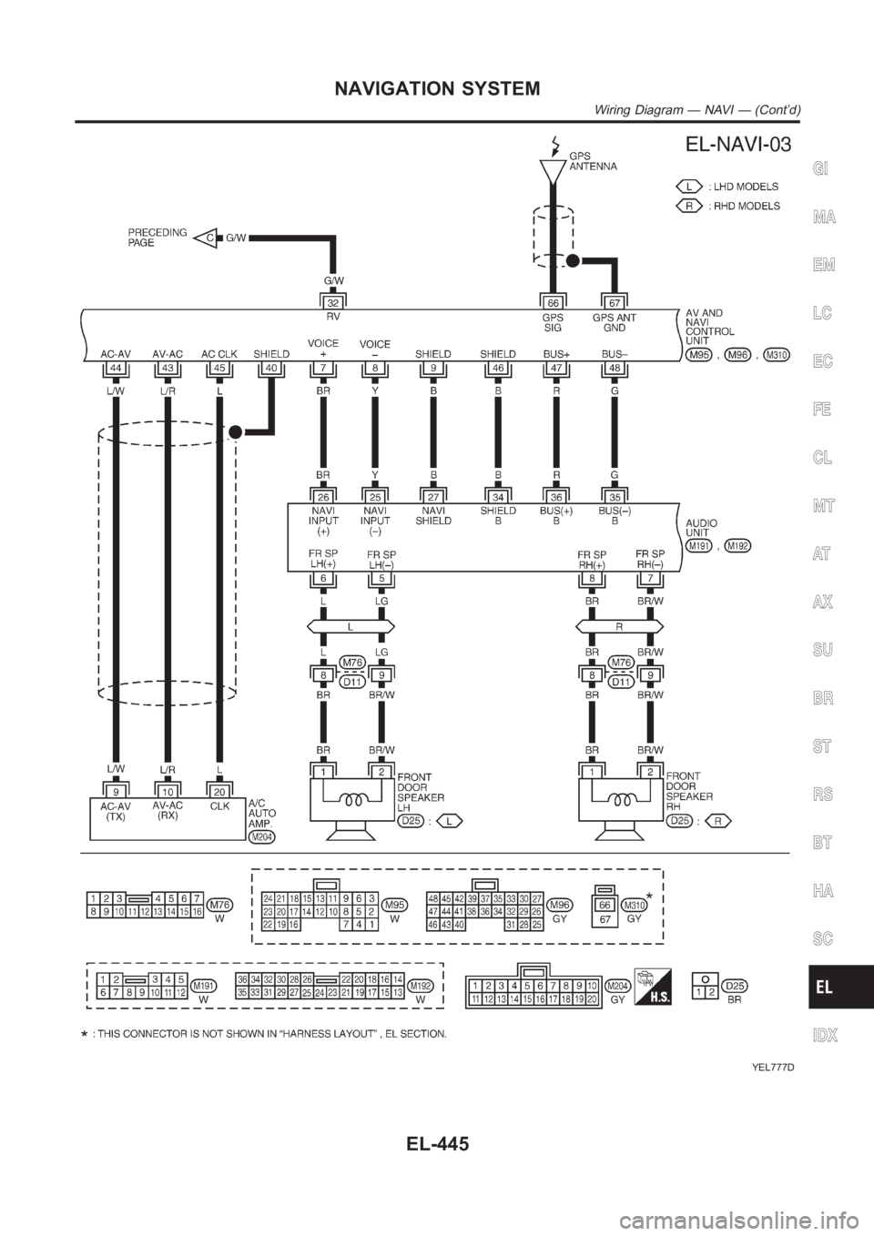
YEL777D
GI
MA
EM
LC
EC
FE
CL
MT
AT
AX
SU
BR
ST
RS
BT
HA
SC
IDX
NAVIGATION SYSTEM
Wiring Diagram — NAVI — (Cont’d)
EL-445
Page 2782 of 3189
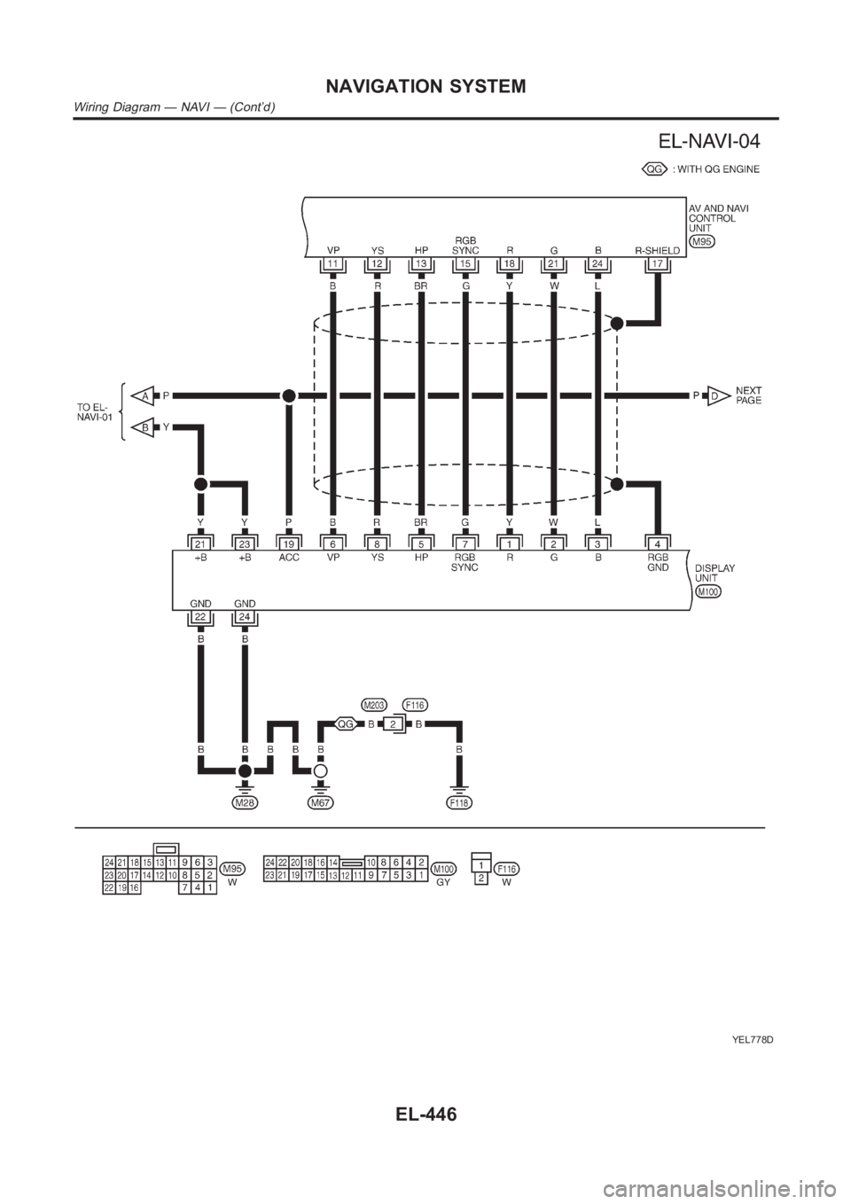
YEL778D
NAVIGATION SYSTEM
Wiring Diagram — NAVI — (Cont’d)
EL-446
Page 2783 of 3189
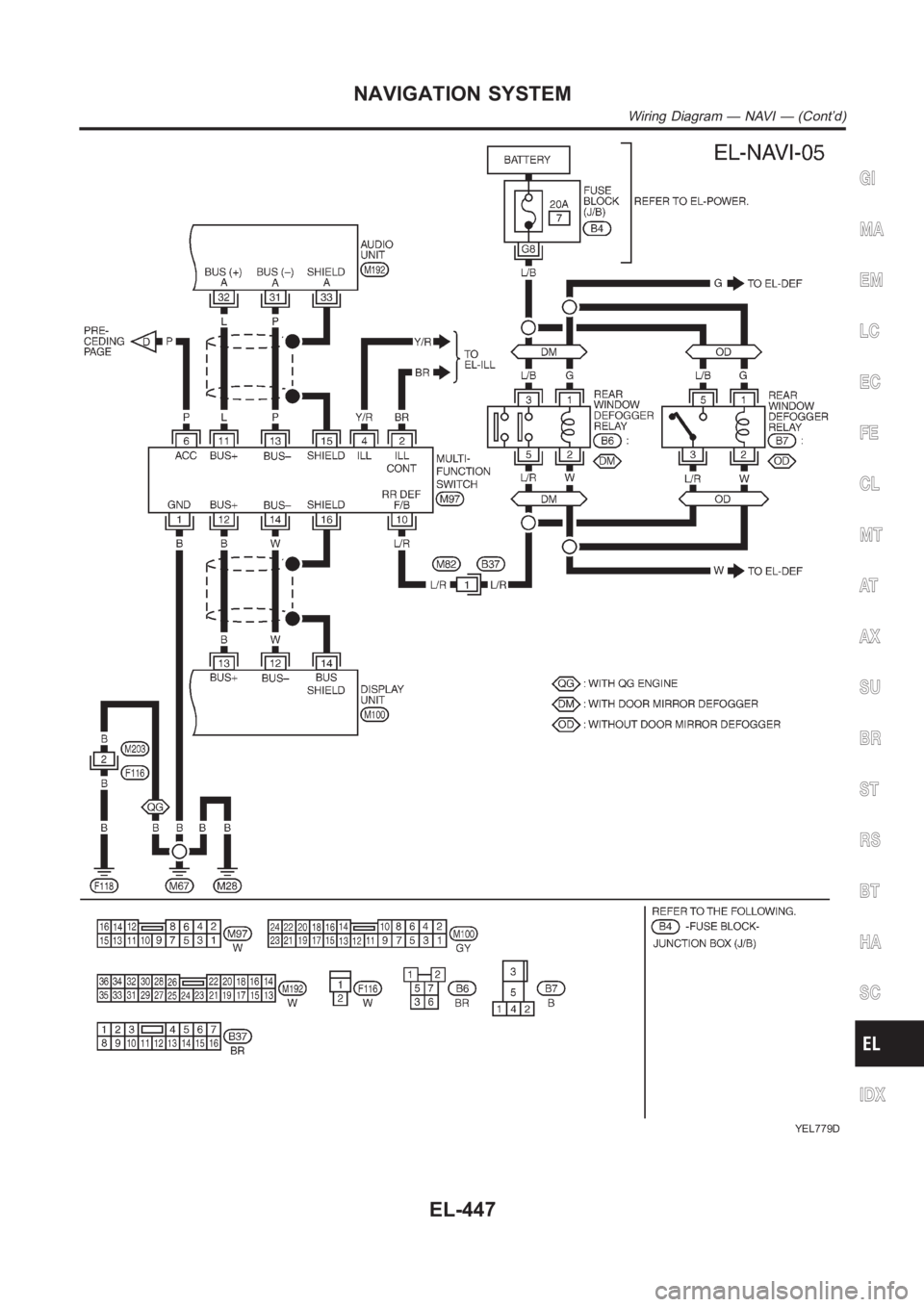
YEL779D
GI
MA
EM
LC
EC
FE
CL
MT
AT
AX
SU
BR
ST
RS
BT
HA
SC
IDX
NAVIGATION SYSTEM
Wiring Diagram — NAVI — (Cont’d)
EL-447
Page 2784 of 3189
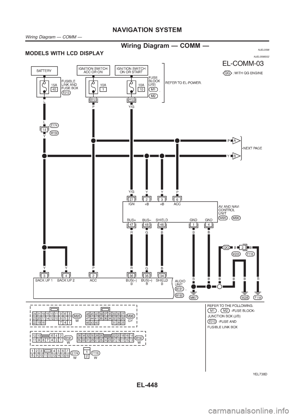
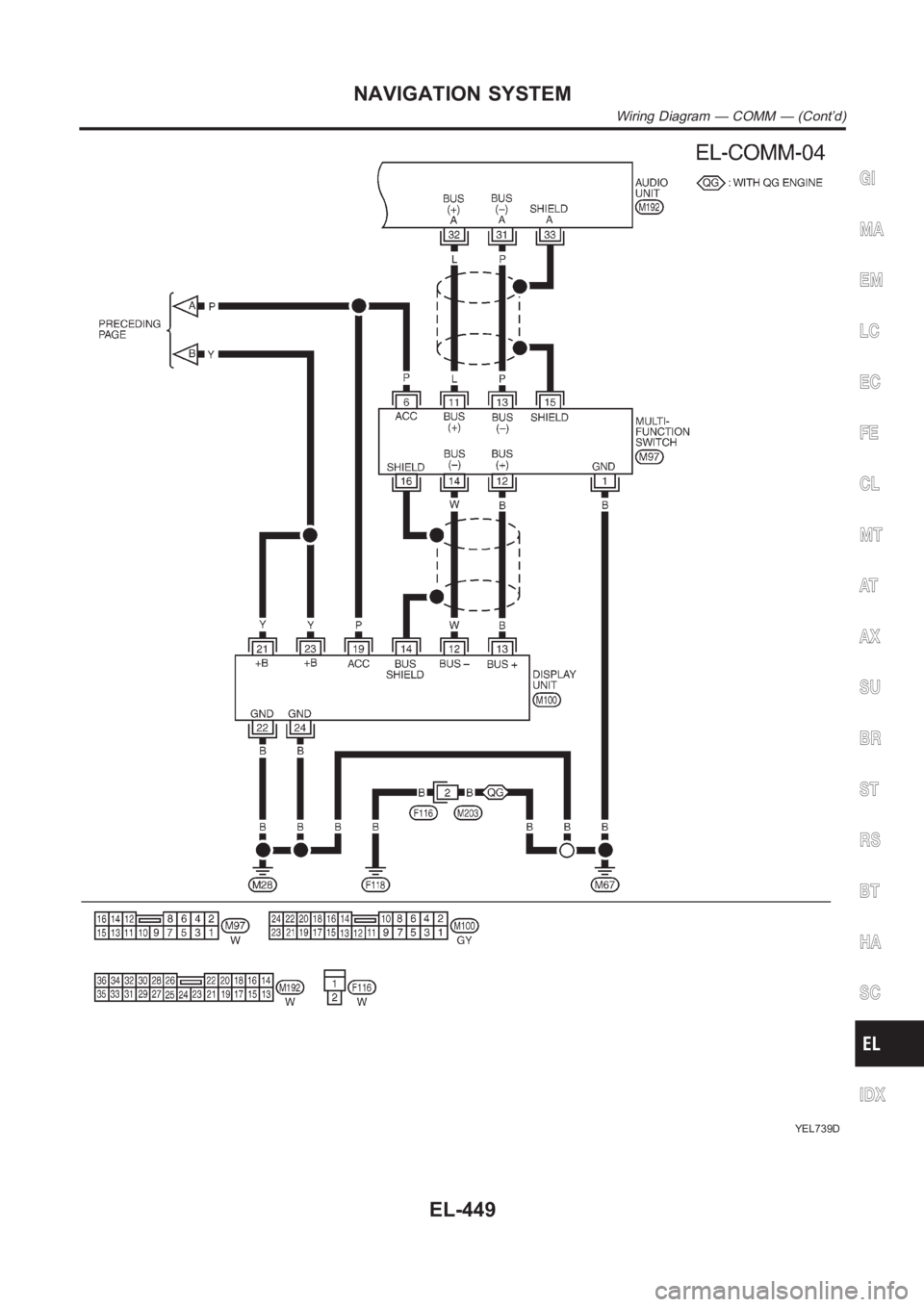
Wiring Diagram — COMM —NJEL0598MODELS WITH LCD DISPLAYNJEL0598S02
YEL738D
NAVIGATION SYSTEM
Wiring Diagram — COMM —
EL-448
Page 2785 of 3189
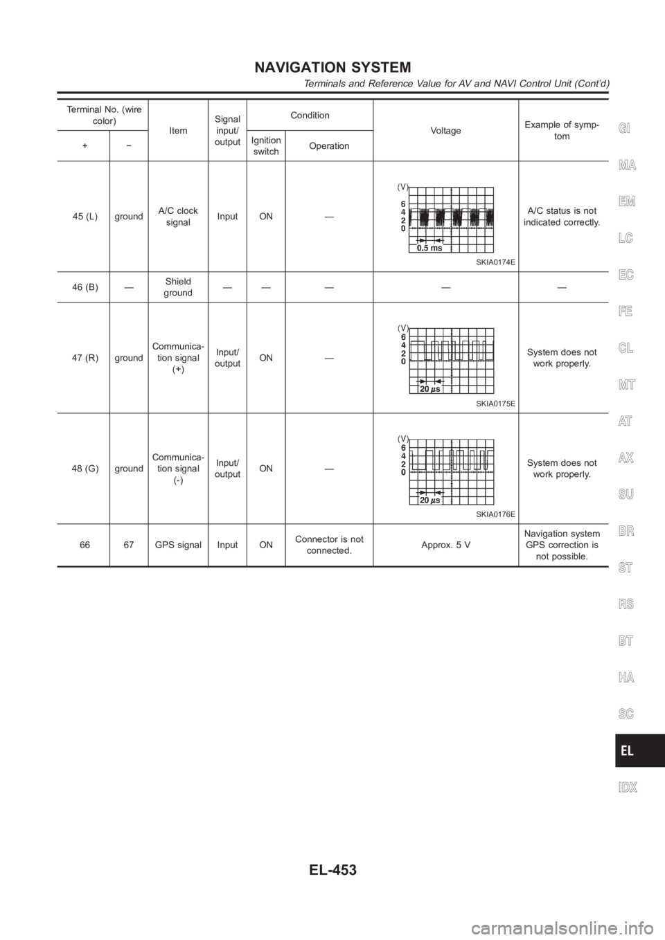
YEL739D
GI
MA
EM
LC
EC
FE
CL
MT
AT
AX
SU
BR
ST
RS
BT
HA
SC
IDX
NAVIGATION SYSTEM
Wiring Diagram — COMM — (Cont’d)
EL-449
Page 2786 of 3189
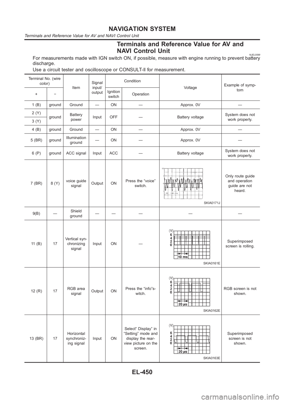
Terminals and Reference Value for AV and
NAVI Control Unit
NJEL0599For measurements made with IGN switch ON, if possible, measure with enginerunning to prevent battery
discharge.
Use a circuit tester and oscilloscope or CONSULT-ll for measurement.
Terminal No. (wire
color)
ItemSignal
input/
outputCondition
VoltageExample of symp-
tom
+−Ignition
switchOperation
1 (B) ground Ground — ON — Approx. 0V —
2 (Y)
groundBattery
powerInput OFF — Battery voltageSystem does not
work properly.
3 (Y)
4 (B) ground Ground — ON — Approx. 0V —
5 (BR) groundIllumination
ground— ON — Approx. 0V —
6 (P) ground ACC signal Input ACC — Battery voltageSystem does not
work properly.
7 (BR) 8 (Y)voice guide
signalOutput ONPress the “voice”
switch.
SKIA0171J
Only route guide
and operation
guide are not
heard.
9(B) —Shield
ground—— — — —
11 (B) 17Vertical syn-
chronizing
signalInput ON —
SKIA0161E
Superimposed
screen is rolling.
12 (R) 17RGB area
signalOutput ONPress the “info”s-
witch.
SKIA0162E
RGB screen is not
shown.
13 (BR) 17Horizontal
synchroniz-
ing signalInput ONSelect“ Display” in
“Setting” mode and
display the rear-
view picture on the
screen.
SKIA0163E
Superimposed
screen is not
shown.
NAVIGATION SYSTEM
Terminals and Reference Value for AV and NAVI Control Unit
EL-450
Page 2787 of 3189
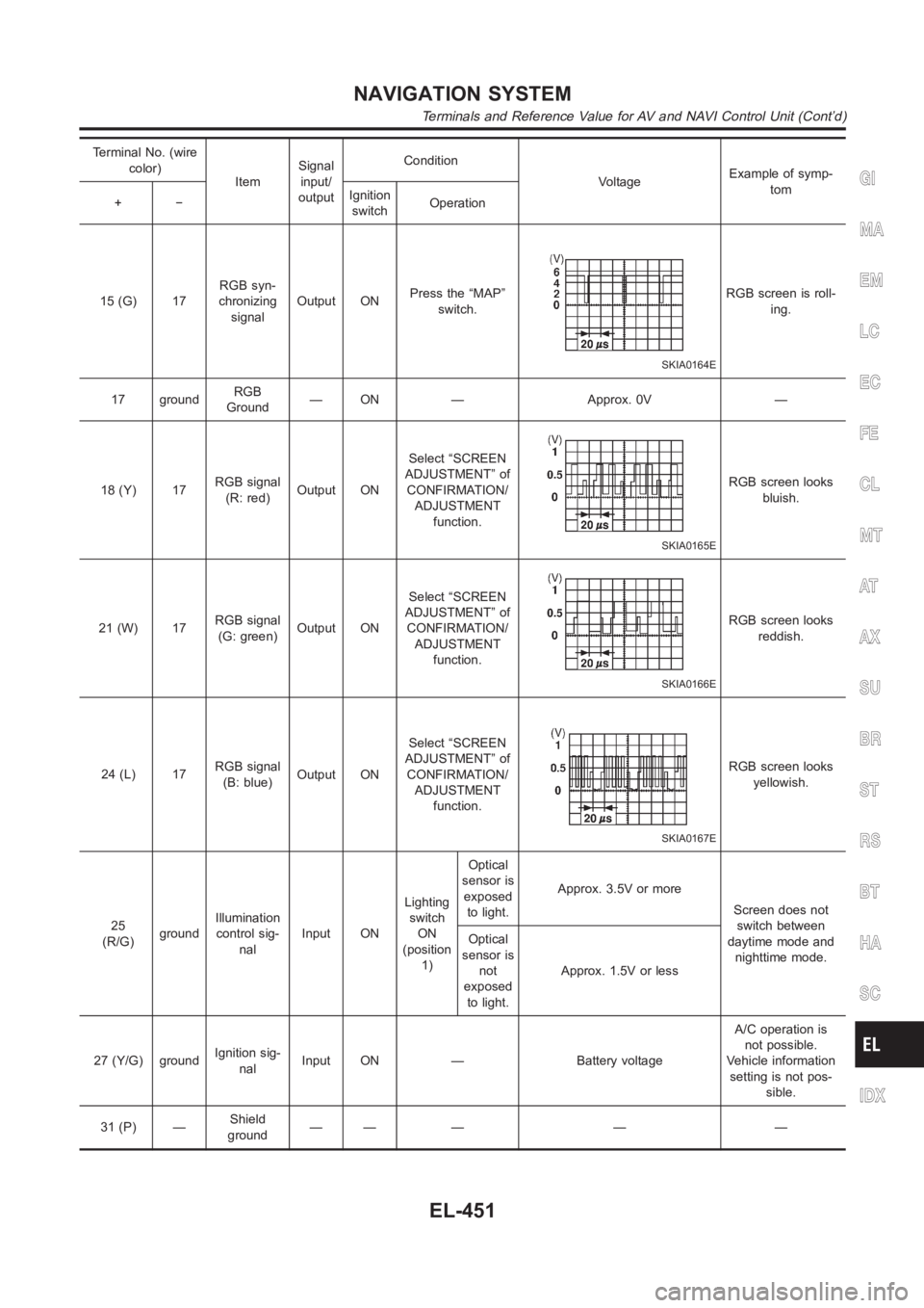
Terminal No. (wire
color)
ItemSignal
input/
outputCondition
VoltageExample of symp-
tom
+−Ignition
switchOperation
15 (G) 17RGB syn-
chronizing
signalOutput ONPress the “MAP”
switch.
SKIA0164E
RGB screen is roll-
ing.
17 groundRGB
Ground— ON — Approx. 0V —
18 (Y) 17RGB signal
(R: red)Output ONSelect “SCREEN
ADJUSTMENT” of
CONFIRMATION/
ADJUSTMENT
function.
SKIA0165E
RGB screen looks
bluish.
21 (W) 17RGB signal
(G: green)Output ONSelect “SCREEN
ADJUSTMENT” of
CONFIRMATION/
ADJUSTMENT
function.
SKIA0166E
RGB screen looks
reddish.
24 (L) 17RGB signal
(B: blue)Output ONSelect “SCREEN
ADJUSTMENT” of
CONFIRMATION/
ADJUSTMENT
function.
SKIA0167E
RGB screen looks
yellowish.
25
(R/G)groundIllumination
control sig-
nalInput ONLighting
switch
ON
(position
1)Optical
sensor is
exposed
to light.Approx. 3.5V or more
Screen does not
switch between
daytime mode and
nighttime mode. Optical
sensor is
not
exposed
to light.Approx. 1.5V or less
27 (Y/G) groundIgnition sig-
nalInput ON — Battery voltageA/C operation is
not possible.
Vehicle information
setting is not pos-
sible.
31 (P) —Shield
ground—— — — —
GI
MA
EM
LC
EC
FE
CL
MT
AT
AX
SU
BR
ST
RS
BT
HA
SC
IDX
NAVIGATION SYSTEM
Terminals and Reference Value for AV and NAVI Control Unit (Cont’d)
EL-451
Page 2788 of 3189
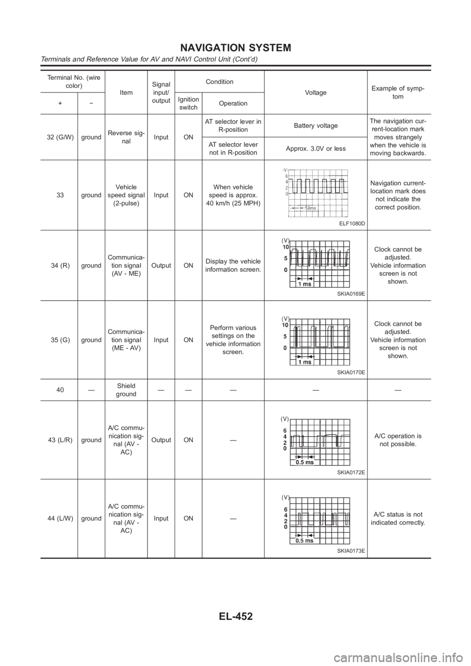
Terminal No. (wire
color)
ItemSignal
input/
outputCondition
VoltageExample of symp-
tom
+−Ignition
switchOperation
32 (G/W) groundReverse sig-
nalInput ONAT selector lever in
R-positionBattery voltageThe navigation cur-
rent-location mark
moves strangely
when the vehicle is
moving backwards. AT selector lever
not in R-positionApprox. 3.0V or less
33 groundVehicle
speed signal
(2-pulse)Input ONWhen vehicle
speed is approx.
40 km/h (25 MPH)
ELF1080D
Navigation current-
location mark does
not indicate the
correct position.
34 (R) groundCommunica-
tion signal
(AV - ME)Output ONDisplay the vehicle
information screen.
SKIA0169E
Clock cannot be
adjusted.
Vehicle information
screen is not
shown.
35 (G) groundCommunica-
tion signal
(ME - AV)Input ONPerform various
settings on the
vehicle information
screen.
SKIA0170E
Clock cannot be
adjusted.
Vehicle information
screen is not
shown.
40 —Shield
ground—— — — —
43 (L/R) groundA/C commu-
nication sig-
nal (AV -
AC)Output ON —
SKIA0172E
A/C operation is
not possible.
44 (L/W) groundA/C commu-
nication sig-
nal (AV -
AC)Input ON —
SKIA0173E
A/C status is not
indicated correctly.
NAVIGATION SYSTEM
Terminals and Reference Value for AV and NAVI Control Unit (Cont’d)
EL-452
Page 2789 of 3189
Terminal No. (wire
color)
ItemSignal
input/
outputCondition
VoltageExample of symp-
tom
+−Ignition
switchOperation
45 (L) groundA/C clock
signalInput ON —
SKIA0174E
A/C status is not
indicated correctly.
46 (B) —Shield
ground—— — — —
47 (R) groundCommunica-
tion signal
(+)Input/
outputON —
SKIA0175E
System does not
work properly.
48 (G) groundCommunica-
tion signal
(-)Input/
outputON —
SKIA0176E
System does not
work properly.
66 67 GPS signal Input ONConnector is not
connected.Approx. 5 VNavigation system
GPS correction is
not possible.
GI
MA
EM
LC
EC
FE
CL
MT
AT
AX
SU
BR
ST
RS
BT
HA
SC
IDX
NAVIGATION SYSTEM
Terminals and Reference Value for AV and NAVI Control Unit (Cont’d)
EL-453
Page 2790 of 3189
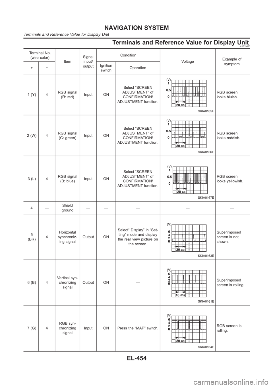
Terminals and Reference Value for Display UnitNJEL0600
Terminal No.
(wire color)
ItemSignal
input/
outputCondition
VoltageExample of
symptom
+−Ignition
switchOperation
1 (Y) 4RGB signal
(R: red)Input ONSelect “SCREEN
ADJUSTMENT” of
CONFIRMATION/
ADJUSTMENT function.
SKIA0165E
RGB screen
looks bluish.
2(W) 4RGB signal
(G: green)Input ONSelect “SCREEN
ADJUSTMENT” of
CONFIRMATION/
ADJUSTMENT function.
SKIA0166E
RGB screen
looks reddish.
3(L) 4RGB signal
(B: blue)Input ONSelect “SCREEN
ADJUSTMENT” of
CONFIRMATION/
ADJUSTMENT function.
SKIA0167E
RGB screen
looks yellowish.
4—Shield
ground—— — — —
5
(BR)4Horizontal
synchroniz-
ing signalOutput ONSelect“ Display” in “Set-
ting” mode and display
the rear view picture on
the screen.
SKIA0163E
Superimposed
screen is not
shown.
6 (B) 4Vertical syn-
chronizing
signalOutput ON —
SKIA0161E
Superimposed
screen is rolling.
7(G) 4RGB syn-
chronizing
signalInput ON Press the “MAP” switch.
SKIA0164E
RGB screen is
rolling.
NAVIGATION SYSTEM
Terminals and Reference Value for Display Unit
EL-454
Trending: electric diagram, Pump, ABS, coolant, Front %26 rear axle, Ckp, pressure
