NISSAN ALMERA N16 2003 Electronic Repair Manual
Manufacturer: NISSAN, Model Year: 2003, Model line: ALMERA N16, Model: NISSAN ALMERA N16 2003Pages: 3189, PDF Size: 54.76 MB
Page 2841 of 3189
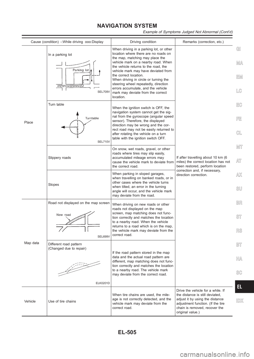
Cause (condition) -:While driving ooo:Display Driving condition Remarks (correction, etc.)
PlaceIn a parking lot
SEL709V
When driving in a parking lot, or other
location where there are no roads on
the map, matching may place the
vehicle mark on a nearby road. When
the vehicle returns to the road, the
vehicle mark may have deviated from
the correct location.
When driving in circle or turning the
steering wheel repeatedly, direction
errors accumulate, and the vehicle
mark may deviate from the correct
location.
If after travelling about 10 km (6
miles) the correct location has not
been restored, perform location
correction and, if necessary,
direction correction. Turn table
SEL710V
When the ignition switch is OFF, the
navigation system cannot get the sig-
nal from the gyroscope (angular speed
sensor). Therefore, the displayed
direction may be wrong and the cor-
rect road may not be easily returned to
after rotating the vehicle on a turn
table with the ignition switch OFF.
Slippery roadsOn snow, wet roads, gravel, or other
roads where tires may slip easily,
accumulated mileage errors may
cause the vehicle mark to deviate from
the correct road.
SlopesWhen parking in sloped garages,
when travelling on banked roads, or in
other cases where the vehicle turns
when tilted, an error in the turning
angle will occur, and the vehicle mark
may deviate from the road.
Map dataRoad not displayed on the map screen
SEL699V
When driving on new roads or other
roads not displayed on the map
screen, map matching does not func-
tion correctly and matches the location
to a nearby road. When the vehicle
returns to a road which is on the map,
the vehicle mark may deviate from the
correct road.
Different road pattern
(Changed due to repair)
ELK0201D
If the road pattern stored in the map
data and the actual road pattern are
different, map matching does not func-
tion correctly and matches the location
to a nearby road. The vehicle mark
may deviate from the correct road.
Vehicle Use of tire chainsWhen tire chains are used, the mile-
age is not correctly detected, and the
vehicle mark may deviate from the
correct road.Drive the vehicle for a while. If
the distance is still deviated,
adjust it by using the distance
adjustment function. (If the tire
chain is removed, recover the
original value.)
GI
MA
EM
LC
EC
FE
CL
MT
AT
AX
SU
BR
ST
RS
BT
HA
SC
IDX
NAVIGATION SYSTEM
Example of Symptoms Judged Not Abnormal (Cont’d)
EL-505
Page 2842 of 3189
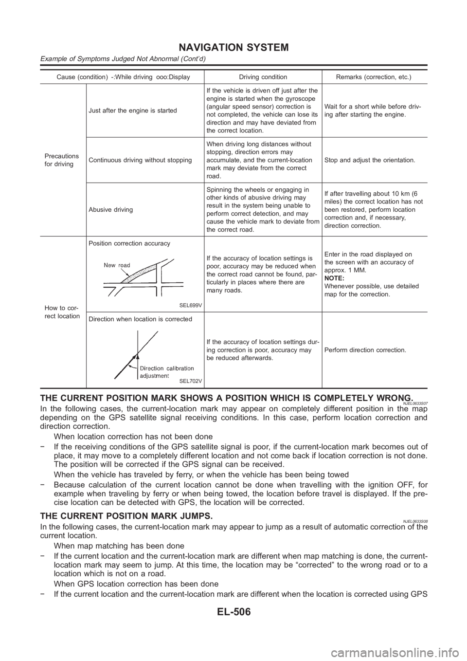
Cause (condition) -:While driving ooo:Display Driving condition Remarks (correction, etc.)
Precautions
for drivingJust after the engine is startedIf the vehicle is driven off just after the
engine is started when the gyroscope
(angular speed sensor) correction is
not completed, the vehicle can lose its
direction and may have deviated from
the correct location.Wait for a short while before driv-
ing after starting the engine.
Continuous driving without stoppingWhen driving long distances without
stopping, direction errors may
accumulate, and the current-location
mark may deviate from the correct
road.Stop and adjust the orientation.
Abusive drivingSpinning the wheels or engaging in
other kinds of abusive driving may
result in the system being unable to
perform correct detection, and may
cause the vehicle mark to deviate from
the correct road.If after travelling about 10 km (6
miles) the correct location has not
been restored, perform location
correction and, if necessary,
direction correction.
How to cor-
rect locationPosition correction accuracy
SEL699V
If the accuracy of location settings is
poor, accuracy may be reduced when
the correct road cannot be found, par-
ticularly in places where there are
many roads.Enter in the road displayed on
the screen with an accuracy of
approx. 1 MM.
NOTE:
Whenever possible, use detailed
map for the correction.
Direction when location is corrected
SEL702V
If the accuracy of location settings dur-
ing correction is poor, accuracy may
be reduced afterwards.Perform direction correction.
THE CURRENT POSITION MARK SHOWS A POSITION WHICH IS COMPLETELY WRONG.NJEL0633S07In the following cases, the current-location mark may appear on completely different position in the map
depending on the GPS satellite signal receiving conditions. In this case,perform location correction and
direction correction.
When location correction has not been done
− If the receiving conditions of the GPS satellite signal is poor, if the current-location mark becomes out of
place, it may move to a completely different location and not come back if location correction is not done.
The position will be corrected if the GPS signal can be received.
When the vehicle has traveled by ferry, or when the vehicle has been being towed
− Because calculation of the current location cannot be done when travelling with the ignition OFF, for
example when traveling by ferry or when being towed, the location before travel is displayed. If the pre-
cise location can be detected with GPS, the location will be corrected.
THE CURRENT POSITION MARK JUMPS.NJEL0633S08In the following cases, the current-location mark may appear to jump as a result of automatic correction of the
current location.
When map matching has been done
− If the current location and the current-location mark are different whenmap matching is done, the current-
location mark may seem to jump. At this time, the location may be “corrected” to the wrong road or to a
location which is not on a road.
When GPS location correction has been done
− If the current location and the current-location mark are different whenthe location is corrected using GPS
NAVIGATION SYSTEM
Example of Symptoms Judged Not Abnormal (Cont’d)
EL-506
Page 2843 of 3189
measurements, the current-location mark may seem to jump. At this time, the location may be “corrected”
to a location which is not on a road.
THE CURRENT LOCATION MARK IS IN A RIVER OR THE SEA.NJEL0633S09The navigation system moves the current location mark with no distinctionbetween land and rivers or sea. If
the location mark is somehow out of place, it may appear that the vehicle is driving in a river or the sea.
WHEN DRIVING ON THE SAME ROAD, SOMETIMES THE CURRENT-LOCATION MARK IS IN
THE RIGHT PLACE AND SOMETIMES IT IS THE WRONG PLACE.
NJEL0633S10The conditions of the GPS antenna (GPS data) and gyroscope (angular speed sensor) change gradually.
Depending on the road traveled and the operation of the steering wheel, thelocation detection results will be
different. Therefore, even on a road on which the location has never been wrong, conditions may cause the
vehicle mark to deviate.
LOCATION CORRECTION BY MAP MATCHING IS SLOW.NJEL0633S11The map matching function needs to refer to the data of the surrounding area. It is necessary to drive some
distance for the function to work.
Because map matching operates on this principle, when there are many roadsrunning in similar direc-
tions in the surrounding area, no matching determination may be made. The location may not be corrected
until some special feature is found.
ALTHOUGH THE GPS RECEIVING DISPLAY IS GREEN, THE VEHICLE MARK DOES NOT
RETURN TO THE CORRECT LOCATION.
NJEL0633S12The GPS accuracy has an error of about 10 m (30 ft). In some cases the current-location mark may not
be on the correct street, even when GPS location-correction is done.
The navigation system compares the results of GPS location detection withthe results from map-match-
ing location detection. The one which is determined to have higher accuracyisused.
GPS location correction may not be performed when the vehicle is stopped.
THE NAME OF THE CURRENT PLACE IS NOT DISPLAYED.NJEL0633S13The current place name may not be displayed if there are no place names displayed on the map screen.
CONTENTS OF THE DISPLAY DIFFER FOR THE BIRDVIEW AND THE (FLAT) MAP
SCREEN.
NJEL0633S14Difference of the BIRDVIEW Screen From the Flat Map Screen Are as Follows.NJEL0633S1401The current place name displays names which are primarily in the directionof vehicle travel.
The amount of time before the vehicle travel or turn angle is updated on the screen is longer than for the
(flat) map display.
The conditions for display of place names, roads, and other data are different for nearby areas and for
more distant areas.
Some thinning of the character data is done to prevent the display becomingto complex. In some cases
and in some locations, the display contents may differ.
The same place name, street name, etc. may be displayed multiple times.
GI
MA
EM
LC
EC
FE
CL
MT
AT
AX
SU
BR
ST
RS
BT
HA
SC
IDX
NAVIGATION SYSTEM
Example of Symptoms Judged Not Abnormal (Cont’d)
EL-507
Page 2844 of 3189
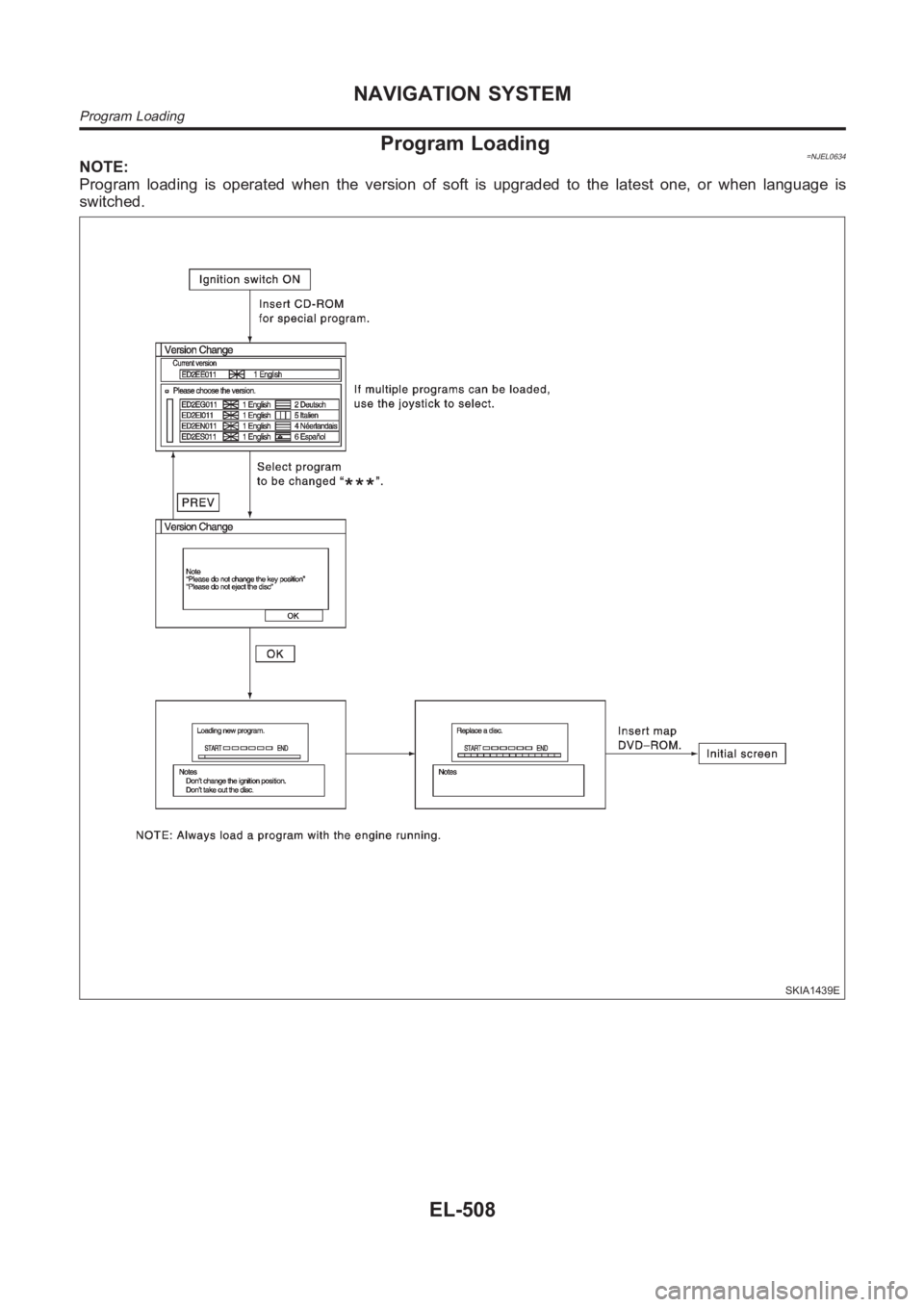
Program Loading=NJEL0634NOTE:
Program loading is operated when the version of soft is upgraded to the latest one, or when language is
switched.
SKIA1439E
NAVIGATION SYSTEM
Program Loading
EL-508
Page 2845 of 3189
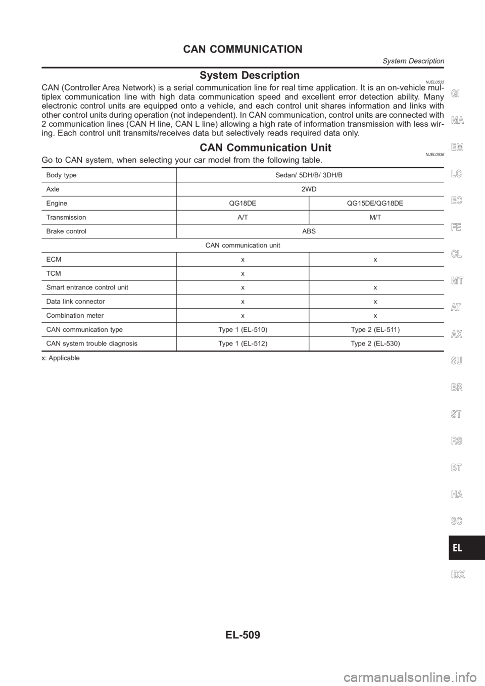
System DescriptionNJEL0535CAN (Controller Area Network) is a serial communication line for real timeapplication. It is an on-vehicle mul-
tiplex communication line with high data communication speed and excellent error detection ability. Many
electronic control units are equipped onto a vehicle, and each control unit shares information and links with
other control units during operation (not independent). In CAN communication, control units are connected with
2 communication lines (CAN H line, CAN L line) allowing a high rate of information transmission with less wir-
ing. Each control unit transmits/receives data but selectively reads requireddataonly.
CAN Communication UnitNJEL0536Go to CAN system, when selecting your car model from the following table.
Body type Sedan/ 5DH/B/ 3DH/B
Axle2WD
Engine QG18DE QG15DE/QG18DE
Transmission A/T M/T
Brake controlABS
CAN communication unit
ECM x x
TCM x
Smart entrance control unit x x
Data link connector x x
Combination meter x x
CAN communication type Type 1 (EL-510) Type 2 (EL-511)
CAN system trouble diagnosis Type 1 (EL-512) Type 2 (EL-530)
x: Applicable
GI
MA
EM
LC
EC
FE
CL
MT
AT
AX
SU
BR
ST
RS
BT
HA
SC
IDX
CAN COMMUNICATION
System Description
EL-509
Page 2846 of 3189
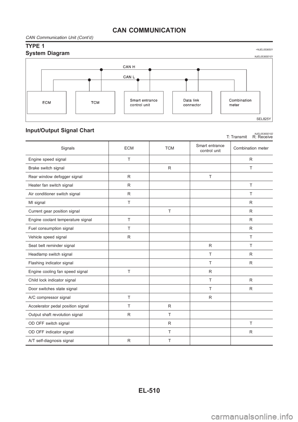
TYPE 1=NJEL0536S01System DiagramNJEL0536S0101
SEL825Y
Input/Output Signal ChartNJEL0536S0102T: Transmit R: Receive
Signals ECM TCMSmart entrance
control unitCombination meter
Engine speed signal T R
Brake switch signal R T
Rear window defogger signal R T
Heater fan switch signal R T
Air conditioner switch signal R T
MI signal T R
Current gear position signal T R
Engine coolant temperature signal T R
Fuel consumption signal T R
Vehicle speed signal R T
Seat belt reminder signalRT
Headlamp switch signalTR
Flashing indicator signalTR
Engine cooling fan speed signal T R
Child lock indicator signalTR
Door switches state signal T R
A/C compressor signal T R
Accelerator pedal position signal T R
Output shaft revolution signal R T
OD OFF switch signal R T
OD OFF indicator signal T R
A/T self-diagnosis signal R T
CAN COMMUNICATION
CAN Communication Unit (Cont’d)
EL-510
Page 2847 of 3189
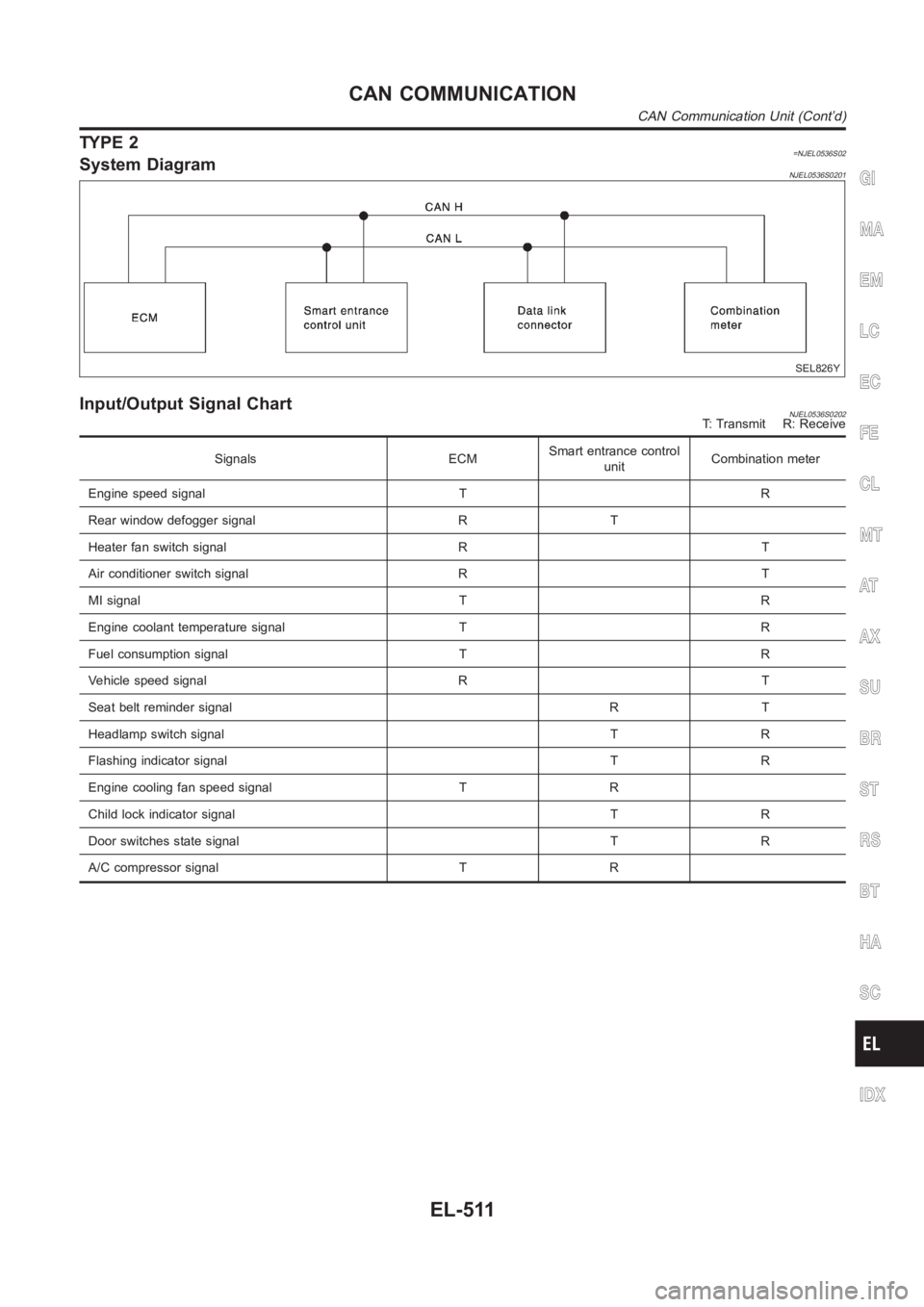
TYPE 2=NJEL0536S02System DiagramNJEL0536S0201
SEL826Y
Input/Output Signal ChartNJEL0536S0202T: Transmit R: Receive
Signals ECMSmart entrance control
unitCombination meter
Engine speed signal T R
Rear window defogger signal R T
Heater fan switch signal R T
Air conditioner switch signal R T
MI signal T R
Engine coolant temperature signal T R
Fuel consumption signal T R
Vehicle speed signal R T
Seat belt reminder signal R T
Headlamp switch signal T R
Flashing indicator signal T R
Engine cooling fan speed signal T R
Child lock indicator signal T R
Door switches state signal T R
A/C compressor signal T R
GI
MA
EM
LC
EC
FE
CL
MT
AT
AX
SU
BR
ST
RS
BT
HA
SC
IDX
CAN COMMUNICATION
CAN Communication Unit (Cont’d)
EL-511
Page 2848 of 3189
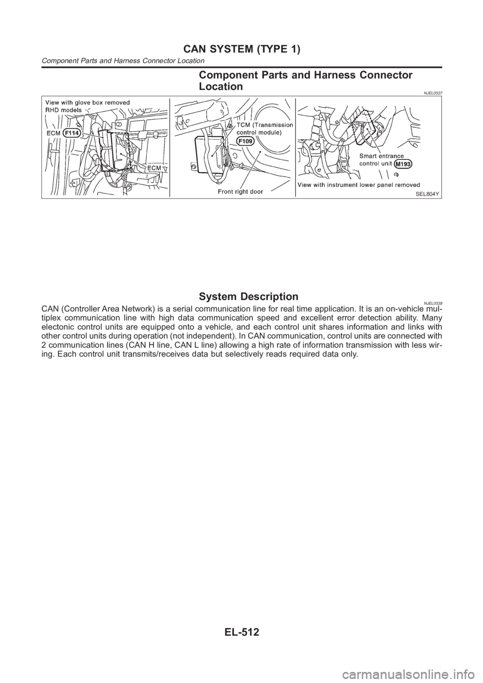
Component Parts and Harness Connector
Location
NJEL0537
SEL804Y
System DescriptionNJEL0538CAN (Controller Area Network) is a serial communication line for real timeapplication. It is an on-vehicle mul-
tiplex communication line with high data communication speed and excellent error detection ability. Many
electonic control units are equipped onto a vehicle, and each control unitshares information and links with
other control units during operation (not independent). In CAN communication, control units are connected with
2 communication lines (CAN H line, CAN L line) allowing a high rate of information transmission with less wir-
ing. Each control unit transmits/receives data but selectively reads requireddataonly.
CAN SYSTEM (TYPE 1)
Component Parts and Harness Connector Location
EL-512
Page 2849 of 3189
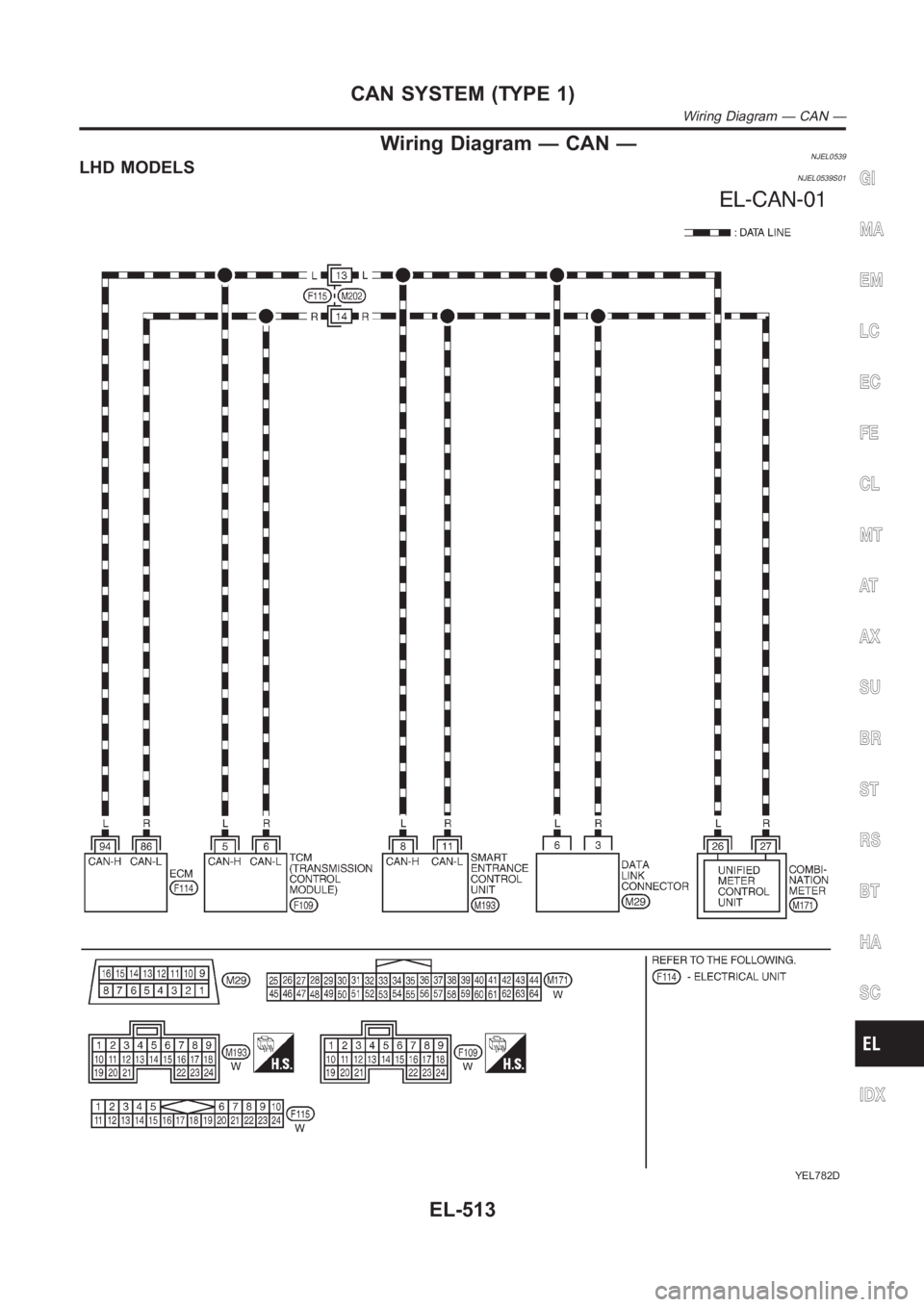
Wiring Diagram — CAN —NJEL0539LHD MODELSNJEL0539S01
YEL782D
GI
MA
EM
LC
EC
FE
CL
MT
AT
AX
SU
BR
ST
RS
BT
HA
SC
IDX
CAN SYSTEM (TYPE 1)
Wiring Diagram — CAN —
EL-513
Page 2850 of 3189
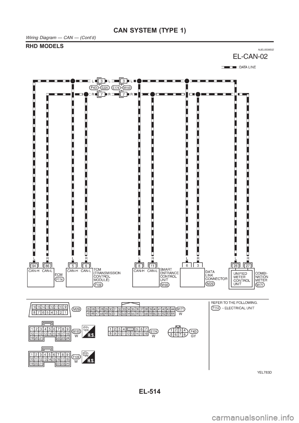
RHD MODELSNJEL0539S02
YEL783D
CAN SYSTEM (TYPE 1)
Wiring Diagram — CAN — (Cont’d)
EL-514