NISSAN NAVARA 2005 Repair Workshop Manual
Manufacturer: NISSAN, Model Year: 2005, Model line: NAVARA, Model: NISSAN NAVARA 2005Pages: 3171, PDF Size: 49.59 MB
Page 521 of 3171

SYSTEM DESCRIPTION
AV-33
C
D
E
F
G
H
I
J
L
MA
B
AV
CAN CommunicationEKS00Q6A
SYSTEM DESCRIPTION
CAN (Controller Area Network) is a serial communication line for real time application. It is an on-vehicle mul-
tiplex communication line with high data communication speed and excellent error detection ability. Many elec-
tronic control units are equipped onto a vehicle, and each control unit shares information and links with other
control units during operation (not independent). In CAN communication, control units are connected with 2
communication lines (CAN H line, CAN L line) allowing a high rate of information transmission with less wiring.
Each control unit transmits/receives data but selectively reads required data only. Refer toLAN-30, "
CAN
Communication Unit".
Page 522 of 3171
AV-34
TERMINALS AND REFERENCE VALUE FOR CONTROL UNIT
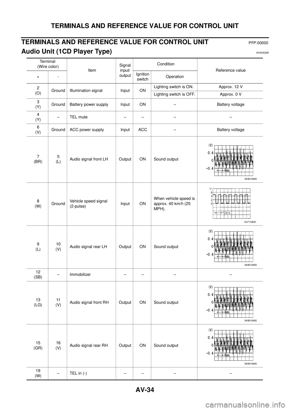
TERMINALS AND REFERENCE VALUE FOR CONTROL UNIT
PFP:00000
Audio Unit (1CD Player Type)EKS00Q6B
Te r m i n a l
(Wire color)
ItemSignal
input/
outputCondition
Reference value
+-Ignition
switchOperation
2
(O)Ground Illumination signal Input ONLighting switch is ON. Approx. 12 V
Lighting switch is OFF. Approx. 0 V
3
(Y)Ground Battery power supply Input ON – Battery voltage
4
(Y)–TELmute – – – –
6
(V)Ground ACC power supply Input ACC – Battery voltage
7
(BR)5
(L)Audio signal front LH Output ON Sound output
8
(W)GroundVehicle speed signal
(2-pulse)Input ONWhen vehicle speed is
approx. 40 km/h (25
MPH).
9
(L)10
(V)Audio signal rear LH Output ON Sound output
12
(SB)– Immobilizer – – – –
13
(LG)11
(V)Audio signal front RH Output ON Sound output
15
(GR)16
(V)Audio signal rear RH Output ON Sound output
19
(W)–TELin(-) – – – –
SKIB1990E
ELF1080D
SKIB1990E
SKIB1990E
SKIB1990E
Page 523 of 3171
TERMINALS AND REFERENCE VALUE FOR CONTROL UNIT
AV-35
C
D
E
F
G
H
I
J
L
MA
B
AV
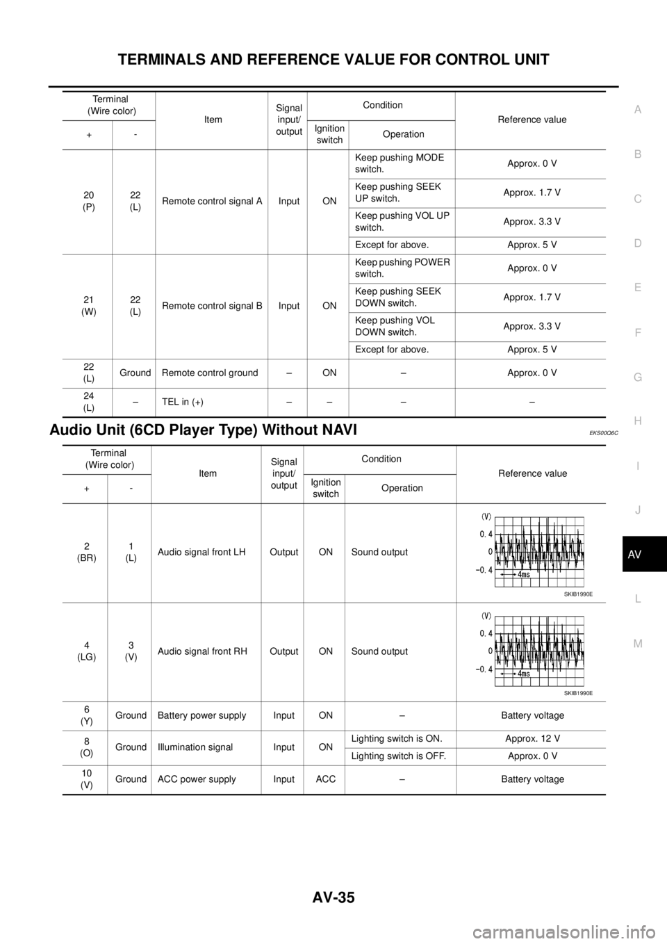
Audio Unit (6CD Player Type) Without NAVIEKS00Q6C
20
(P)22
(L)Remote control signal A Input ONKeep pushing MODE
switch.Approx. 0 V
Keep pushing SEEK
UP switch.Approx. 1.7 V
Keep pushing VOL UP
switch.Approx. 3.3 V
Except for above. Approx. 5 V
21
(W)22
(L)Remote control signal B Input ONKeep pushing POWER
switch.Approx. 0 V
Keep pushing SEEK
DOWN switch.Approx. 1.7 V
Keep pushing VOL
DOWN switch.Approx. 3.3 V
Except for above. Approx. 5 V
22
(L)Ground Remote control ground – ON – Approx. 0 V
24
(L)–TELin(+) – – – – Terminal
(Wire color)
ItemSignal
input/
outputCondition
Reference value
+-Ignition
switchOperation
Terminal
(Wire color)
ItemSignal
input/
outputCondition
Reference value
+-Ignition
switchOperation
2
(BR)1
(L)Audio signal front LH Output ON Sound output
4
(LG)3
(V)Audio signal front RH Output ON Sound output
6
(Y)Ground Battery power supply Input ON – Battery voltage
8
(O)Ground Illumination signal Input ONLighting switch is ON. Approx. 12 V
Lighting switch is OFF. Approx. 0 V
10
(V)Ground ACC power supply Input ACC – Battery voltage
SKIB1990E
SKIB1990E
Page 524 of 3171
AV-36
TERMINALS AND REFERENCE VALUE FOR CONTROL UNIT
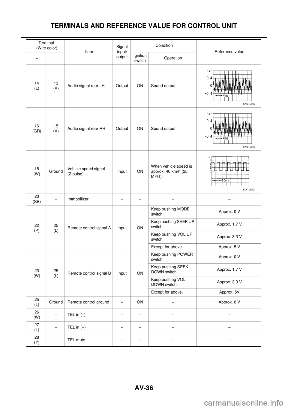
14
(L)13
(V)Audio signal rear LH Output ON Sound output
16
(GR)15
(V)Audio signal rear RH Output ON Sound output
18
(W)GroundVehicle speed signal
(2-pulse)Input ONWhen vehicle speed is
approx. 40 km/h (25
MPH).
20
(SB)– Immobilizer – – – –
22
(P)25
(L)Remote control signal A Input ONKeep pushing MODE
switch.Approx. 0 V
Keep pushing SEEK UP
switch.Approx. 1.7 V
Keep pushing VOL UP
switch.Approx. 3.3 V
Except for above. Approx. 5 V
23
(W)25
(L)Remote control signal B Input ONKeep pushing POWER
switch.Approx. 0 V
Keep pushing SEEK
DOWN switch.Approx. 1.7 V
Keep pushing VOL
DOWN switch.Approx. 3.3 V
Except for above. Approx. 5V
25
(L)Ground Remote control ground – ON – Approx. 0 V
26
(W)–TELin(–) – – – –
27
(L)–TELin(+) – – – –
28
(Y)–TELmute – – – – Terminal
(Wire color)
ItemSignal
input/
outputCondition
Reference value
+-Ignition
switchOperation
SKIB1990E
SKIB1990E
ELF1080D
Page 525 of 3171
TERMINALS AND REFERENCE VALUE FOR CONTROL UNIT
AV-37
C
D
E
F
G
H
I
J
L
MA
B
AV
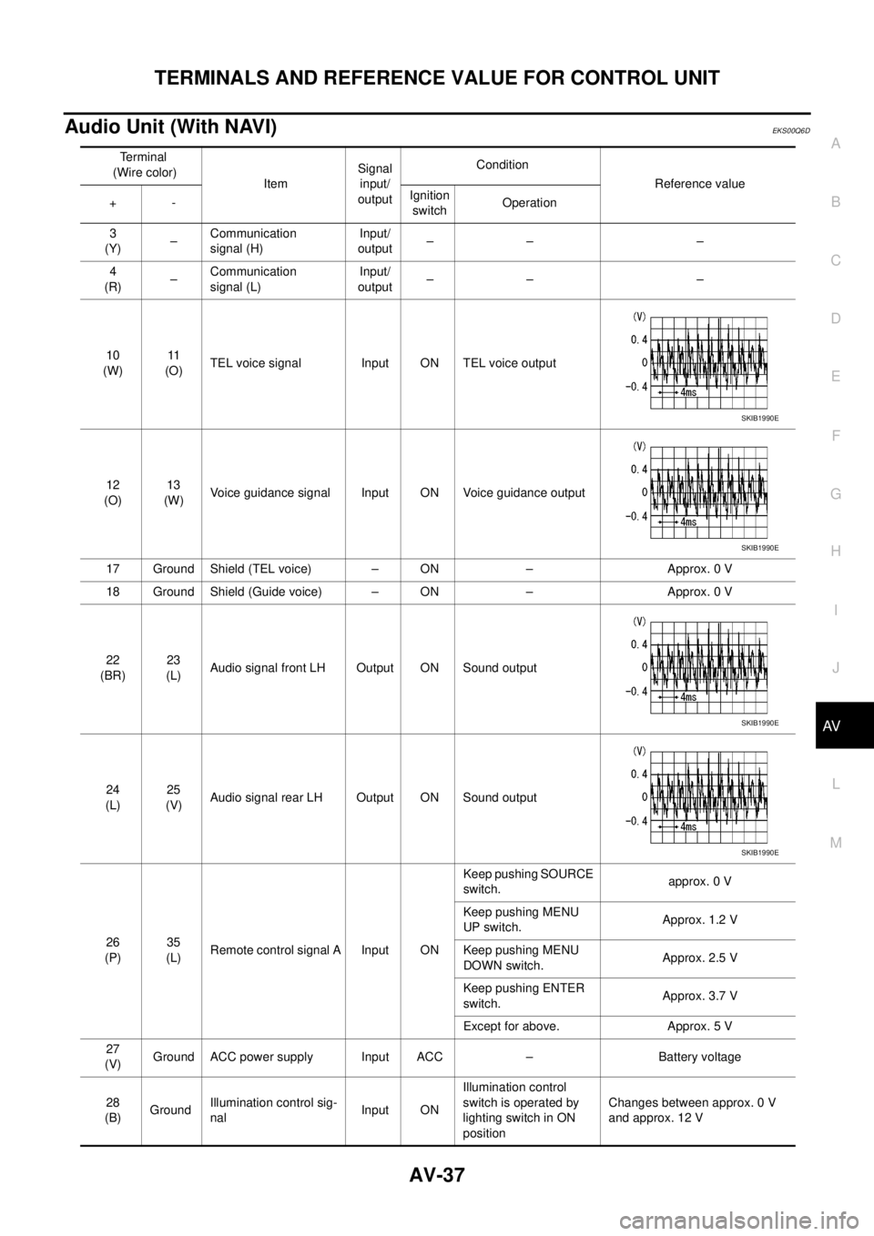
Audio Unit (With NAVI)EKS00Q6D
Terminal
(Wire color)
ItemSignal
input/
outputCondition
Reference value
+-Ignition
switchOperation
3
(Y)–Communication
signal (H)Input/
output–– –
4
(R)–Communication
signal (L)Input/
output–– –
10
(W)11
(O)TEL voice signal Input ON TEL voice output
12
(O)13
(W)Voice guidance signal Input ON Voice guidance output
17 Ground Shield (TEL voice) – ON – Approx. 0 V
18 Ground Shield (Guide voice) – ON – Approx. 0 V
22
(BR)23
(L)Audio signal front LH Output ON Sound output
24
(L)25
(V)Audio signal rear LH Output ON Sound output
26
(P)35
(L)Remote control signal A Input ONKeep pushing SOURCE
switch.approx. 0 V
Keep pushing MENU
UP switch.Approx. 1.2 V
Keep pushing MENU
DOWN switch.Approx. 2.5 V
Keep pushing ENTER
switch.Approx. 3.7 V
Except for above. Approx. 5 V
27
(V)Ground ACC power supply Input ACC – Battery voltage
28
(B)GroundIllumination control sig-
nalInput ONIllumination control
switch is operated by
lighting switch in ON
positionChanges between approx. 0 V
and approx. 12 V
SKIB1990E
SKIB1990E
SKIB1990E
SKIB1990E
Page 526 of 3171
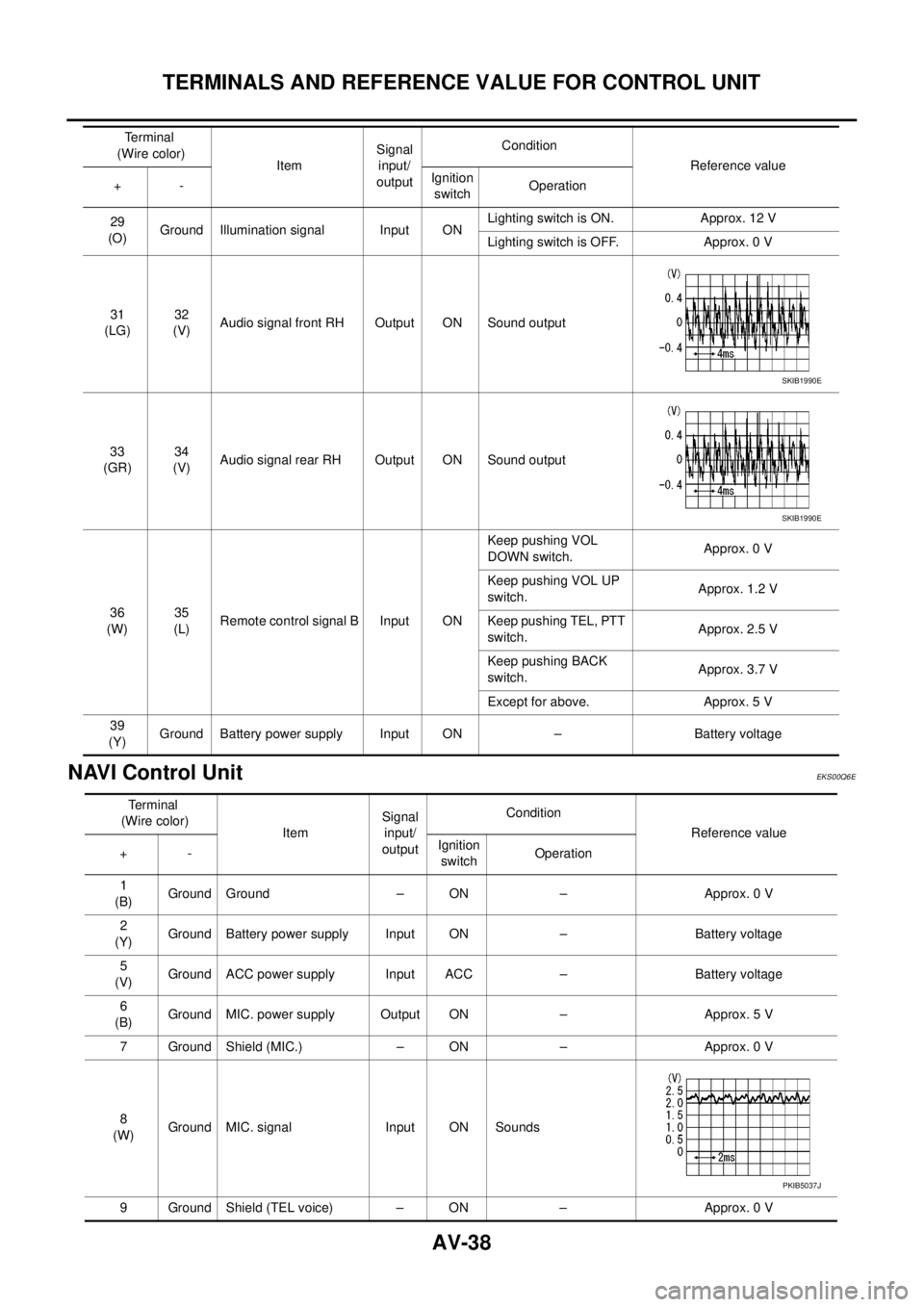
AV-38
TERMINALS AND REFERENCE VALUE FOR CONTROL UNIT
NAVI Control Unit
EKS00Q6E
29
(O)Ground Illumination signal Input ONLighting switch is ON. Approx. 12 V
Lighting switch is OFF. Approx. 0 V
31
(LG)32
(V)Audio signal front RH Output ON Sound output
33
(GR)34
(V)Audio signal rear RH Output ON Sound output
36
(W)35
(L)Remote control signal B Input ONKeep pushing VOL
DOWN switch.Approx. 0 V
Keep pushing VOL UP
switch.Approx. 1.2 V
Keep pushing TEL, PTT
switch.Approx. 2.5 V
Keep pushing BACK
switch.Approx. 3.7 V
Except for above. Approx. 5 V
39
(Y)Ground Battery power supply Input ON – Battery voltage Terminal
(Wire color)
ItemSignal
input/
outputCondition
Reference value
+-Ignition
switchOperation
SKIB1990E
SKIB1990E
Terminal
(Wire color)
ItemSignal
input/
outputCondition
Reference value
+-Ignition
switchOperation
1
(B)Ground Ground – ON – Approx. 0 V
2
(Y)Ground Battery power supply Input ON – Battery voltage
5
(V)Ground ACC power supply Input ACC – Battery voltage
6
(B)Ground MIC. power supply Output ON – Approx. 5 V
7 Ground Shield (MIC.) – ON – Approx. 0 V
8
(W)Ground MIC. signal Input ON Sounds
9 Ground Shield (TEL voice) – ON – Approx. 0 V
PKIB5037J
Page 527 of 3171
TERMINALS AND REFERENCE VALUE FOR CONTROL UNIT
AV-39
C
D
E
F
G
H
I
J
L
MA
B
AV
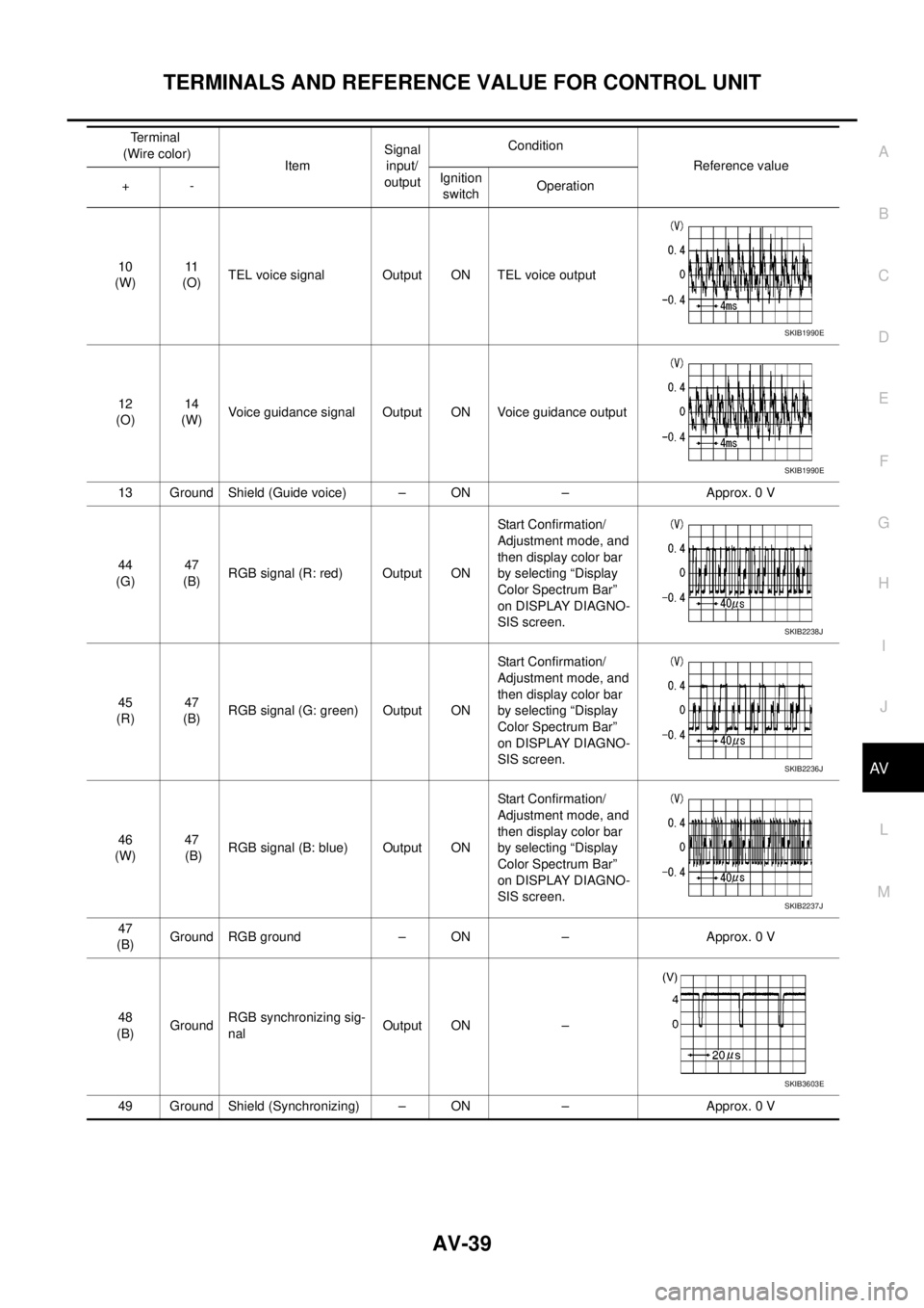
10
(W)11
(O)TEL voice signal Output ON TEL voice output
12
(O)14
(W)Voice guidance signal Output ON Voice guidance output
13 Ground Shield (Guide voice) – ON – Approx. 0 V
44
(G)47
(B)RGB signal (R: red) Output ONStart Confirmation/
Adjustment mode, and
then display color bar
by selecting “Display
Color Spectrum Bar”
on DISPLAY DIAGNO-
SIS screen.
45
(R)47
(B)RGB signal (G: green) Output ONStart Confirmation/
Adjustment mode, and
then display color bar
by selecting “Display
Color Spectrum Bar”
on DISPLAY DIAGNO-
SIS screen.
46
(W)47
(B)RGB signal (B: blue) Output ONStart Confirmation/
Adjustment mode, and
then display color bar
by selecting “Display
Color Spectrum Bar”
on DISPLAY DIAGNO-
SIS screen.
47
(B)Ground RGB ground – ON – Approx. 0 V
48
(B)GroundRGB synchronizing sig-
nalOutput ON –
49 Ground Shield (Synchronizing) – ON – Approx. 0 VTerminal
(Wire color)
ItemSignal
input/
outputCondition
Reference value
+-Ignition
switchOperation
SKIB1990E
SKIB1990E
SKIB2238J
SKIB2236J
SKIB2237J
SKIB3603E
Page 528 of 3171
AV-40
TERMINALS AND REFERENCE VALUE FOR CONTROL UNIT
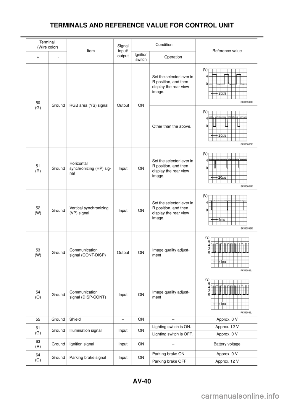
50
(G)Ground RGB area (YS) signal Output ONSet the selector lever in
R position, and then
display the rear view
image.
Other than the above.
51
(R)GroundHorizontal
synchronizing (HP) sig-
nalInput ONSet the selector lever in
R position, and then
display the rear view
image.
52
(W)GroundVertical synchronizing
(VP) signalInput ONSet the selector lever in
R position, and then
display the rear view
image.
53
(W)GroundCommunication
signal (CONT-DISP)Output ONImage quality adjust-
ment
54
(O)GroundCommunication
signal (DISP-CONT)Input ONImage quality adjust-
ment
55 Ground Shield – ON – Approx. 0 V
61
(G)Ground Illumination signal Input ONLighting switch is ON. Approx. 12 V
Lighting switch is OFF. Approx. 0 V
63
(R)Ground Ignition signal Input ON – Battery voltage
64
(G)Ground Parking brake signal Input ONParking brake ON Approx. 0 V
Parking brake OFF Approx. 12 V Terminal
(Wire color)
ItemSignal
input/
outputCondition
Reference value
+-Ignition
switchOperationSKIB3599E
SKIB3600E
SKIB3601E
SKIB3598E
PKIB5039J
PKIB5039J
Page 529 of 3171
TERMINALS AND REFERENCE VALUE FOR CONTROL UNIT
AV-41
C
D
E
F
G
H
I
J
L
MA
B
AV
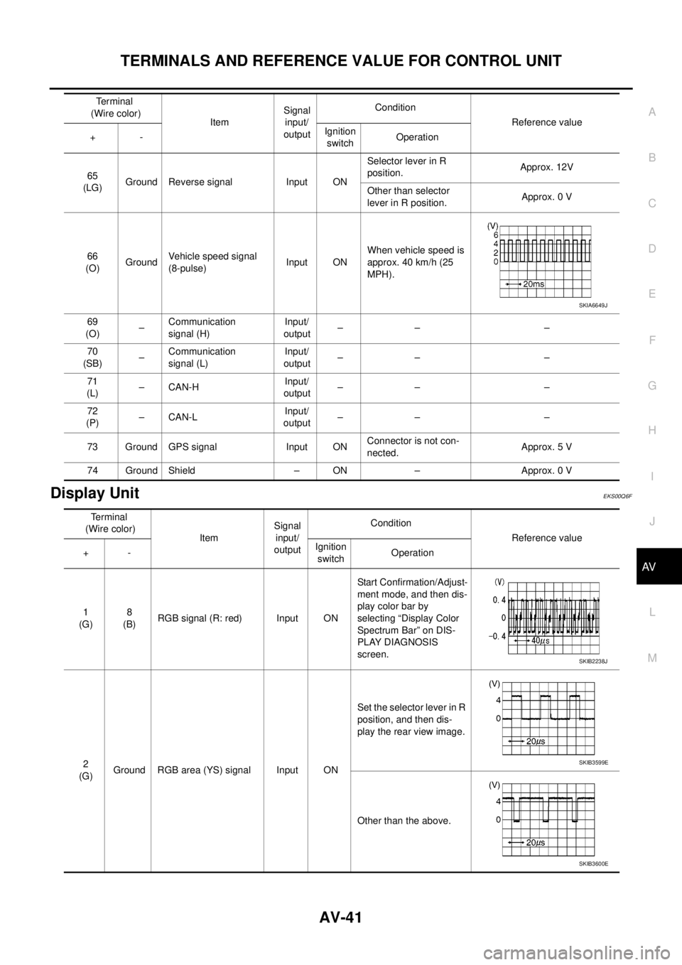
Display UnitEKS00Q6F
65
(LG)Ground Reverse signal Input ONSelector lever in R
position.Approx. 12V
Other than selector
lever in R position.Approx. 0 V
66
(O)GroundVehicle speed signal
(8-pulse)Input ONWhen vehicle speed is
approx. 40 km/h (25
MPH).
69
(O)–Communication
signal (H)Input/
output–– –
70
(SB)–Communication
signal (L)Input/
output–– –
71
(L)–CAN-HInput/
output–– –
72
(P)–CAN-LInput/
output–– –
73 Ground GPS signal Input ONConnector is not con-
nected.Approx. 5 V
74 Ground Shield – ON – Approx. 0 VTerminal
(Wire color)
ItemSignal
input/
outputCondition
Reference value
+-Ignition
switchOperation
SKIA6649J
Terminal
(Wire color)
ItemSignal
input/
outputCondition
Reference value
+-Ignition
switchOperation
1
(G)8
(B)RGB signal (R: red) Input ONStart Confirmation/Adjust-
ment mode, and then dis-
play color bar by
selecting “Display Color
Spectrum Bar” on DIS-
PLAY DIAGNOSIS
screen.
2
(G)Ground RGB area (YS) signal Input ONSet the selector lever in R
position, and then dis-
play the rear view image.
Other than the above.
SKIB2238J
SKIB3599E
SKIB3600E
Page 530 of 3171
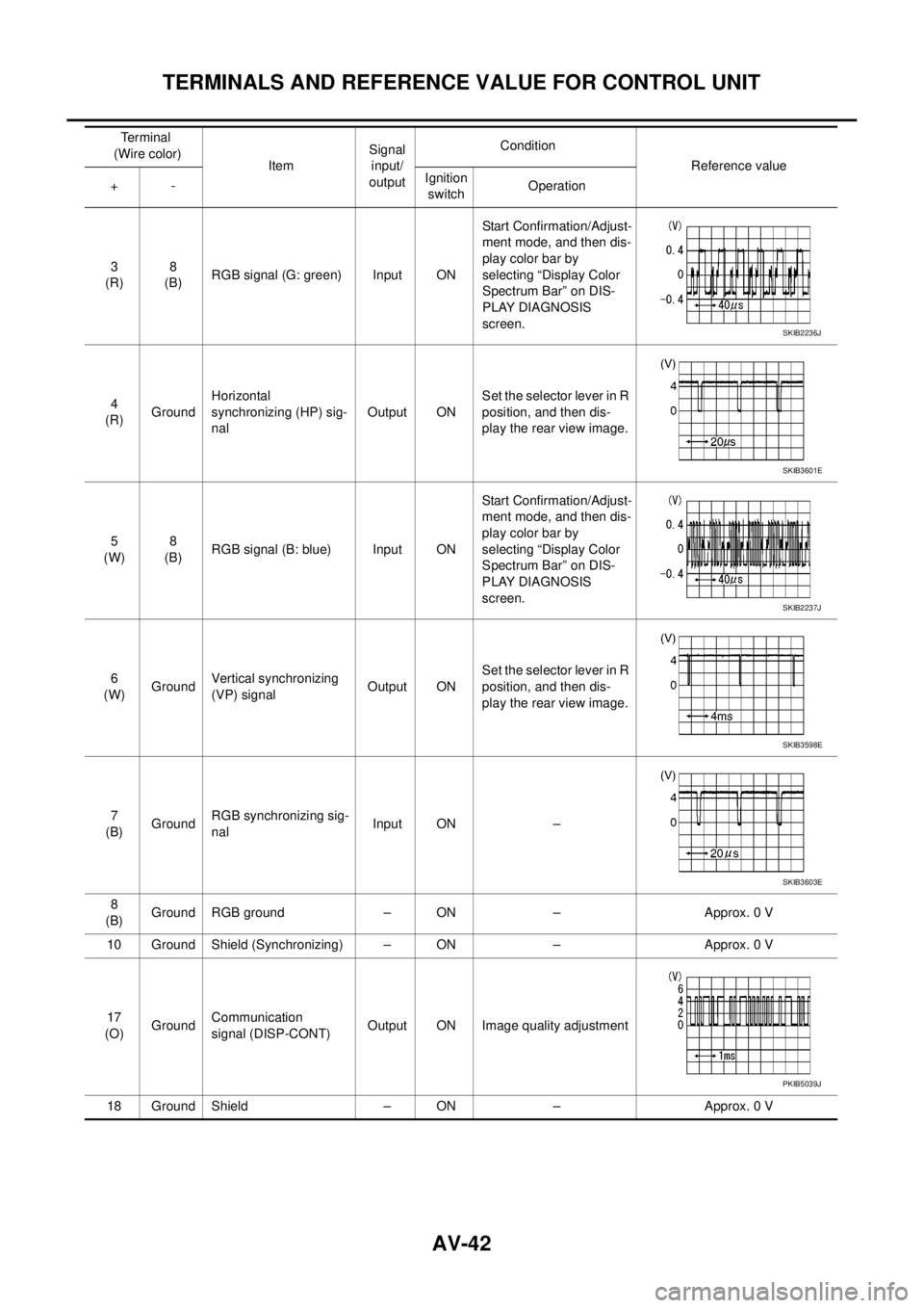
AV-42
TERMINALS AND REFERENCE VALUE FOR CONTROL UNIT
3
(R)8
(B)RGB signal (G: green) Input ONStart Confirmation/Adjust-
ment mode, and then dis-
play color bar by
selecting “Display Color
Spectrum Bar” on DIS-
PLAY DIAGNOSIS
screen.
4
(R)GroundHorizontal
synchronizing (HP) sig-
nalOutput ONSet the selector lever in R
position, and then dis-
play the rear view image.
5
(W)8
(B)RGB signal (B: blue) Input ONStart Confirmation/Adjust-
ment mode, and then dis-
play color bar by
selecting “Display Color
Spectrum Bar” on DIS-
PLAY DIAGNOSIS
screen.
6
(W)GroundVertical synchronizing
(VP) signalOutput ONSet the selector lever in R
position, and then dis-
play the rear view image.
7
(B)GroundRGB synchronizing sig-
nalInput ON –
8
(B)Ground RGB ground – ON – Approx. 0 V
10 Ground Shield (Synchronizing) – ON – Approx. 0 V
17
(O)GroundCommunication
signal (DISP-CONT)Output ON Image quality adjustment
18 Ground Shield – ON – Approx. 0 VTerminal
(Wire color)
ItemSignal
input/
outputCondition
Reference value
+-Ignition
switchOperation
SKIB2236J
SKIB3601E
SKIB2237J
SKIB3598E
SKIB3603E
PKIB5039J