NISSAN NAVARA 2005 Repair Workshop Manual
Manufacturer: NISSAN, Model Year: 2005, Model line: NAVARA, Model: NISSAN NAVARA 2005Pages: 3171, PDF Size: 49.59 MB
Page 561 of 3171
REMOVAL AND INSTALLATION
AV-73
C
D
E
F
G
H
I
J
L
MA
B
AV
REMOVAL AND INSTALLATIONPFP:00000
Auido Unit (1CD Player Type)EKS00Q6U
REMOVAL
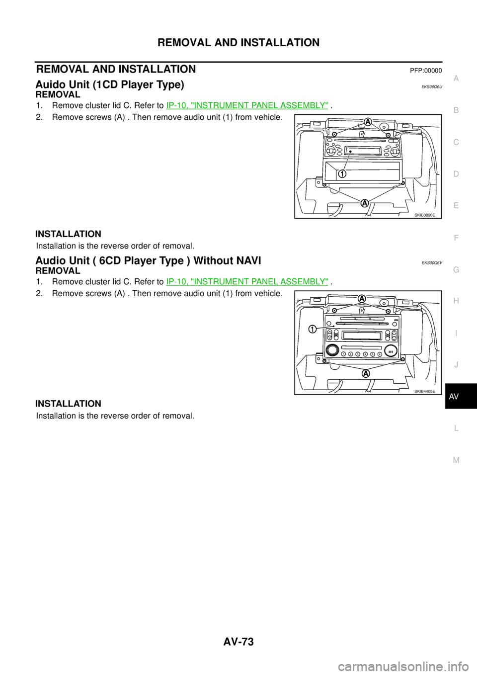
1. Remove cluster lid C. Refer toIP-10, "INSTRUMENT PANEL ASSEMBLY".
2. Remove screws (A) . Then remove audio unit (1) from vehicle.
INSTALLATION
Installation is the reverse order of removal.
Audio Unit ( 6CD Player Type ) Without NAVIEKS00Q6V
REMOVAL
1. Remove cluster lid C. Refer toIP-10, "INSTRUMENT PANEL ASSEMBLY".
2. Remove screws (A) . Then remove audio unit (1) from vehicle.
INSTALLATION
Installation is the reverse order of removal.
SKIB3890E
SKIB4405E
Page 562 of 3171
AV-74
REMOVAL AND INSTALLATION
Audio Unit (6CD Player Type) With NAVI
EKS00Q6W
REMOVAL
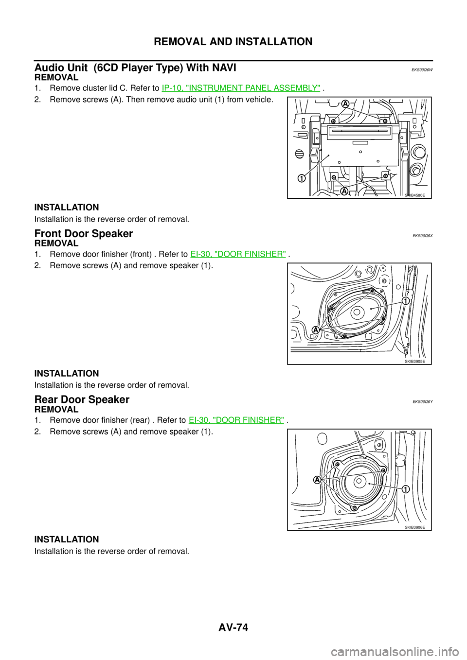
1. Remove cluster lid C. Refer toIP-10, "INSTRUMENT PANEL ASSEMBLY".
2. Remove screws (A). Then remove audio unit (1) from vehicle.
INSTALLATION
Installation is the reverse order of removal.
Front Door SpeakerEKS00Q6X
REMOVAL
1. Remove door finisher (front) . Refer toEI-30, "DOOR FINISHER".
2. Remove screws (A) and remove speaker (1).
INSTALLATION
Installation is the reverse order of removal.
Rear Door SpeakerEKS00Q6Y
REMOVAL
1. Remove door finisher (rear) . Refer toEI-30, "DOOR FINISHER".
2. Remove screws (A) and remove speaker (1).
INSTALLATION
Installation is the reverse order of removal.
SKIB4580E
SKIB3905E
SKIB3906E
Page 563 of 3171
REMOVAL AND INSTALLATION
AV-75
C
D
E
F
G
H
I
J
L
MA
B
AV
Tw e e t e rEKS00Q6Z
REMOVAL
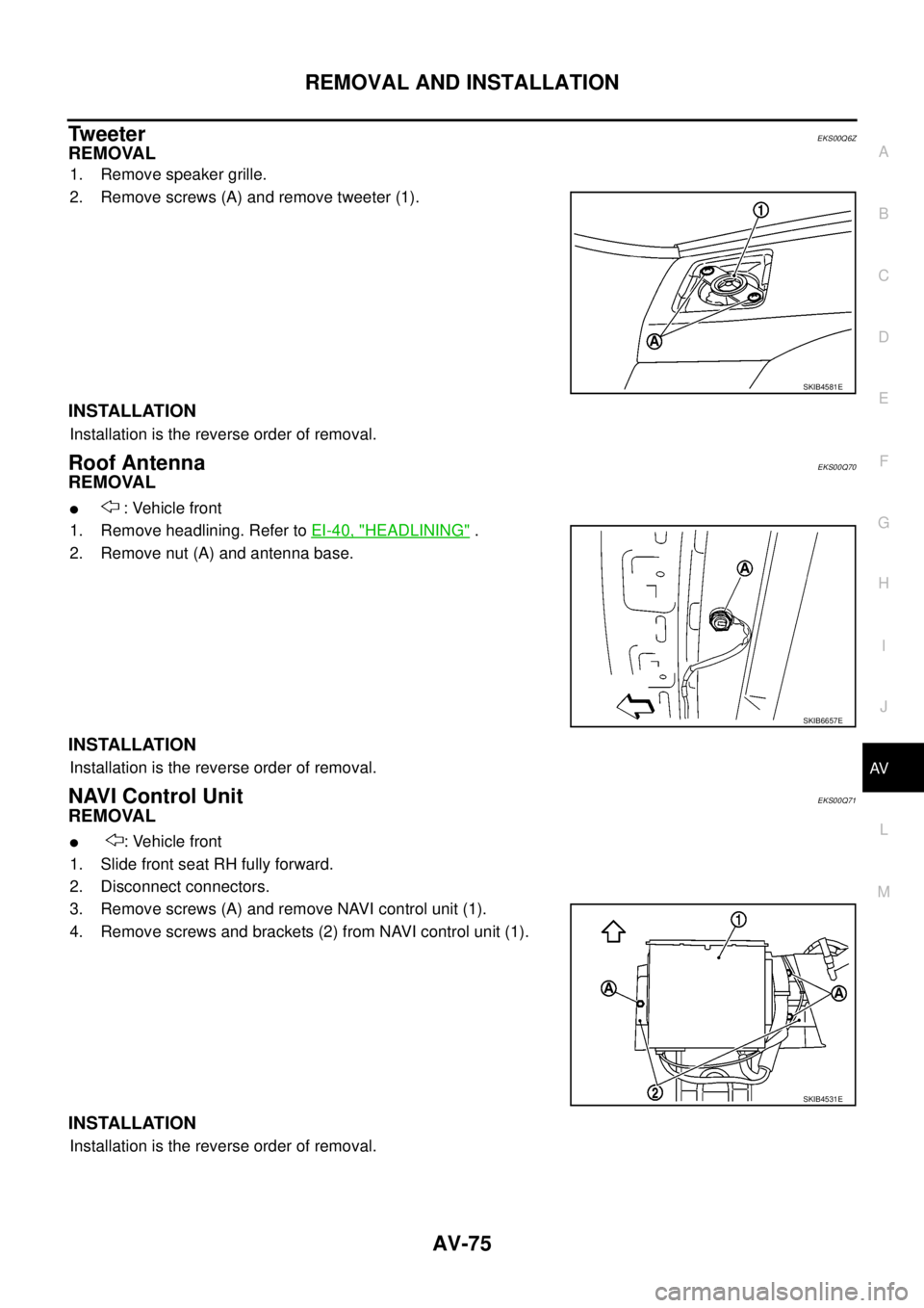
1. Remove speaker grille.
2. Remove screws (A) and remove tweeter (1).
INSTALLATION
Installation is the reverse order of removal.
Roof AntennaEKS00Q70
REMOVAL
l: Vehicle front
1. Remove headlining. Refer toEI-40, "
HEADLINING".
2. Remove nut (A) and antenna base.
INSTALLATION
Installation is the reverse order of removal.
NAVI Control UnitEKS00Q71
REMOVAL
l: Vehicle front
1. Slide front seat RH fully forward.
2. Disconnect connectors.
3. Remove screws (A) and remove NAVI control unit (1).
4. Remove screws and brackets (2) from NAVI control unit (1).
INSTALLATION
Installation is the reverse order of removal.
SKIB4581E
SKIB6657E
SKIB4531E
Page 564 of 3171
AV-76
REMOVAL AND INSTALLATION
GPS Antenna
EKS00Q72
REMOVAL
l: Vehicle front
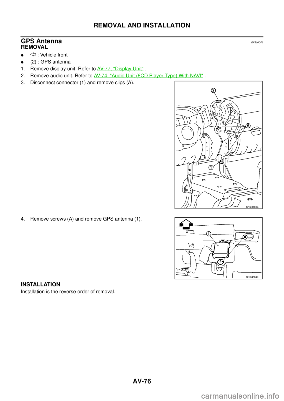
l(2) : GPS antenna
1. Remove display unit. Refer toAV-77, "
Display Unit".
2. Remove audio unit. Refer toAV-74, "
Audio Unit (6CD Player Type) With NAVI".
3. Disconnect connector (1) and remove clips (A).
4. Remove screws (A) and remove GPS antenna (1).
INSTALLATION
Installation is the reverse order of removal.
SKIB4583E
SKIB4584E
Page 565 of 3171
REMOVAL AND INSTALLATION
AV-77
C
D
E
F
G
H
I
J
L
MA
B
AV
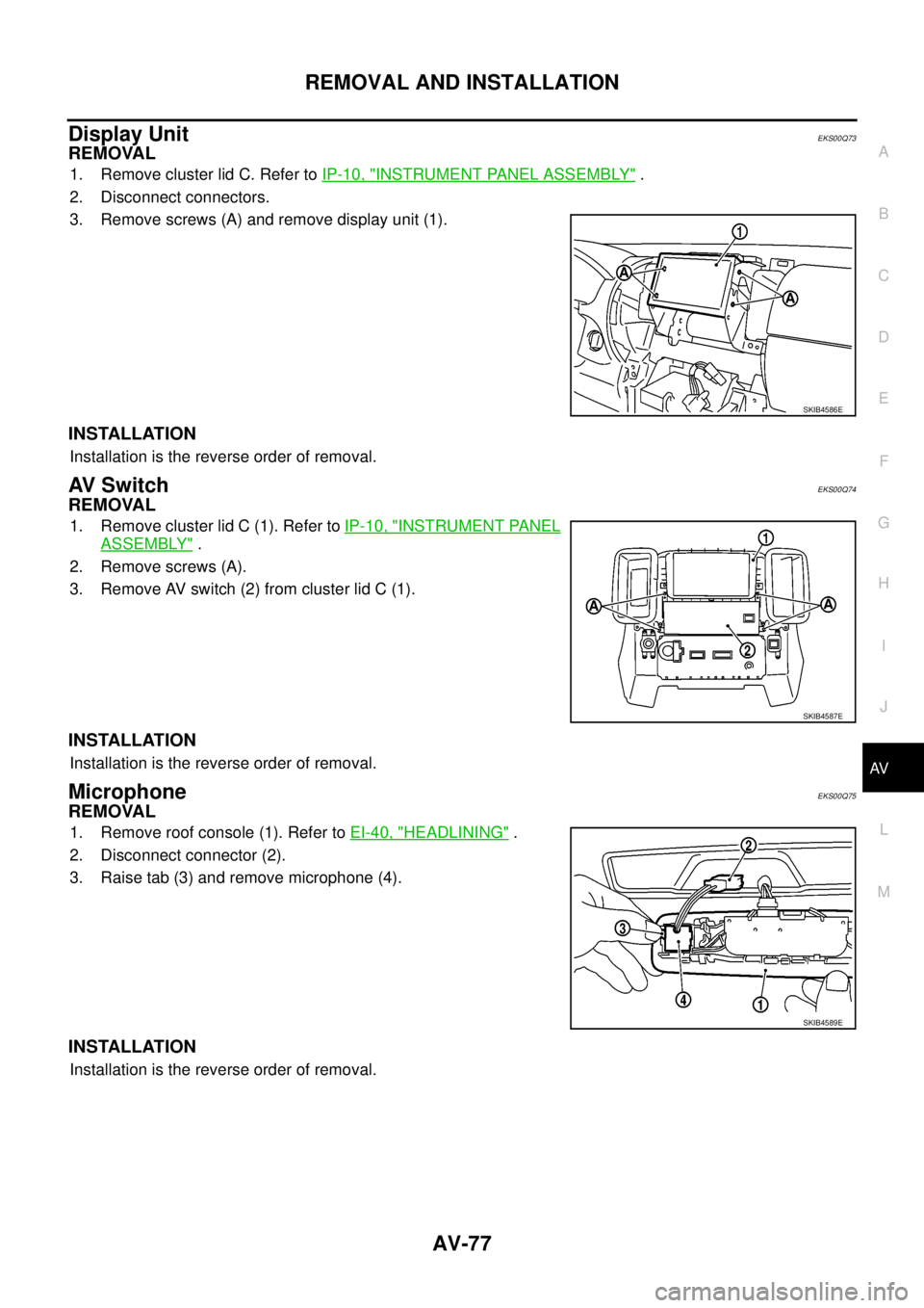
Display UnitEKS00Q73
REMOVAL
1. Remove cluster lid C. Refer toIP-10, "INSTRUMENT PANEL ASSEMBLY".
2. Disconnect connectors.
3. Remove screws (A) and remove display unit (1).
INSTALLATION
Installation is the reverse order of removal.
AV S w i t c hEKS00Q74
REMOVAL
1. Remove cluster lid C (1). Refer toIP-10, "INSTRUMENT PANEL
ASSEMBLY".
2. Remove screws (A).
3. Remove AV switch (2) from cluster lid C (1).
INSTALLATION
Installation is the reverse order of removal.
MicrophoneEKS00Q75
REMOVAL
1. Remove roof console (1). Refer toEI-40, "HEADLINING".
2. Disconnect connector (2).
3. Raise tab (3) and remove microphone (4).
INSTALLATION
Installation is the reverse order of removal.
SKIB4586E
SKIB4587E
SKIB4589E
Page 566 of 3171

AV-78
REMOVAL AND INSTALLATION
Page 567 of 3171
BCS-1
BODY CONTROL SYSTEM
K ELECTRICAL
CONTENTS
C
D
E
F
G
H
I
J
L
M
SECTIONBCS
A
B
BCS
BODY CONTROL SYSTEM
PRECAUTIONS .......................................................... 2
Precautions for Supplemental Restraint System
(SRS)“AIRBAG”and“SEATBELTPRE-TEN-
SIONER” .................................................................. 2
BCM (BODY CONTROL MODULE) ........................... 3
System Description .................................................. 3
BCM FUNCTION ................................................... 3
COMBINATION SWITCH READING FUNCTION..... 3
CAN COMMUNICATION CONTROL .................... 6
BCM STATUS CONTROL ..................................... 7
SYSTEMS CONTROLLED BY BCM DIRECTLY..... 8
SYSTEMS CONTROLLED BY BCM AND IPDM
E/R ........................................................................ 8
SYSTEMS CONTROLLED BY BCM AND COM-
BINATION METER ................................................ 8
MAJOR COMPONENTS AND CONTROL SYS-TEM ....................................................................... 9
CAN Communication System Description ................ 9
Schematic ............................................................... 10
LHD MODELS ..................................................... 10
RHD MODELS .................................................... 12
CONSULT-II Function (BCM) ................................. 14
CONSULT–II INSPECTION PROCEDURE ......... 14
ITEMS OF EACH PART ...................................... 15
WORK SUPPORT ............................................... 15
CAN Communication Inspection Using CONSULT-
II (Self-Diagnosis) ................................................... 16
Configuration .......................................................... 17
Removal and Installation of BCM ........................... 17
REMOVAL ........................................................... 17
INSTALLATION ................................................... 17
Page 568 of 3171
BCS-2
PRECAUTIONS
PRECAUTIONS
PFP:00001
Precautions for Supplemental Restraint System (SRS) “AIR BAG” and “SEAT
BELT PRE-TENSIONER”
EKS00N1P
The Supplemental Restraint System such as “AIR BAG” and “SEAT BELT PRE-TENSIONER”, used along
with a front seat belt, helps to reduce the risk or severity of injury to the driver and front passenger for certain
types of collision. Information necessary to service the system safely is included in the SRS and SB section of
this Service Manual.
WARNING:
lTo avoid rendering the SRS inoperative, which could increase the risk of personal injury or death
in the event of a collision which would result in air bag inflation, all maintenance must be per-
formed by an authorized NISSAN/INFINITI dealer.
lImproper maintenance, including incorrect removal and installation of the SRS, can lead to per-
sonal injury caused by unintentional activation of the system. For removal of Spiral Cable and Air
Bag Module, see the SRS section.
lDo not use electrical test equipment on any circuit related to the SRS unless instructed to in this
Service Manual. SRS wiring harnesses can be identified by yellow and/or orange harnesses or
harness connectors.
Page 569 of 3171
BCM (BODY CONTROL MODULE)
BCS-3
C
D
E
F
G
H
I
J
L
MA
B
BCS
BCM (BODY CONTROL MODULE)PFP:284B2
System DescriptionEKS00PA1
lBCM (Body Control Module) controls the operation of various electrical units installed on the vehicle.
BCM FUNCTION
BCM has a combination switch reading function for reading the operation of combination switches (light, wiper
washer, turn signal) in addition to the function for controlling the operation of various electrical components.
Also, it functions as an interface that receives signals from the front air control, and sends signals to ECM
using CAN communication.
COMBINATION SWITCH READING FUNCTION
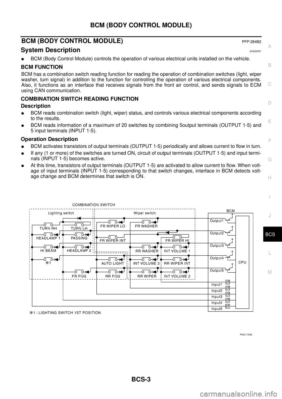
Description
lBCM reads combination switch (light, wiper) status, and controls various electrical components according
to the results.
lBCM reads information of a maximum of 20 switches by combining 5output terminals (OUTPUT 1-5) and
5 input terminals (INPUT 1-5).
Operation Description
lBCM activates transistors of output terminals (OUTPUT 1-5) periodically and allows current to flow in turn.
lIf any (1 or more) of the switches are turned ON, circuit of output terminals (OUTPUT 1-5) and input termi-
nals (INPUT 1-5) becomes active.
lAt this time, transistors of output terminals (OUTPUT 1-5) are activated to allow current to flow. When volt-
age of input terminals (INPUT 1-5) corresponding to that switch changes, interface in BCM detects volt-
age change and BCM determines that switch is ON.
PKIC1724E
Page 570 of 3171
BCS-4
BCM (BODY CONTROL MODULE)
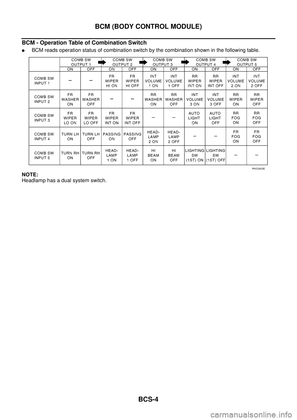
BCM - Operation Table of Combination Switch
lBCM reads operation status of combination switch by the combination shown in the following table.
NOTE:
Headlamp has a dual system switch.
PKIC0420E