NISSAN NAVARA 2005 Repair Workshop Manual
Manufacturer: NISSAN, Model Year: 2005, Model line: NAVARA, Model: NISSAN NAVARA 2005Pages: 3171, PDF Size: 49.59 MB
Page 531 of 3171
TERMINALS AND REFERENCE VALUE FOR CONTROL UNIT
AV-43
C
D
E
F
G
H
I
J
L
MA
B
AV
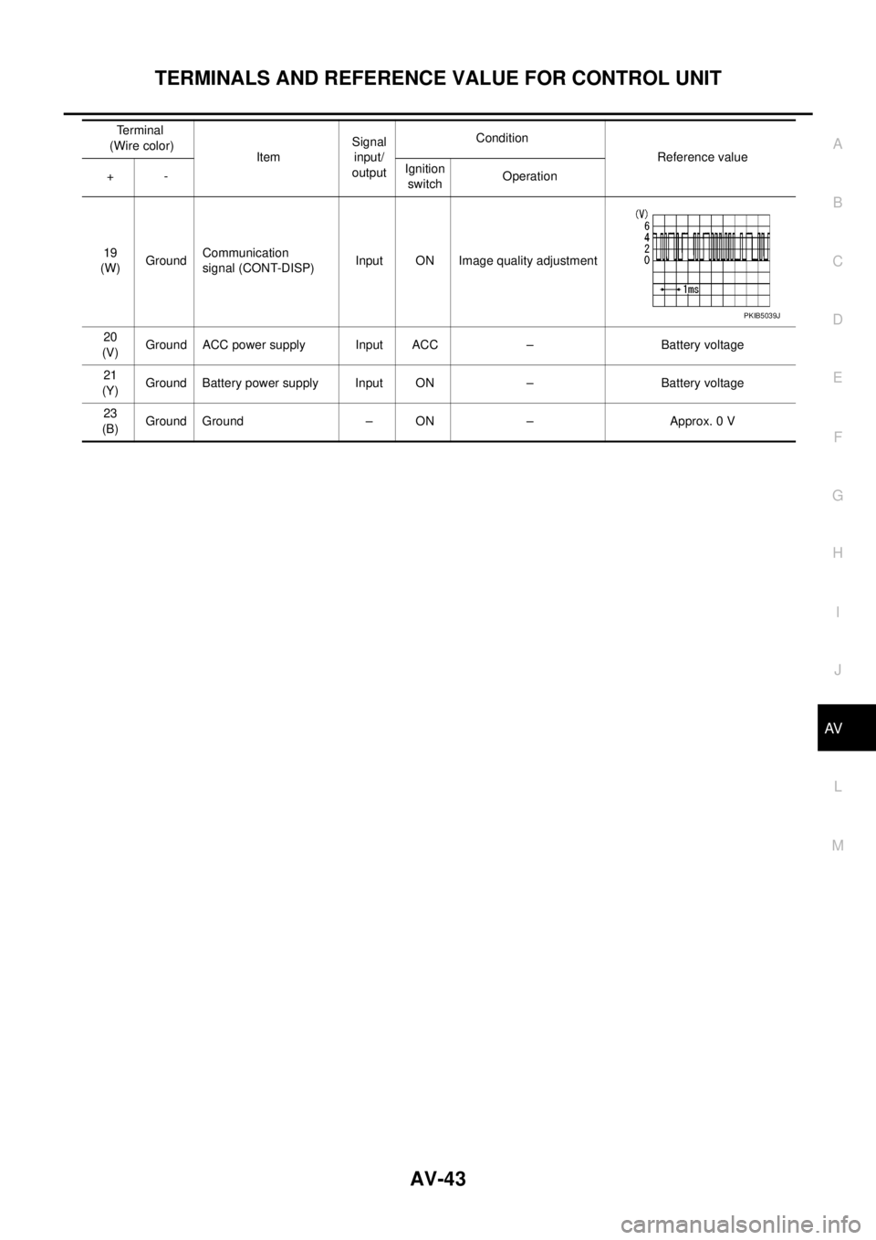
19
(W)GroundCommunication
signal (CONT-DISP)Input ON Image quality adjustment
20
(V)Ground ACC power supply Input ACC – Battery voltage
21
(Y)Ground Battery power supply Input ON – Battery voltage
23
(B)Ground Ground – ON – Approx. 0 V Terminal
(Wire color)
ItemSignal
input/
outputCondition
Reference value
+-Ignition
switchOperation
PKIB5039J
Page 532 of 3171

AV-44
DIAGNOSIS SYSTEM
DIAGNOSIS SYSTEM
PFP:00000
Navigation System Diagnosis FunctionEKS00Q6H
lThere are 2 diagnosis functions (on board diagnosis and diagnosis using CONSULT-II), and it is neces-
sary to use them properly according to the condition. If the on board diagnosis starts, perform diagnosis
with on board diagnosis. If the on board diagnosis does not start (the cause being that the system is not
started, the switch operation is not activated, etc.), perform diagnosis using CONSULT-II.
lAt on board diagnosis, the NAVI control unit diagnosis function starts by switch operation and the NAVI
control unit performs the diagnosis for each unit of system.
lAt diagnosis using CONSULT-II, the NAVI control unit diagnosis function starts by the communication
between CONSULT-II and NAVI control unit, and the NAVI control unit performs the diagnosis for each
unit of system.
On Bord Self-Diagnosis FunctionEKS00Q6I
DESCRIPTION
lThe on board diagnosis function has a self-diagnosis mode for performing trouble diagnosis automatically
and a Confirmation/Adjustment mode for operating manually.
lSelf-diagnosis mode performs the diagnosis at NAVI control unit, connections between each unit that
composes the system, and connections between NAVI control unit and GPS antenna. It displays the
results on the display.
lConfirmation/Adjustment mode is used to monitor the vehicle signals requiring operation and judgement
by a technician (malfunctions that cannot be automatically judged by the system), the confirmation/adjust-
ment of setting value, the error history of system, and the communication condition of system.
DIAGNOSIS ITEM
Mode Description
Self Diagnosis
lNAVI control unit diagnosis (DVD-ROM drive will not be diagnosed when
no map DVD-ROM is in it.)
lThe connection diagnosis between NAVI control unit and GPS antenna
and the connection diagnosis between NAVI control unit and each unit
can be performed.
Confirma-
tion/Adjust-
mentDisplay DiagnosisThe tint can be confirmed by the color spectrum bar display. The shading
of color can be confirmed by the gradation bar display.
Vehicle SignalsDiagnosis of signals can be performed for vehicle speed, parking brake,
lights, ignition (ignition switch), and reverse.
Speaker Test The connection of a speaker can be confirmed by test tone.
NavigationSteering Angle
AdjustmentWhen there is a difference between the actual turning angle and the vehi-
cle mark turning angle, it can be adjusted.
Speed CalibrationWhen there is a difference between the current location mark and the
actual location, it can be adjusted.
Error HistoryThe system malfunction and its frequency that occurred in the past are dis-
played. When the malfunctioning item is selected, the time and place that
the selected malfunction last occurred are displayed.
Vehicle CAN Diagnosis The transmitting/receiving of CAN communication can be monitored.
AV COMM DiagnosisThe communication condition of each unit that composes the system can
be monitored.
Handsfree PhoneEach setting of hands-free volume adjustment, voice microphone test,
delete hands-free memory can be performed.
Bluetooth Passkey and device name can be confirmed/changed.
Delete Unit Commection Log The connection history and error history of unit can be deleted.
Page 533 of 3171
DIAGNOSIS SYSTEM
AV-45
C
D
E
F
G
H
I
J
L
MA
B
AV
OPERATION PROCEDURE
1. Start engine.
2. Turn the audio OFF.
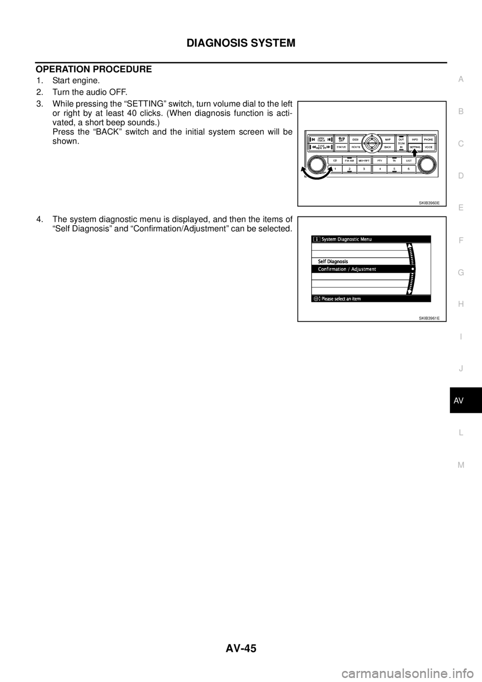
3. While pressing the “SETTING” switch, turn volume dial to the left
or right by at least 40 clicks. (When diagnosis function is acti-
vated, a short beep sounds.)
Press the “BACK” switch and the initial system screen will be
shown.
4. The system diagnostic menu is displayed, and then the items of
“Self Diagnosis” and “Confirmation/Adjustment” can be selected.
SKIB3960E
SKIB3961E
Page 534 of 3171
AV-46
DIAGNOSIS SYSTEM
Self Diagnosis Mode
EKS00Q6J
1. Start the diagnosis function, and then select “Self Diagnosis”.
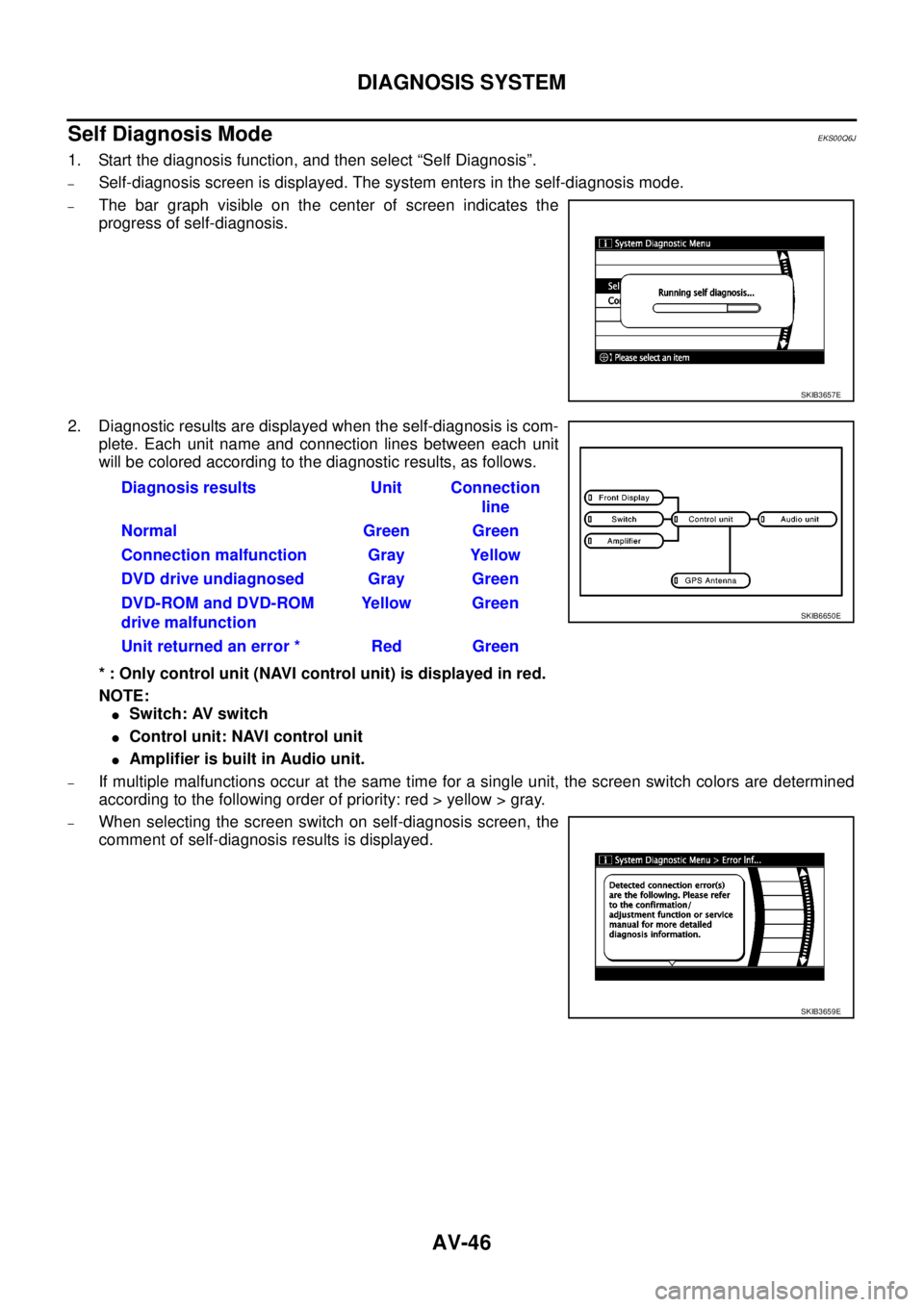
–Self-diagnosis screen is displayed. The system enters in the self-diagnosis mode.
–The bar graph visible on the center of screen indicates the
progress of self-diagnosis.
2. Diagnostic results are displayed when the self-diagnosis is com-
plete. Each unit name and connection lines between each unit
will be colored according to the diagnostic results, as follows.
* : Only control unit (NAVI control unit) is displayed in red.
NOTE:
lSwitch: AV switch
lControl unit: NAVI control unit
lAmplifier is built in Audio unit.
–If multiple malfunctions occur at the same time for a single unit, the screen switch colors are determined
according to the following order of priority: red > yellow > gray.
–When selecting the screen switch on self-diagnosis screen, the
comment of self-diagnosis results is displayed.
SKIB3657E
Diagnosis results Unit Connection
line
Normal Green Green
Connection malfunction Gray Yellow
DVD drive undiagnosed Gray Green
DVD-ROM and DVD-ROM
drive malfunctionYellow Green
Unit returned an error * Red Green
SKIB6650E
SKIB3659E
Page 535 of 3171
DIAGNOSIS SYSTEM
AV-47
C
D
E
F
G
H
I
J
L
MA
B
AV
ERROR DETECTION RANGE OF SELF-DIAGNOSIS MODE
lSelf-diagnosis mode can perform the connection condition diagnosis of communication circuit between
NAVI control unit and each unit and the NAVI control unit diagnosis.
lSince the start condition of diagnosis function is switch operation, if the malfunction is detected in the
communication circuit between NAVI control unit and AV switch, on board diagnosis function cannot be
started.
DIAGNOSIS RESULTS
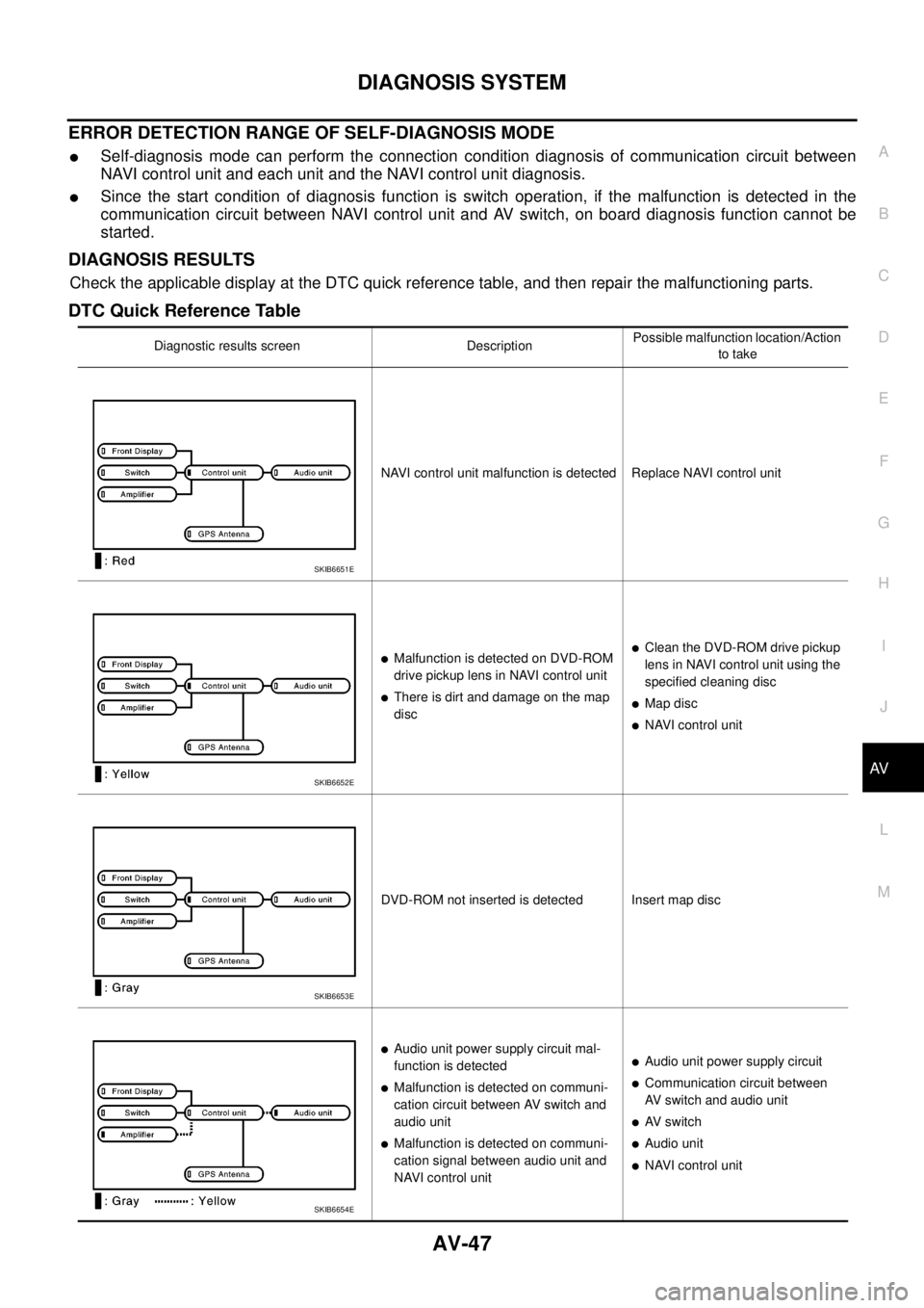
Check the applicable display at the DTC quick reference table, and then repair the malfunctioning parts.
DTC Quick Reference Table
Diagnostic results screen DescriptionPossible malfunction location/Action
to take
NAVI control unit malfunction is detected Replace NAVI control unit
lMalfunction is detected on DVD-ROM
drive pickup lens in NAVI control unit
lThere is dirt and damage on the map
disc
lClean the DVD-ROM drive pickup
lens in NAVI control unit using the
specified cleaning disc
lMap disc
lNAVI control unit
DVD-ROM not inserted is detected Insert map disc
lAudio unit power supply circuit mal-
function is detected
lMalfunction is detected on communi-
cation circuit between AV switch and
audio unit
lMalfunction is detected on communi-
cation signal between audio unit and
NAVI control unit
lAudio unit power supply circuit
lCommunication circuit between
AV switch and audio unit
lAV s w i t c h
lAudio unit
lNAVI control unit
SKIB6651E
SKIB6652E
SKIB6653E
SKIB6654E
Page 536 of 3171
AV-48
DIAGNOSIS SYSTEM
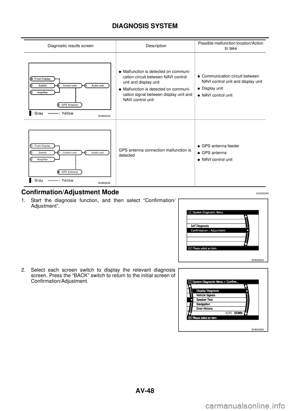
Confirmation/Adjustment Mode
EKS00Q6K
1. Start the diagnosis function, and then select “Confirmation/
Adjustment”.
2. Select each screen switch to display the relevant diagnosis
screen. Press the “BACK” switch to return to the initial screen of
Confirmation/Adjustment.
lMalfunction is detected on communi-
cation circuit between NAVI control
unit and display unit
lMalfunction is detected on communi-
cation signal between display unit and
NAVI control unit
lCommunication circuit between
NAVI control unit and display unit
lDisplay unit
lNAVI control unit
GPS antenna connection malfunction is
detected
lGPS antenna feeder
lGPS antenna
lNAVI control unit Diagnostic results screen DescriptionPossible malfunction location/Action
to take
SKIB6655E
SKIB6656E
SKIB3660E
SKIB4658E
Page 537 of 3171
DIAGNOSIS SYSTEM
AV-49
C
D
E
F
G
H
I
J
L
MA
B
AV
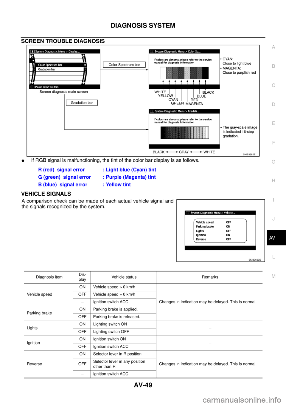
SCREEN TROUBLE DIAGNOSIS
lIf RGB signal is malfunctioning, the tint of the color bar display is as follows.
VEHICLE SIGNALS
Acomparisoncheckcanbemadeofeachactualvehiclesignaland
the signals recognized by the system.
SKIB3662E
R (red) signal error : Light blue (Cyan) tint
G (green) signal error : Purple (Magenta) tint
B (blue) signal error : Yellow tint
SKIB3663E
Diagnosis itemDis-
playVehicle status Remarks
Vehicle speedON Vehicle speed > 0 km/h
Changes in indication may be delayed. This is normal. OFF Vehicle speed = 0 km/h
– Ignition switch ACC
Parking brakeON Parking brake is applied.
OFF Parking brake is released.
LightsON Lighting switch ON
–
OFF Lighting switch OFF
IgnitionON Ignition switch ON
–
OFF Ignition switch ACC
ReverseON Selector lever in R position
Changes in indication may be delayed. This is normal. OFFSelector lever in any position
other than R
– Ignition switch ACC
Page 538 of 3171
AV-50
DIAGNOSIS SYSTEM
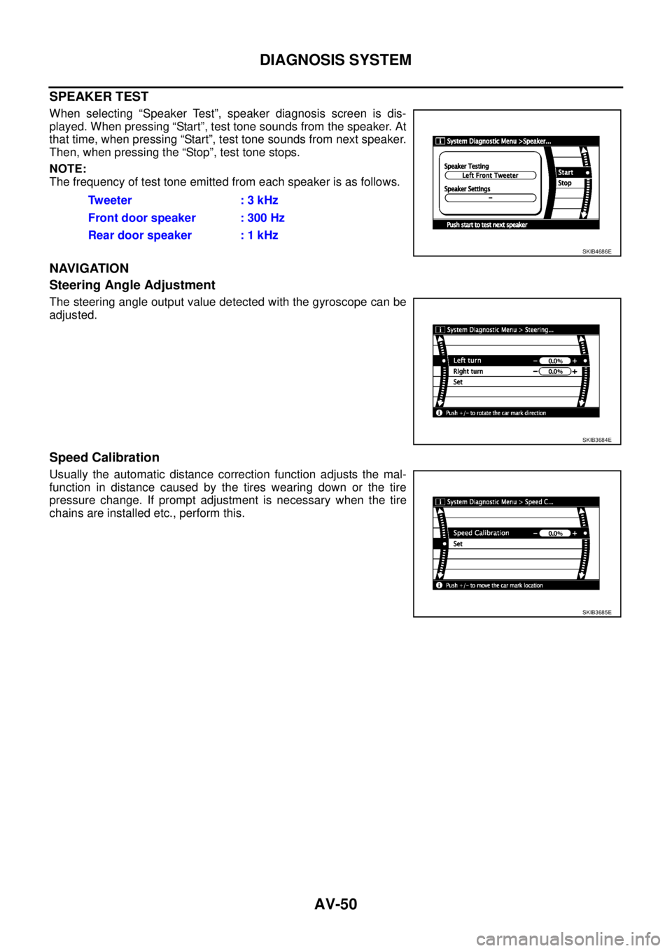
SPEAKER TEST
When selecting “Speaker Test”, speaker diagnosis screen is dis-
played. When pressing “Start”, test tone sounds from the speaker. At
that time, when pressing “Start”, test tone sounds from next speaker.
Then, when pressing the “Stop”, test tone stops.
NOTE:
The frequency of test tone emitted from each speaker is as follows.
NAVIGATION
Steering Angle Adjustment
The steering angle output value detected with the gyroscope can be
adjusted.
Speed Calibration
Usually the automatic distance correction function adjusts the mal-
function in distance caused by the tires wearing down or the tire
pressure change. If prompt adjustment is necessary when the tire
chains are installed etc., perform this.Tw e e t e r : 3 k H z
Front door speaker : 300 Hz
Rear door speaker : 1 kHz
SKIB4686E
SKIB3684E
SKIB3685E
Page 539 of 3171
DIAGNOSIS SYSTEM
AV-51
C
D
E
F
G
H
I
J
L
MA
B
AV
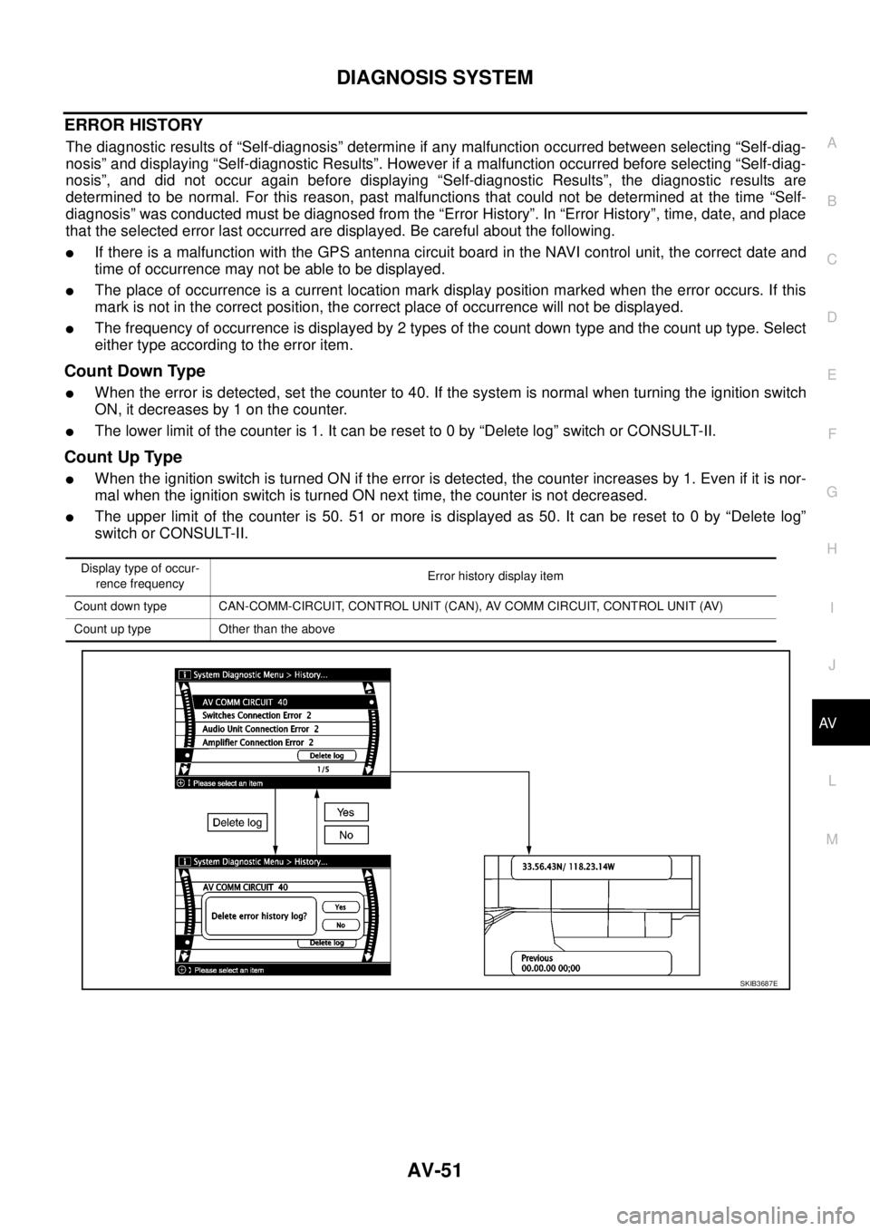
ERROR HISTORY
The diagnostic results of “Self-diagnosis” determine if any malfunction occurred between selecting “Self-diag-
nosis” and displaying “Self-diagnostic Results”. However if a malfunction occurred before selecting “Self-diag-
nosis”, and did not occur again before displaying “Self-diagnostic Results”, the diagnostic results are
determined to be normal. For this reason, past malfunctions that could not be determined at the time “Self-
diagnosis” was conducted must be diagnosed from the “Error History”. In “Error History”, time, date, and place
that the selected error last occurred are displayed. Be careful about the following.
lIf there is a malfunction with the GPS antenna circuit board in the NAVI control unit, the correct date and
time of occurrence may not be able to be displayed.
lThe place of occurrence is a current location mark display position marked when the error occurs. If this
mark is not in the correct position, the correct place of occurrence will not be displayed.
lThe frequency of occurrence is displayed by 2 types of the count down type and the count up type. Select
either type according to the error item.
Count Down Type
lWhen the error is detected, set the counter to 40. If the system is normal when turning the ignition switch
ON, it decreases by 1 on the counter.
lThe lower limit of the counter is 1. It can be reset to 0 by “Delete log” switch or CONSULT-II.
Count Up Type
lWhen the ignition switch is turned ON if the error is detected, the counter increases by 1. Even if it is nor-
mal when the ignition switch is turned ON next time, the counter is not decreased.
lThe upper limit of the counter is 50. 51 or more is displayed as 50. It can be reset to 0 by “Delete log”
switch or CONSULT-II.
Display type of occur-
rence frequencyError history display item
Count down type CAN-COMM-CIRCUIT, CONTROL UNIT (CAN), AV COMM CIRCUIT, CONTROL UNIT (AV)
Count up type Other than the above
SKIB3687E
Page 540 of 3171

AV-52
DIAGNOSIS SYSTEM
Error History Display Item
Some error items may be displayed simultaneously according to the cause. If some error items are displayed
simultaneously, the detection of the cause can be performed by the combination of display items
Display Item DescriptionPossible malfunction location/Action to
take
CAN_COMM_CIRCUITCAN communication malfunction is
detectedPerform the diagnosis using CONSULT-
II, and then repair the malfunctioning
parts by diagnostic results.
Refer toAV-47, "
DIAGNOSIS
RESULTS".
CONTROL UNIT (CAN)CAN initial diagnosis malfunction is
detectedReplace NAVI control unit
CONTROL UNIT (AV)AV communication circuit initial diagno-
sis malfunction is detectedReplace NAVI control unit
lCAN_COMM_CIRCUIT (AV)
lAudio Unit Connection Error
lAmplifier Connection Error
lRDS-TMC Error
lAudio unit power supply and ground
circuit malfunction is detected
lMalfunctionisdetectedoncommuni-
cation circuit between AV switch and
audio unit
lMalfunctionisdetectedoncommuni-
cation signal between audio unit and
NAVI control unit
lAudio unit power supply and ground
circuit
lCommunication circuit between AV
switch and audio unit
lAV switch
lAudio unit
lNAVI control unit
lCAN_COMM_CIRCUIT (AV)
lSwitches Connection Error
lAV switch power supply and ground
circuit malfunction is detected
lMalfunctioning is detected on com-
munication circuit AV switch and
NAVI control unit
lAV switch power supply and ground
circuit
lAV switch
lNAVI control unit
Front Display Connection Error
lDisplay unit power supply and ground
circuit malfunction is detected
lMalfunctionisdetectedoncommuni-
cation circuit between Display unit
and NAVI control unit
lMalfunctionisdetectedoncommuni-
cation signal between Display unit
and NAVI control unit
lDisplay unit power supply and ground
circuit
lCommunication circuit between Dis-
play unit and NAVI control unit
lDisplay unit
lNAVI control unit
GPS Antenna ErrorGPS antenna connection malfunction is
detected
lGPS antenna connection line condi-
tion
lGPS antenna
lGPS antenna feeder
lNAVI control unit
lCAN_COMM_CIRCUIT (AV)
lSwitches Connection Error
lAudio Unit Connection Error
lAmplifier Connection Error
lRDS-TMC Error
lMalfunctionisdetectedoncommuni-
cation circuit between NAVI control
unit and AV switch
lMalfunctionisdetectedoncommuni-
cation signal between NAVI control
unit and AV switch
lCommunication circuit between NAVI
control unit and AV switch
lNAVI control unit
lAV switch
FLASH-ROM Error Of Control Unit
NAVI control unit malfunction is
detectedReplace NAVI control unit
Connection Of Gyro
GPS Communication Error
GPS malfunction is detectedIf the symptom such as the GPS receiv-
ing malfunction occurs, intermittent mal-
function caused by strong radio
interference may be detected. If the
malfunction always occurs, replace
NAVI control unit. GPS ROM Error
GPS RAM Error
GPS RTC Error