NISSAN NAVARA 2005 Repair Workshop Manual
Manufacturer: NISSAN, Model Year: 2005, Model line: NAVARA, Model: NISSAN NAVARA 2005Pages: 3171, PDF Size: 49.59 MB
Page 541 of 3171
DIAGNOSIS SYSTEM
AV-53
C
D
E
F
G
H
I
J
L
MA
B
AV
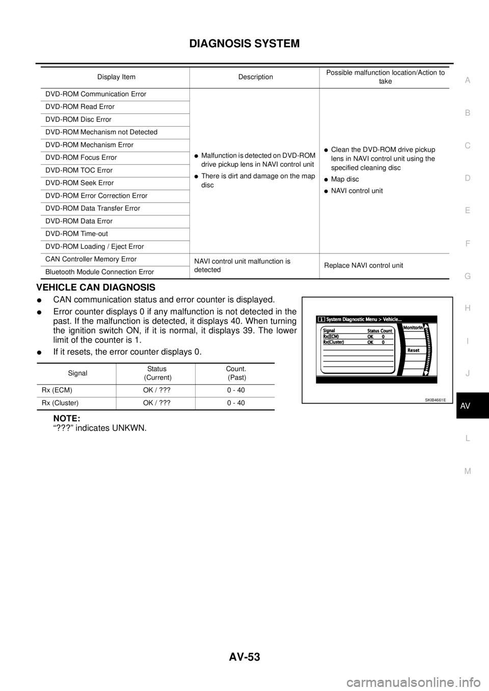
VEHICLE CAN DIAGNOSIS
lCAN communication status and error counter is displayed.
lError counter displays 0 if any malfunction is not detected in the
past. If the malfunction is detected, it displays 40. When turning
the ignition switch ON, if it is normal, it displays 39. The lower
limitofthecounteris1.
lIf it resets, the error counter displays 0.
NOTE:
“???” indicates UNKWN.
DVD-ROM Communication Error
lMalfunction is detected on DVD-ROM
drive pickup lens in NAVI control unit
lThere is dirt and damage on the map
disc
lClean the DVD-ROM drive pickup
lens in NAVI control unit using the
specified cleaning disc
lMap disc
lNAVI control unit DVD-ROM Read Error
DVD-ROM Disc Error
DVD-ROM Mechanism not Detected
DVD-ROM Mechanism Error
DVD-ROM Focus Error
DVD-ROM TOC Error
DVD-ROM Seek Error
DVD-ROM Error Correction Error
DVD-ROM Data Transfer Error
DVD-ROM Data Error
DVD-ROM Time-out
DVD-ROM Loading / Eject Error
CAN Controller Memory Error
NAVI control unit malfunction is
detectedReplace NAVI control unit
Bluetooth Module Connection ErrorDisplay Item DescriptionPossible malfunction location/Action to
take
SignalStatu s
(Current)Count.
(Past)
Rx (ECM) OK / ??? 0 - 40
Rx (Cluster) OK / ??? 0 - 40
SKIB4661E
Page 542 of 3171
AV-54
DIAGNOSIS SYSTEM
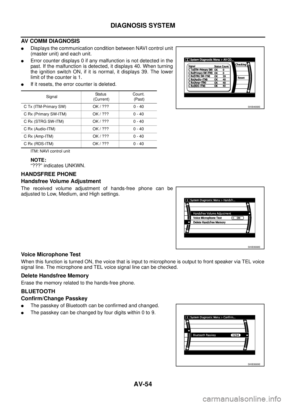
AV COMM DIAGNOSIS
lDisplays the communication condition between NAVI control unit
(master unit) and each unit.
lError counter displays 0 if any malfunction is not detected in the
past. If the malfunction is detected, it displays 40. When turning
the ignition switch ON, if it is normal, it displays 39. The lower
limitofthecounteris1.
lIf it resets, the error counter is deleted.
ITM: NAVI control unit
NOTE:
“???” indicates UNKWN.
HANDSFREE PHONE
Handsfree Volume Adjustment
The received volume adjustment of hands-free phone can be
adjusted to Low, Medium, and High settings.
Voice Microphone Test
When this function is turned ON, the voice that is input to microphone is output to front speaker via TEL voice
signal line. The microphone and TEL voice signal line can be checked.
Delete Handsfree Memory
Erase the memory related to the hands-free phone.
BLUETOOTH
Confirm/Change Passkey
lThe passkey of Bluetooth can be confirmed and changed.
lThe passkey can be changed by four digits within 0 to 9.
SignalStatus
(Current)Count.
(Past)
C Tx (ITM-Primary SW) OK / ??? 0 - 40
CRx(PrimarySW-ITM) OK/??? 0-40
C Rx (STRG SW-ITM) OK / ??? 0 - 40
C Rx (Audio-ITM) OK / ??? 0 - 40
C Rx (Amp-ITM) OK / ??? 0 - 40
C Rx (RDS-ITM) OK / ??? 0 - 40
SKIB4668E
SKIB3668E
SKIB3669E
Page 543 of 3171
DIAGNOSIS SYSTEM
AV-55
C
D
E
F
G
H
I
J
L
MA
B
AV
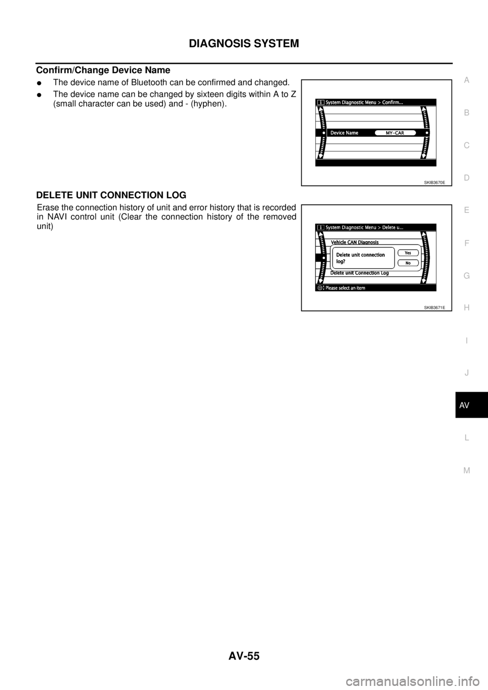
Confirm/Change Device Name
lThe device name of Bluetooth can be confirmed and changed.
lThe device name can be changed by sixteen digits within A to Z
(small character can be used) and - (hyphen).
DELETE UNIT CONNECTION LOG
Erase the connection history of unit and error history that is recorded
in NAVI control unit (Clear the connection history of the removed
unit)
SKIB3670E
SKIB3671E
Page 544 of 3171
AV-56
DIAGNOSIS SYSTEM
CONSULT-II Functions
EKS00Q6L
CONSULT-II FUNCTIONS
CONSULT-II can display each diagnostic item using the diagnostic test modes shown following.
CONSULT-II BASIC OPERATION PROCEDURE
CAUTION:
If CONSULT-II is used with no connection of CONSULT-II CONVERTER, malfunctions might be
detected in self-diagnosis depending on control unit which carry out CAN communication.
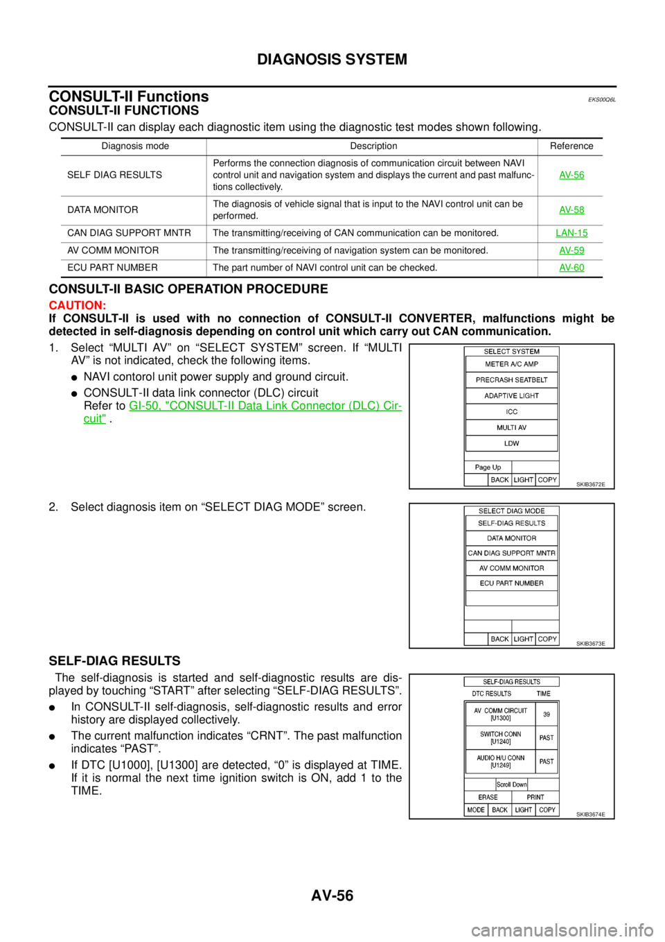
1. Select “MULTI AV” on “SELECT SYSTEM” screen. If “MULTI
AV” is not indicated, check the following items.
lNAVI contorol unit power supply and ground circuit.
lCONSULT-II data link connector (DLC) circuit
Refer toGI-50, "
CONSULT-II Data Link Connector (DLC) Cir-
cuit".
2. Select diagnosis item on “SELECT DIAG MODE” screen.
SELF-DIAG RESULTS
The self-diagnosis is started and self-diagnostic results are dis-
played by touching “START” after selecting “SELF-DIAG RESULTS”.
lIn CONSULT-II self-diagnosis, self-diagnostic results and error
history are displayed collectively.
lThe current malfunction indicates “CRNT”. The past malfunction
indicates “PAST”.
lIf DTC [U1000], [U1300] are detected, “0” is displayed at TIME.
If it is normal the next time ignition switch is ON, add 1 to the
TIME.
Diagnosis mode Description Reference
SELF DIAG RESULTSPerforms the connection diagnosis of communication circuit between NAVI
control unit and navigation system and displays the current and past malfunc-
tions collectively.AV- 5 6
DATA MONITORThe diagnosis of vehicle signal that is input to the NAVI control unit can be
performed.AV- 5 8
CAN DIAG SUPPORT MNTR The transmitting/receiving of CAN communication can be monitored.LAN-15
AV COMM MONITOR The transmitting/receiving of navigation system can be monitored.AV- 5 9
ECU PART NUMBER The part number of NAVI control unit can be checked.AV- 6 0
SKIB3672E
SKIB3673E
SKIB3674E
Page 545 of 3171
DIAGNOSIS SYSTEM
AV-57
C
D
E
F
G
H
I
J
L
MA
B
AV
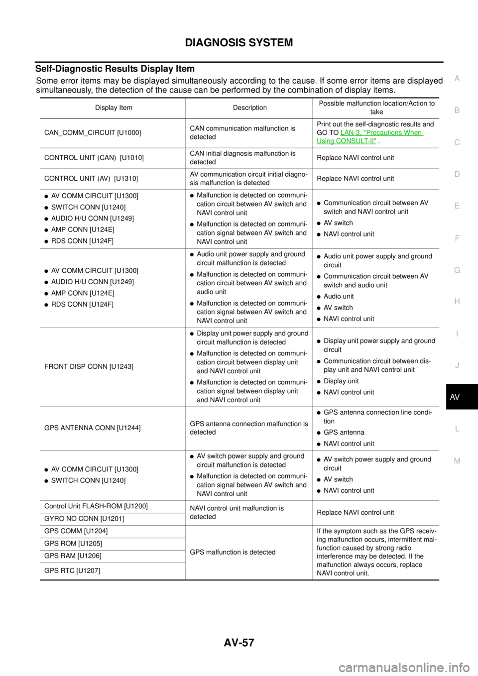
Self-Diagnostic Results Display Item
Some error items may be displayed simultaneously according to the cause. If some error items are displayed
simultaneously, the detection of the cause can be performed by the combination of display items.
Display Item DescriptionPossible malfunction location/Action to
take
CAN_COMM_CIRCUIT [U1000]CAN communication malfunction is
detectedPrint out the self-diagnostic results and
GO TOLAN-3, "
Precautions When
Using CONSULT-II".
CONTROL UNIT (CAN) [U1010]CAN initial diagnosis malfunction is
detectedReplace NAVI control unit
CONTROL UNIT (AV) [U1310]AV communication circuit initial diagno-
sis malfunction is detectedReplace NAVI control unit
lAV COMM CIRCUIT [U1300]
lSWITCH CONN [U1240]
lAUDIO H/U CONN [U1249]
lAMP CONN [U124E]
lRDS CONN [U124F]
lMalfunction is detected on communi-
cation circuit between AV switch and
NAVI control unit
lMalfunction is detected on communi-
cation signal between AV switch and
NAVI control unit
lCommunication circuit between AV
switch and NAVI control unit
lAV switch
lNAVI control unit
lAV COMM CIRCUIT [U1300]
lAUDIO H/U CONN [U1249]
lAMP CONN [U124E]
lRDS CONN [U124F]
lAudio unit power supply and ground
circuit malfunction is detected
lMalfunction is detected on communi-
cation circuit between AV switch and
audio unit
lMalfunction is detected on communi-
cation signal between AV switch and
NAVI control unit
lAudio unit power supply and ground
circuit
lCommunication circuit between AV
switch and audio unit
lAudio unit
lAV switch
lNAVI control unit
FRONT DISP CONN [U1243]
lDisplay unit power supply and ground
circuit malfunction is detected
lMalfunction is detected on communi-
cation circuit between display unit
and NAVI control unit
lMalfunction is detected on communi-
cation signal between display unit
and NAVI control unit
lDisplay unit power supply and ground
circuit
lCommunication circuit between dis-
play unit and NAVI control unit
lDisplay unit
lNAVI control unit
GPS ANTENNA CONN [U1244]GPS antenna connection malfunction is
detected
lGPS antenna connection line condi-
tion
lGPS antenna
lNAVI control unit
lAV COMM CIRCUIT [U1300]
lSWITCH CONN [U1240]
lAV switch power supply and ground
circuit malfunction is detected
lMalfunction is detected on communi-
cation signal between AV switch and
NAVI control unit
lAV switch power supply and ground
circuit
lAV switch
lNAVI control unit
Control Unit FLASH-ROM [U1200]
NAVI control unit malfunction is
detectedReplace NAVI control unit
GYRO NO CONN [U1201]
GPS COMM [U1204]
GPS malfunction is detectedIf the symptom such as the GPS receiv-
ing malfunction occurs, intermittent mal-
function caused by strong radio
interference may be detected. If the
malfunction always occurs, replace
NAVI control unit. GPS ROM [U1205]
GPS RAM [U1206]
GPS RTC [U1207]
Page 546 of 3171
AV-58
DIAGNOSIS SYSTEM
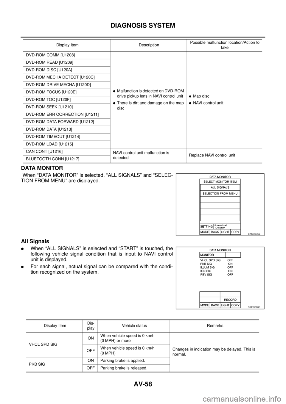
DATA MONITOR
When “DATA MONITOR” is selected, “ALL SIGNALS” and “SELEC-
TION FROM MENU” are displayed.
All Signals
lWhen “ALL SIGNALS” is selected and “START” is touched, the
following vehicle signal condition that is input to NAVI control
unit is displayed.
lFor each signal, actual signal can be compared with the condi-
tion recognized on the system.
DVD-ROM COMM [U1208]
lMalfunctionisdetectedonDVD-ROM
drive pickup lens in NAVI control unit
lThere is dirt and damage on the map
disc
lMap disc
lNAVI control unit DVD-ROM READ [U1209]
DVD-ROM DISC [U120A]
DVD-ROM MECHA DETECT [U120C]
DVD-ROM DRIVE MECHA [U120D]
DVD-ROM FOCUS [U120E]
DVD-ROM TOC [U120F]
DVD-ROM SEEK [U1210]
DVD-ROM ERR CORRECTION [U1211]
DVD-ROM DATA FORWARD [U1212]
DVD-ROM DATA [U1213]
DVD-ROM TIMEOUT [U1214]
DVD-ROM LOAD [U1215]
CAN CONT [U1216]
NAVI control unit malfunction is
detectedReplace NAVI control unit
BLUETOOTH CONN [U1217]Display Item DescriptionPossible malfunction location/Action to
take
SKIB3675E
SKIB3676E
Display ItemDis-
playVehicle status Remarks
VHCL SPD SIGONWhen vehicle speed is 0 km/h
(0 MPH) or more
Changes in indication may be delayed. This is
normal. OFFWhen vehicle speed is 0 km/h
(0 MPH)
PKB SIGON Parking brake is applied.
OFF Parking brake is released.
Page 547 of 3171
DIAGNOSIS SYSTEM
AV-59
C
D
E
F
G
H
I
J
L
MA
B
AV
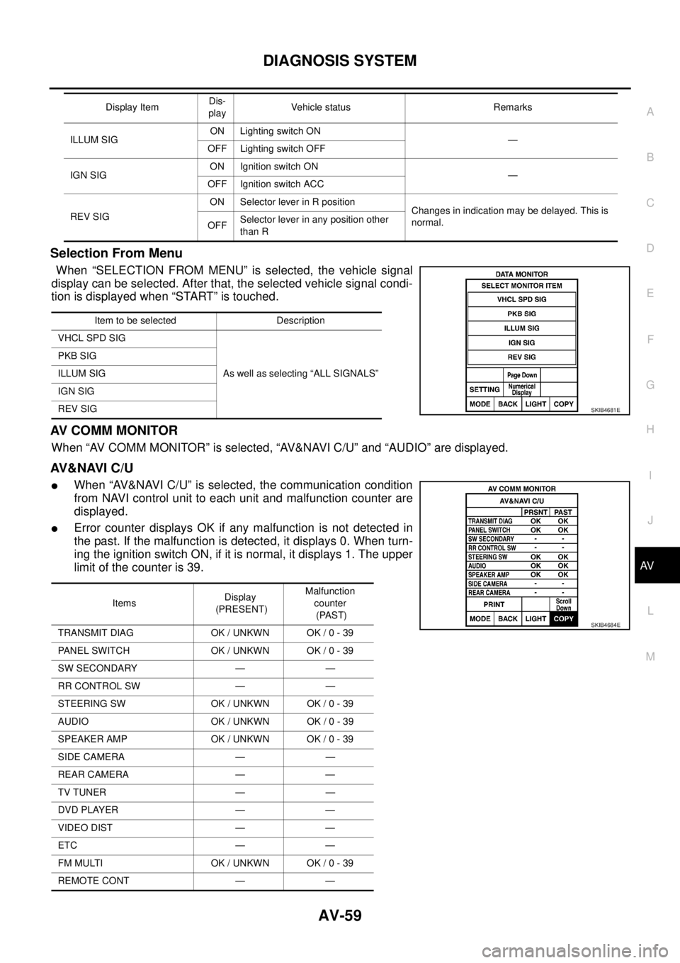
Selection From Menu
When “SELECTION FROM MENU” is selected, the vehicle signal
display can be selected. After that, the selected vehicle signal condi-
tion is displayed when “START” is touched.
AV C O M M M O N I T O R
When “AV COMM MONITOR” is selected, “AV&NAVI C/U” and “AUDIO” are displayed.
AV&NAVI C/U
lWhen “AV&NAVI C/U” is selected, the communication condition
from NAVI control unit to each unit and malfunction counter are
displayed.
lError counter displays OK if any malfunction is not detected in
the past. If the malfunction is detected, it displays 0. When turn-
ing the ignition switch ON, if it is normal, it displays 1. The upper
limitofthecounteris39.
ILLUM SIGON Lighting switch ON
—
OFF Lighting switch OFF
IGN SIGON Ignition switch ON
—
OFF Ignition switch ACC
REV SIGON Selector lever in R position
Changes in indication may be delayed. This is
normal.
OFFSelector lever in any position other
than R Display ItemDis-
playVehicle status Remarks
Item to be selected Description
VHCL SPD SIG
As well as selecting “ALL SIGNALS” PKB SIG
ILLUM SIG
IGN SIG
REV SIG
SKIB4681E
ItemsDisplay
(PRESENT)Malfunction
counter
(PAST)
TRANSMIT DIAG OK / UNKWN OK / 0 - 39
PANEL SWITCH OK / UNKWN OK / 0 - 39
SW SECONDARY — —
RR CONTROL SW — —
STEERING SW OK / UNKWN OK / 0 - 39
AUDIO OK / UNKWN OK / 0 - 39
SPEAKER AMP OK / UNKWN OK / 0 - 39
SIDE CAMERA — —
REAR CAMERA — —
TV TUNER — —
DVD PLAYER — —
VIDEO DIST — —
ETC — —
FM MULTI OK / UNKWN OK / 0 - 39
REMOTE CONT — —
SKIB4684E
Page 548 of 3171
AV-60
DIAGNOSIS SYSTEM
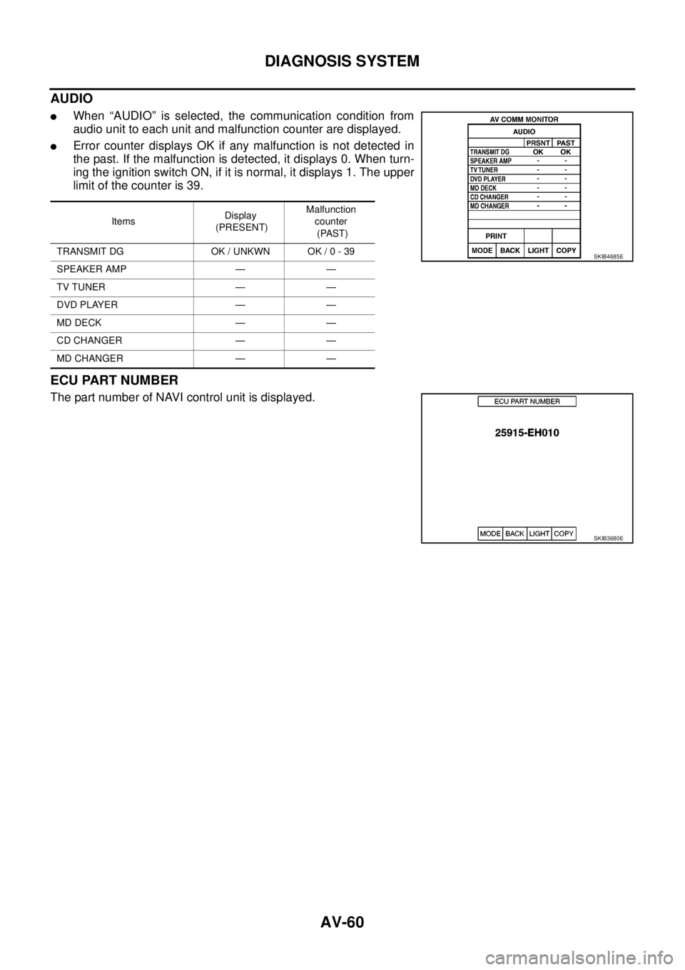
AUDIO
lWhen “AUDIO” is selected, the communication condition from
audio unit to each unit and malfunction counter are displayed.
lError counter displays OK if any malfunction is not detected in
the past. If the malfunction is detected, it displays 0. When turn-
ing the ignition switch ON, if it is normal, it displays 1. The upper
limitofthecounteris39.
ECU PART NUMBER
The part number of NAVI control unit is displayed.
ItemsDisplay
(PRESENT)Malfunction
counter
(PAST)
TRANSMIT DG OK / UNKWN OK / 0 - 39
SPEAKER AMP — —
TV TUNER — —
DVD PLAYER — —
MD DECK — —
CD CHANGER — —
MD CHANGER — —
SKIB4685E
SKIB3680E
Page 549 of 3171
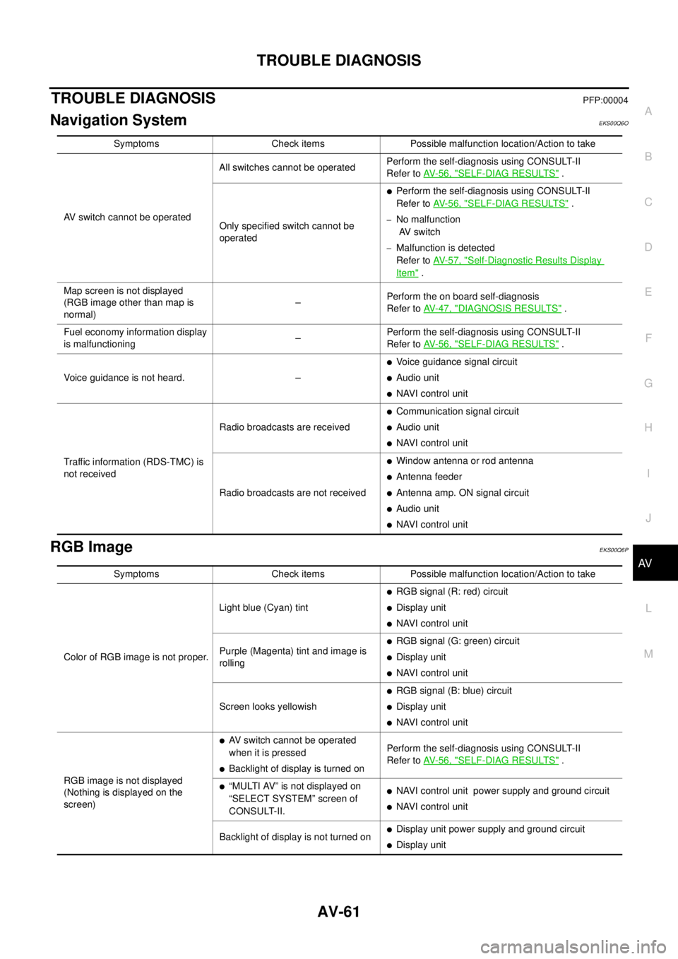
TROUBLE DIAGNOSIS
AV-61
C
D
E
F
G
H
I
J
L
MA
B
AV
TROUBLE DIAGNOSISPFP:00004
Navigation SystemEKS00Q6O
RGB ImageEKS00Q6P
Symptoms Check items Possible malfunction location/Action to take
AV switch cannot be operatedAll switches cannot be operatedPerform the self-diagnosis using CONSULT-II
Refer toAV-56, "
SELF-DIAG RESULTS".
Only specified switch cannot be
operated
lPerform the self-diagnosis using CONSULT-II
Refer toAV-56, "
SELF-DIAG RESULTS".
–No malfunction
AV switch
–Malfunction is detected
Refer toAV-57, "
Self-Diagnostic Results Display
Item".
Map screen is not displayed
(RGB image other than map is
normal)–Perform the on board self-diagnosis
Refer toAV-47, "
DIAGNOSIS RESULTS".
Fuel economy information display
is malfunctioning–Perform the self-diagnosis using CONSULT-II
Refer toAV-56, "
SELF-DIAG RESULTS".
Voice guidance is not heard. –
lVoice guidance signal circuit
lAudio unit
lNAVI control unit
Traffic information (RDS-TMC) is
not receivedRadio broadcasts are received
lCommunication signal circuit
lAudio unit
lNAVI control unit
Radio broadcasts are not received
lWindow antenna or rod antenna
lAntenna feeder
lAntenna amp. ON signal circuit
lAudio unit
lNAVI control unit
Symptoms Check items Possible malfunction location/Action to take
Color of RGB image is not proper.Light blue (Cyan) tint
lRGB signal (R: red) circuit
lDisplay unit
lNAVI control unit
Purple (Magenta) tint and image is
rolling
lRGB signal (G: green) circuit
lDisplay unit
lNAVI control unit
Screen looks yellowish
lRGB signal (B: blue) circuit
lDisplay unit
lNAVI control unit
RGB image is not displayed
(Nothing is displayed on the
screen)
lAV switch cannot be operated
when it is pressed
lBacklight of display is turned onPerform the self-diagnosis using CONSULT-II
Refer toAV-56, "SELF-DIAG RESULTS".
l“MULTI AV” is not displayed on
“SELECT SYSTEM” screen of
CONSULT-II.lNAVI control unit power supply and ground circuit
lNAVI control unit
Backlight of display is not turned on
lDisplay unit power supply and ground circuit
lDisplay unit
Page 550 of 3171

AV-62
TROUBLE DIAGNOSIS
Voice Activated Control System
EKS00Q6Q
Symptoms Check items Probable malfunction location
The voice cannot be controlled
even if the voice control screen is
displayedVoice sounds at “Speaker Test” and
“Voice Microphone Test” of Confir-
mation/Adjustment modeNAVI control unit
Voice does not sound at “Speaker
Test” and “Voice Microphone Test” of
Confirmation/Adjustment mode
lMIC. power supply circuit
lShield (MIC.) circuit
lMIC. signal circuit
lMicrophone
lNAVI control unit
The voice cannot be controlled
(Voice control screen is not dis-
played)TEL operation screen is displayed by
pressing and holding “TEL/PPT”
switch of steering wheel switchNAVI control unit
lTEL operation screen is not dis-
played by pressing and holding
“TEL/PPT” switch of steering
wheel switch
lOther steering wheel switches are
normalSteering wheel switch
“BACK”, “VOL UP”, “VOL DOWN”,
and “TEL/PPT” switches of steering
wheel switch are not operated
lRemote control signal B circuit
lSteering wheel switch
lAudio unit
All steering wheel switches are not
operated
lRemote control signal ground circuit
lSteering wheel switch
lAudio unit