NISSAN NAVARA 2005 Repair Workshop Manual
Manufacturer: NISSAN, Model Year: 2005, Model line: NAVARA, Model: NISSAN NAVARA 2005Pages: 3171, PDF Size: 49.59 MB
Page 921 of 3171
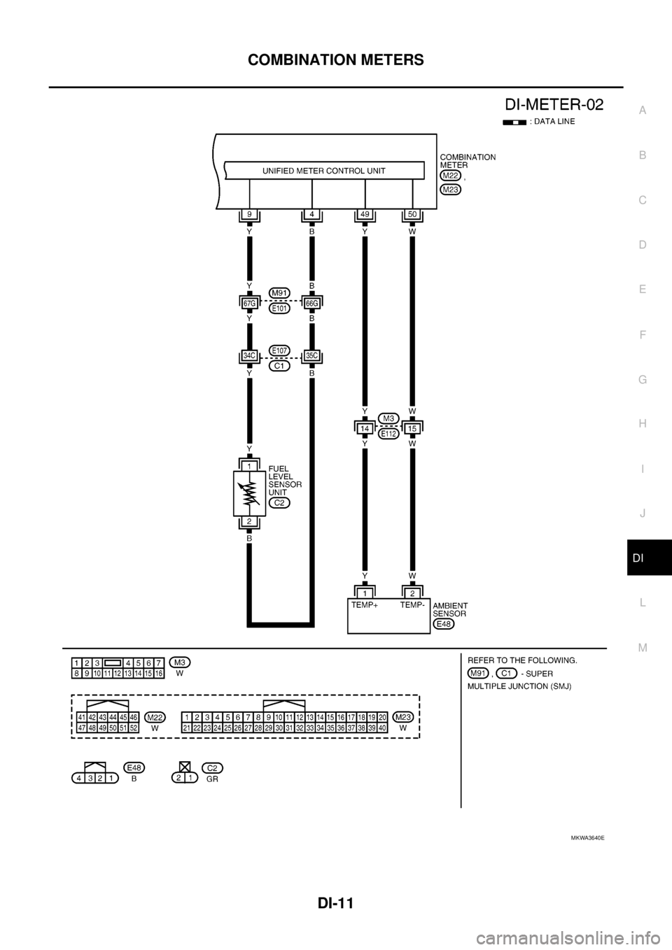
COMBINATION METERS
DI-11
C
D
E
F
G
H
I
J
L
MA
B
DI
MKWA3640E
Page 922 of 3171
DI-12
COMBINATION METERS
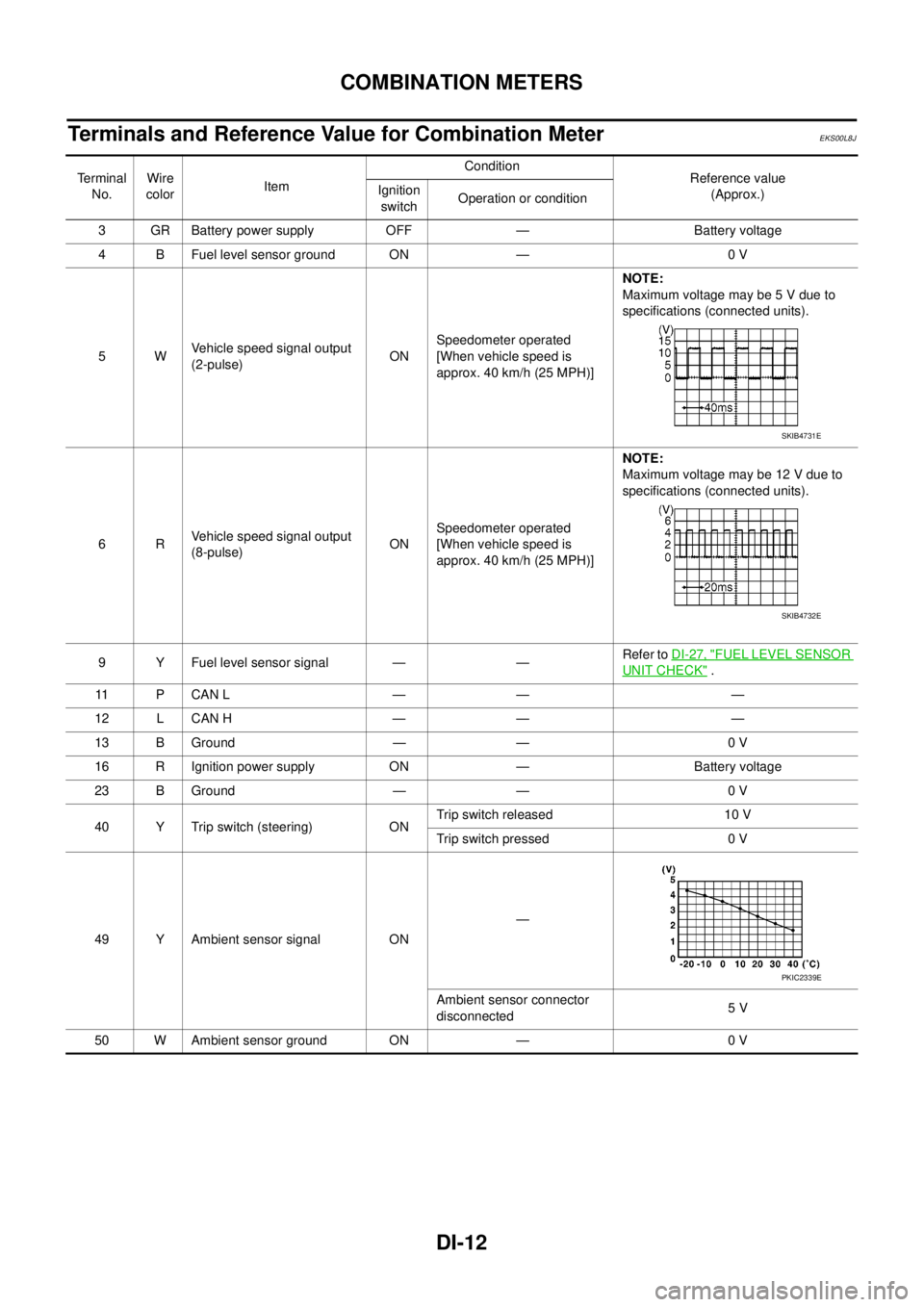
Terminals and Reference Value for Combination Meter
EKS00L8J
Te r m i n a l
No.Wire
colorItemCondition
Reference value
(Approx.) Ignition
switchOperation or condition
3 GR Battery power supply OFF — Battery voltage
4 B Fuel level sensor ground ON — 0 V
5WVehicle speed signal output
(2-pulse)ONSpeedometer operated
[When vehicle speed is
approx. 40 km/h (25 MPH)]NOTE:
Maximum voltage may be 5 V due to
specifications (connected units).
6RVehicle speed signal output
(8-pulse)ONSpeedometer operated
[When vehicle speed is
approx. 40 km/h (25 MPH)]NOTE:
Maximum voltage may be 12 V due to
specifications (connected units).
9 Y Fuel level sensor signal — —Refer toDI-27, "
FUEL LEVEL SENSOR
UNIT CHECK".
11 P C A N L — — —
12 L CAN H — — —
13 B Ground — — 0 V
16 R Ignition power supply ON — Battery voltage
23 B Ground — — 0 V
40 Y Trip switch (steering) ONTrip switch released 10 V
Trip switch pressed 0 V
49 Y Ambient sensor signal ON—
Ambient sensor connector
disconnected5V
50 W Ambient sensor ground ON — 0 V
SKIB4731E
SKIB4732E
PKIC2339E
Page 923 of 3171
COMBINATION METERS
DI-13
C
D
E
F
G
H
I
J
L
MA
B
DI
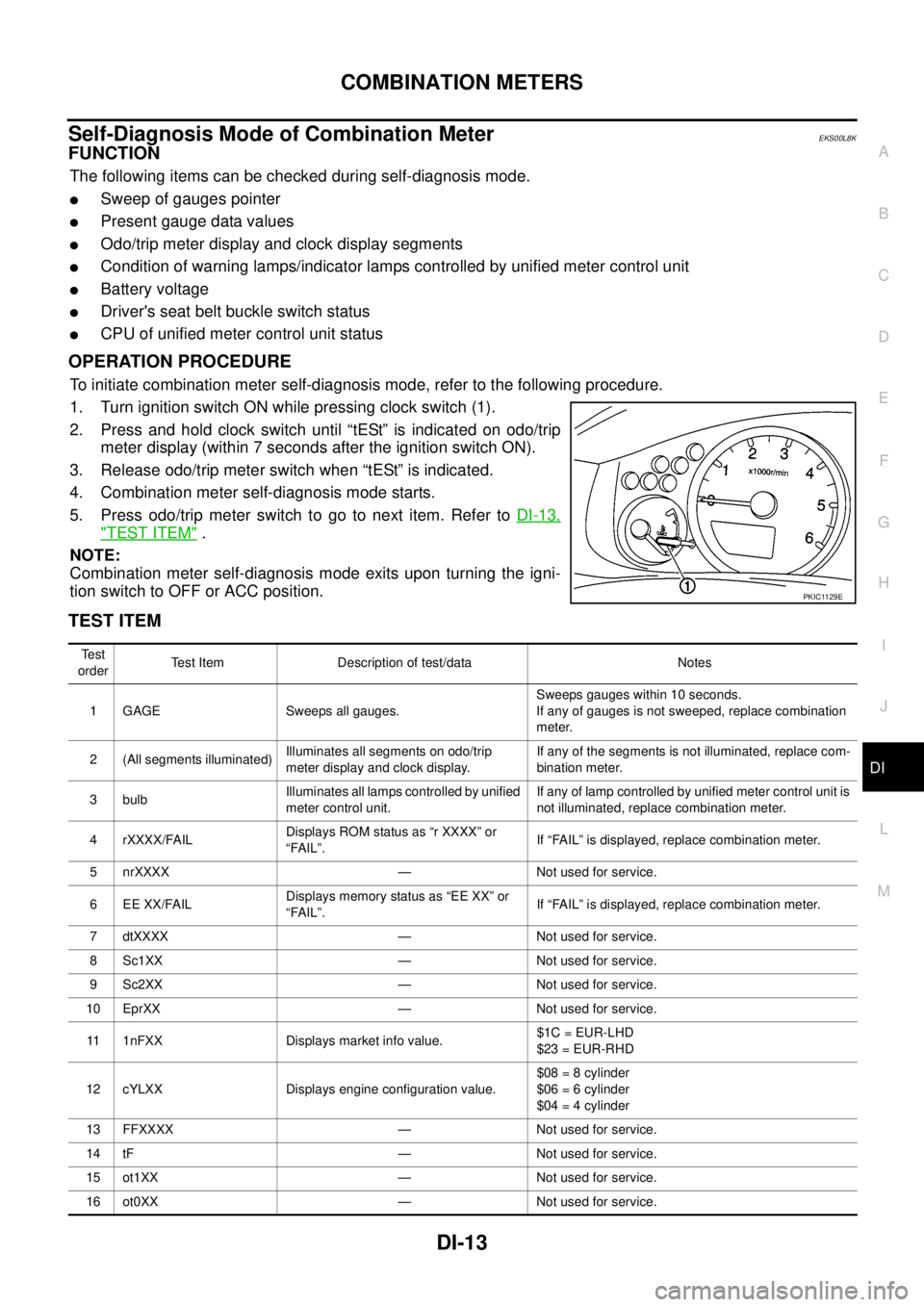
Self-Diagnosis Mode of Combination MeterEKS00L8K
FUNCTION
The following items can be checked during self-diagnosis mode.
lSweep of gauges pointer
lPresent gauge data values
lOdo/trip meter display and clock display segments
lCondition of warning lamps/indicator lamps controlled by unified meter control unit
lBattery voltage
lDriver's seat belt buckle switch status
lCPU of unified meter control unit status
OPERATION PROCEDURE
To initiate combination meter self-diagnosis mode, refer to the following procedure.
1. Turn ignition switch ON while pressing clock switch (1).
2. Press and hold clock switch until “tESt” is indicated on odo/trip
meter display (within 7 seconds after the ignition switch ON).
3. Release odo/trip meter switch when “tESt” is indicated.
4. Combination meter self-diagnosis mode starts.
5. Pressodo/tripmeterswitchtogotonextitem.RefertoDI-13,
"TEST ITEM".
NOTE:
Combination meter self-diagnosis mode exits upon turning the igni-
tion switch to OFF or ACC position.
TEST ITEM
PKIC1129E
Te s t
orderTest Item Description of test/data Notes
1 GAGE Sweeps all gauges.Sweeps gauges within 10 seconds.
If any of gauges is not sweeped, replace combination
meter.
2 (All segments illuminated)Illuminates all segments on odo/trip
meter display and clock display.If any of the segments is not illuminated, replace com-
bination meter.
3 bulbIlluminates all lamps controlled by unified
meter control unit.If any of lamp controlled by unified meter control unit is
not illuminated, replace combination meter.
4 rXXXX/FAILDisplays ROM status as “r XXXX” or
“FAIL”.If “FAIL” is displayed, replace combination meter.
5 nrXXXX — Not used for service.
6 EE XX/FAILDisplays memory status as “EE XX” or
“FAIL”.If “FAIL” is displayed, replace combination meter.
7 dtXXXX — Not used for service.
8 Sc1XX — Not used for service.
9 Sc2XX — Not used for service.
10 EprXX — Not used for service.
11 1nFXX Displays market info value.$1C = EUR-LHD
$23 = EUR-RHD
12 cYLXX Displays engine configuration value.$08 = 8 cylinder
$06 = 6 cylinder
$04 = 4 cylinder
13 FFXXXX — Not used for service.
14 tF — Not used for service.
15 ot1XX — Not used for service.
16 ot0XX — Not used for service.
Page 924 of 3171

DI-14
COMBINATION METERS
17 XXXXXDisplays vehicle speed signal value
(MPH).Displays “-----” if message is not received.
Displays “99999” if data received is invalid.
If “-----” or “99999” is displayed, performDI-20, "Ve h i-
cle Speed Signal Inspection".
18 XXXXXDisplays vehicle speed signal value
(km/h).Displays “-----” if message is not received.
Displays “99999” if data received is invalid.
If “-----” or “99999” is displayed, performDI-20, "
Ve h i-
cle Speed Signal Inspection".
19 tXXXXDisplays engine speed signal value
(RPM).Displays “-----” if message is not received.
If “-----” is displayed, performDI-21, "
Engine Speed
Signal Inspection".
20 F1 XXXXDisplays ratioed fuel level sensor signal
value.000-009 = Short circuit
010-254 = Normal range
255 = Open circuit
--- = Missing 5 seconds
If “000-009” or “255” is displayed, performDI-22, "
Fuel
Level Sensor Signal Inspection".
21 XXXCDisplays engine coolant temperature sig-
nal value (°C).Displays “---” C if message is not received.
Displays “999” C if data received is invalid.
If “---” or “999” is displayed, performDI-21, "
Engine
Coolant Temperature Signal Inspection".
22 BAt XXX Displays battery voltage.
23 rES -X Driver's seat belt buckle switch status.1= Buckled
0 = Unbuckled
24 PA -XX — Not used for service.
25 Pb -XX — Not used for service.
26 PE -XX — Not used for service.
27 PL -XX — Not used for service.
28 P6 -XX — Not used for service.
29 Pn -XX — Not used for service.
30 PP -XX — Not used for service.
31 PS -XX — Not used for service.
32 Pt -XX — Not used for service.
33 Pu -XX — Not used for service.
34 P4 -XX — Not used for service.
35 Puu -XX — Not used for service.
36 A00XXX — Not used for service.
37 A01XXX — Not used for service.
38 A02XXX — Not used for service.
39 A03XXX — Not used for service.
40 A04XXX — Not used for service.
41 A05XXX — Not used for service.
42 A06XXX — Not used for service.
43 A07XXX — Not used for service.
44 A08XXX — Not used for service.
45 A09XXX — Not used for service.
46 A10XXX — Not used for service.
47 A11XXX — Not used for service.
48 A12XXX — Not used for service. Te s t
orderTest Item Description of test/data Notes
Page 925 of 3171
COMBINATION METERS
DI-15
C
D
E
F
G
H
I
J
L
MA
B
DI
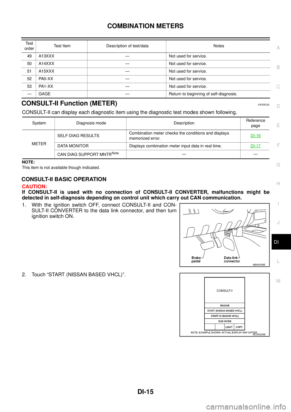
CONSULT-II Function (METER)EKS00L8L
CONSULT-II can display each diagnostic item using the diagnostic test modes shown following.
NOTE:
This item is not available though indicated.
CONSULT-II BASIC OPERATION
CAUTION:
If CONSULT-II is used with no connection of CONSULT-II CONVERTER, malfunctions might be
detected in self-diagnosis depending on control unit which carry out CAN communication.
1. With the ignition switch OFF, connect CONSULT-II and CON-
SULT-II CONVERTER to the data link connector, and then turn
ignition switch ON.
2. Touch “START (NISSAN BASED VHCL)”.
49 A13XXX — Not used for service.
50 A14XXX — Not used for service.
51 A15XXX — Not used for service.
52 PA0-XX — Not used for service.
53 PA1-XX — Not used for service.
— GAGE — Return to beginning of self-diagnosis. Te s t
orderTest Item Description of test/data Notes
System Diagnosis mode DescriptionReference
page
METERSELF-DIAG RESULTSCombination meter checks the conditions and displays
memorized error.DI-16
DATA MONITOR Displays combination meter input data in real time.DI-17
CAN DIAG SUPPORT MNTRNote——
BBIA0538E
BCIA0029E
Page 926 of 3171
DI-16
COMBINATION METERS
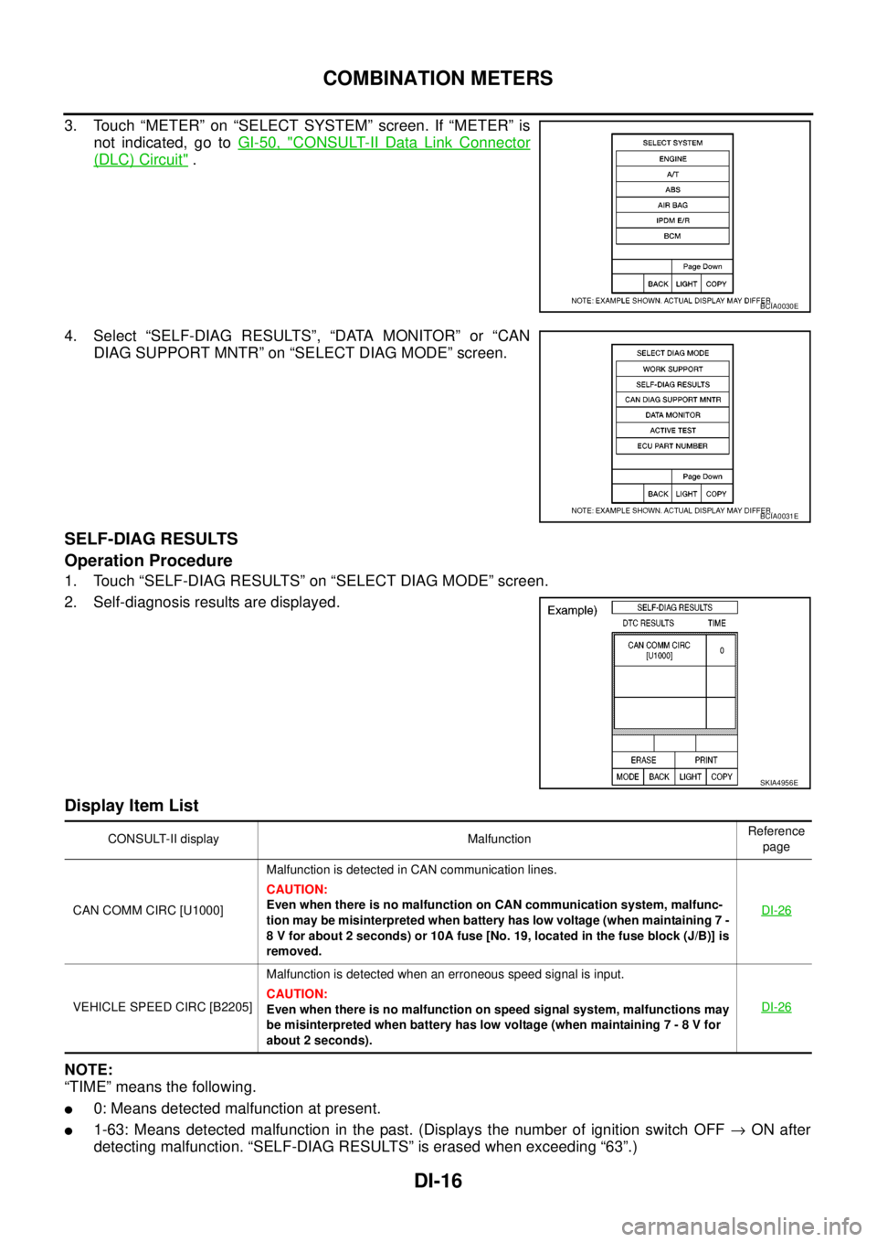
3. Touch “METER” on “SELECT SYSTEM” screen. If “METER” is
not indicated, go toGI-50, "
CONSULT-II Data Link Connector
(DLC) Circuit".
4. Select “SELF-DIAG RESULTS”, “DATA MONITOR” or “CAN
DIAG SUPPORT MNTR” on “SELECT DIAG MODE” screen.
SELF-DIAG RESULTS
Operation Procedure
1. Touch “SELF-DIAG RESULTS” on “SELECT DIAG MODE” screen.
2. Self-diagnosis results are displayed.
Display Item List
NOTE:
“TIME” means the following.
l0: Means detected malfunction at present.
l1-63: Means detected malfunction in the past. (Displays the number of ignition switch OFF®ON after
detecting malfunction. “SELF-DIAG RESULTS” is erased when exceeding “63”.)
BCIA0030E
BCIA0031E
SKIA4956E
CONSULT-II display MalfunctionReference
page
CAN COMM CIRC [U1000]Malfunction is detected in CAN communication lines.
CAUTION:
Even when there is no malfunction on CAN communication system, malfunc-
tion may be misinterpreted when battery has low voltage (when maintaining 7 -
8 V for about 2 seconds) or 10A fuse [No. 19, located in the fuse block (J/B)] is
removed.DI-26
VEHICLE SPEED CIRC [B2205]Malfunction is detected when an erroneous speed signal is input.
CAUTION:
Even when there is no malfunction on speed signal system, malfunctions may
be misinterpreted when battery has low voltage (when maintaining 7 - 8 V for
about 2 seconds).DI-26
Page 927 of 3171
COMBINATION METERS
DI-17
C
D
E
F
G
H
I
J
L
MA
B
DI
DATA MONITOR
Operation Procedure
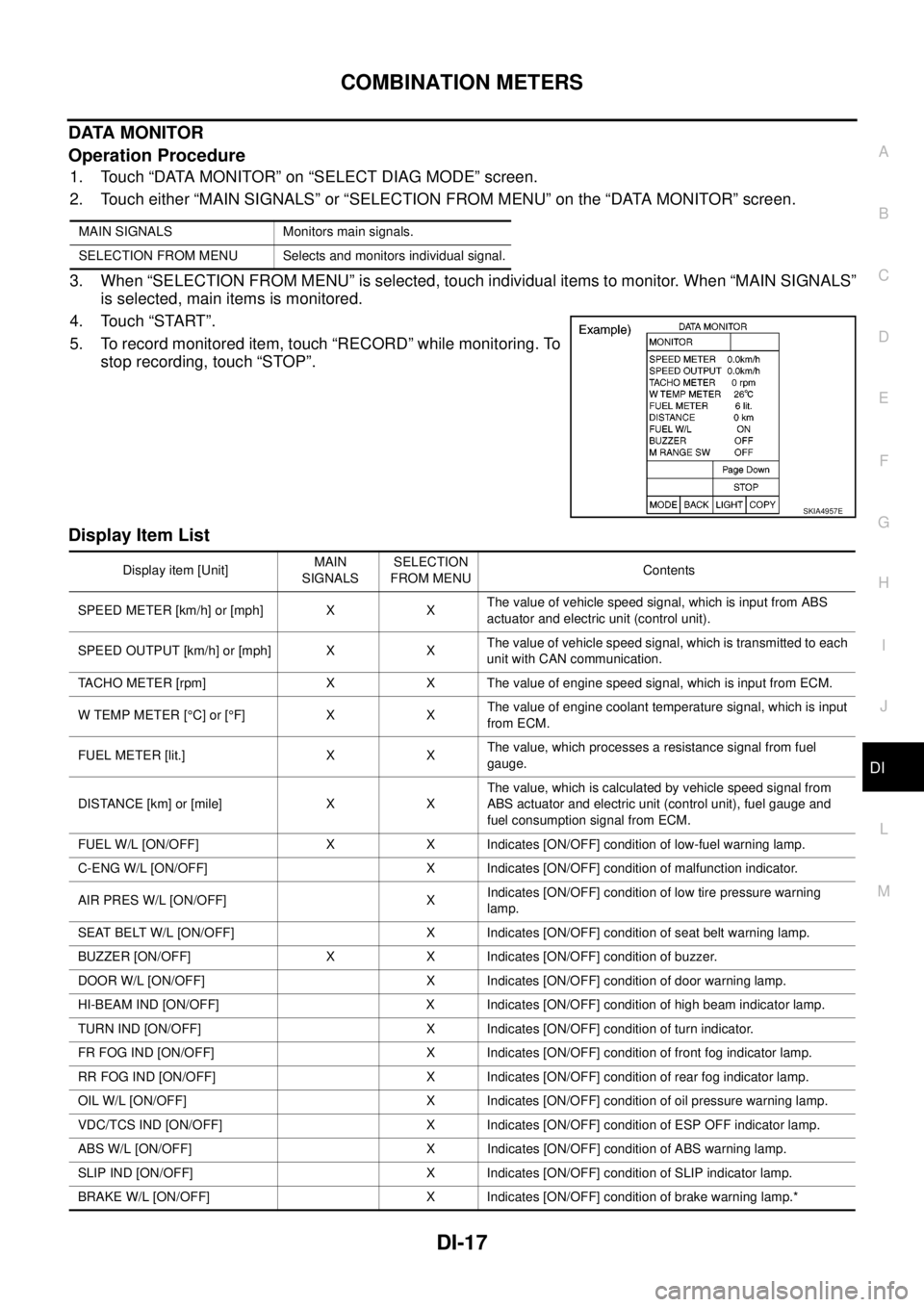
1. Touch “DATA MONITOR” on “SELECT DIAG MODE” screen.
2. Touch either “MAIN SIGNALS” or “SELECTION FROM MENU” on the “DATA MONITOR” screen.
3. When “SELECTION FROM MENU” is selected, touch individual items to monitor. When “MAIN SIGNALS”
is selected, main items is monitored.
4. Touch “START”.
5. To record monitored item, touch “RECORD” while monitoring. To
stop recording, touch “STOP”.
Display Item List
MAIN SIGNALS Monitors main signals.
SELECTION FROM MENU Selects and monitors individual signal.
SKIA4957E
Display item [Unit]MAIN
SIGNALSSELECTION
FROM MENUContents
SPEED METER [km/h] or [mph] X XThe value of vehicle speed signal, which is input from ABS
actuator and electric unit (control unit).
SPEED OUTPUT [km/h] or [mph] X XThe value of vehicle speed signal, which is transmitted to each
unit with CAN communication.
TACHO METER [rpm] X X The value of engine speed signal, which is input from ECM.
W TEMP METER [°C] or [°F] X XThe value of engine coolant temperature signal, which is input
from ECM.
FUEL METER [lit.] X XThe value, which processes a resistance signal from fuel
gauge.
DISTANCE [km] or [mile] X XThe value, which is calculated by vehicle speed signal from
ABS actuator and electric unit (control unit), fuel gauge and
fuel consumption signal from ECM.
FUEL W/L [ON/OFF] X X Indicates [ON/OFF] condition of low-fuel warning lamp.
C-ENG W/L [ON/OFF] X Indicates [ON/OFF] condition of malfunction indicator.
AIR PRES W/L [ON/OFF] XIndicates [ON/OFF] condition of low tire pressure warning
lamp.
SEAT BELT W/L [ON/OFF] X Indicates [ON/OFF] condition of seat belt warning lamp.
BUZZER [ON/OFF] X X Indicates [ON/OFF] condition of buzzer.
DOOR W/L [ON/OFF] X Indicates [ON/OFF] condition of door warning lamp.
HI-BEAM IND [ON/OFF] X Indicates [ON/OFF] condition of high beam indicator lamp.
TURN IND [ON/OFF] X Indicates [ON/OFF] condition of turn indicator.
FR FOG IND [ON/OFF] X Indicates [ON/OFF] condition of front fog indicator lamp.
RR FOG IND [ON/OFF] X Indicates [ON/OFF] condition of rear fog indicator lamp.
OIL W/L [ON/OFF] X Indicates [ON/OFF] condition of oil pressure warning lamp.
VDC/TCS IND [ON/OFF] X Indicates [ON/OFF] condition of ESP OFF indicator lamp.
ABS W/L [ON/OFF] X Indicates [ON/OFF] condition of ABS warning lamp.
SLIP IND [ON/OFF] X Indicates [ON/OFF] condition of SLIP indicator lamp.
BRAKE W/L [ON/OFF] X Indicates [ON/OFF] condition of brake warning lamp.*
Page 928 of 3171

DI-18
COMBINATION METERS
NOTE:
Some items are not available according to vehicle specification.
*: Monitor indicating “OFF” when brake warning lamp is on because of parking brake operation or low brake
fluid level continues.
Trouble DiagnosisEKS00L8M
HOW TO PERFORM TROUBLE DIAGNOSIS
1. Confirm the symptom or customer complaint.
2. Perform preliminary check. Refer toDI-19, "
PRELIMINARY CHECK".
3. According to the symptom chart, make sure of the symptom cause and repair or replace applicable parts.
Refer toDI-19, "
Symptom Chart".
4. Does the meter operate normally? If so, GO TO 5. If not, GO TO 2.
5. INSPECTION END
KEY G W/L [ON/OFF] X Indicates [ON/OFF] condition of KEY warning lamp (green).
KEY R W/L [ON/OFF] X Indicates [ON/OFF] condition of KEY warning lamp (red).
KEY KNOB W/L [ON/OFF] X Indicates [ON/OFF] condition of LOCK warning lamp.
M RANGE SW [ON/OFF] X X Indicates [ON/OFF] condition of manual mode range switch.
NM RANGE SW [ON/OFF] X XIndicates [ON/OFF] condition of except for manual mode range
switch.
AT SFT UP SW [ON/OFF] X X Indicates [ON/OFF] condition of A/T shift-up switch.
AT SFT DWN SW [ON/OFF] X X Indicates [ON/OFF] condition of A/T shift-down switch.
O/D OFF SW [ON/OFF] X Indicates [ON/OFF] condition of OD OFF switch.
BRAKE SW [ON/OFF] X Indicates [ON/OFF] condition of parking brake switch.
AT-M IND [ON/OFF] X X Indicates [ON/OFF] condition of A/T manual mode indicator.
AT-MGEAR[1,2,3,4,5] X XIndicates [1, 2, 3, 4, 5] condition of A/T manual mode gear
position.
P RANGE IND [ON/OFF] X X Indicates [ON/OFF] condition of A/T shift P range indicator.
R RANGE IND [ON/OFF] X X Indicates [ON/OFF] condition of A/T shift R range indicator.
N RANGE IND [ON/OFF] X X Indicates [ON/OFF] condition of A/T shift N range indicator.
D RANGE IND [ON/OFF] X X Indicates [ON/OFF] condition of A/T shift D range indicator.
4 RANGE IND [ON/OFF] X X Indicates [ON/OFF] condition of A/T shift 4 range indicator.
3 RANGE IND [ON/OFF] X X Indicates [ON/OFF] condition of A/T shift 3 range indicator.
2 RANGE IND [ON/OFF] X X Indicates [ON/OFF] condition of A/T shift 2 range indicator.
1 RANGE IND [ON/OFF] X X Indicates [ON/OFF] condition of A/T shift 1range indicator.
O/D OFF W/L [ON/OFF] X Indicates [ON/OFF] condition of OD OFF indicator lamp.
CRUISE IND [ON/OFF] X Indicates [ON/OFF] condition of CRUISE indicator lamp.
SET IND [ON/OFF] X Indicates [ON/OFF] condition of SET indicator lamp.
4WD LOCK SW [ON/OFF] X Indicates [ON/OFF] condition of 4WD LOCK switch.
4WD LOCK IND [ON/OFF] X Indicates [ON/OFF] condition of 4WD LOCK indicator lamp.
4WD W/L [ON/OFF] X Indicates [ON/OFF] condition of 4WD warning lamp.Display item [Unit]MAIN
SIGNALSSELECTION
FROM MENUContents
Page 929 of 3171
COMBINATION METERS
DI-19
C
D
E
F
G
H
I
J
L
MA
B
DI
PRELIMINARY CHECK
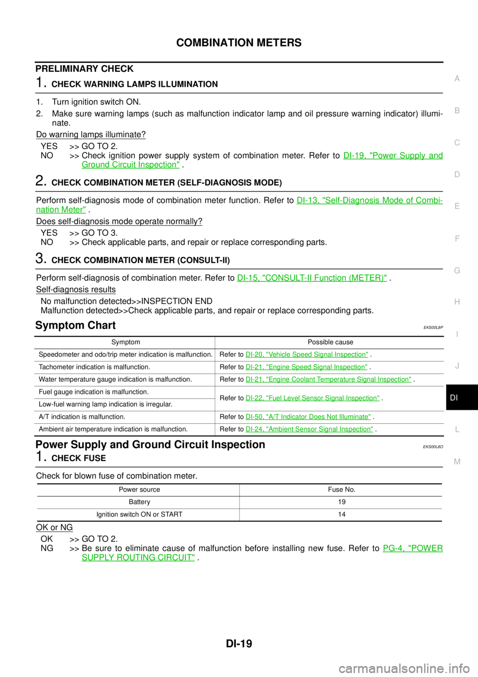
1.CHECK WARNING LAMPS ILLUMINATION
1. Turn ignition switch ON.
2. Make sure warning lamps (such as malfunction indicator lamp and oil pressure warning indicator) illumi-
nate.
Do warning lamps illuminate?
YES >> GO TO 2.
NO >> Check ignition power supply system of combination meter. Refer toDI-19, "
Power Supply and
Ground Circuit Inspection".
2.CHECK COMBINATION METER (SELF-DIAGNOSIS MODE)
Perform self-diagnosis mode of combination meter function. Refer toDI-13, "
Self-Diagnosis Mode of Combi-
nation Meter".
Does self-diagnosis mode operate normally?
YES >> GO TO 3.
NO >> Check applicable parts, and repair or replace corresponding parts.
3.CHECK COMBINATION METER (CONSULT-II)
Perform self-diagnosis of combination meter. Refer toDI-15, "
CONSULT-II Function (METER)".
Self-diagnosis results
No malfunction detected>>INSPECTION END
Malfunction detected>>Check applicable parts, and repair or replace corresponding parts.
Symptom ChartEKS00L8P
Power Supply and Ground Circuit InspectionEKS00L8O
1.CHECK FUSE
Check for blown fuse of combination meter.
OK or NG
OK >> GO TO 2.
NG >> Be sure to eliminate cause of malfunction before installing new fuse. Refer toPG-4, "
POWER
SUPPLY ROUTING CIRCUIT".
Symptom Possible cause
Speedometer and odo/trip meter indication is malfunction. Refer toDI-20, "
Vehicle Speed Signal Inspection".
Tachometer indication is malfunction. Refer toDI-21, "
Engine Speed Signal Inspection".
Water temperature gauge indication is malfunction. Refer toDI-21, "
Engine Coolant Temperature Signal Inspection".
Fuel gauge indication is malfunction.
Refer toDI-22, "
Fuel Level Sensor Signal Inspection".
Low-fuel warning lamp indication is irregular.
A/T indication is malfunction. Refer toDI-50, "
A/T Indicator Does Not Illuminate".
Ambient air temperature indication is malfunction. Refer toDI-24, "
Ambient Sensor Signal Inspection".
Power source Fuse No.
Battery 19
Ignition switch ON or START 14
Page 930 of 3171
DI-20
COMBINATION METERS
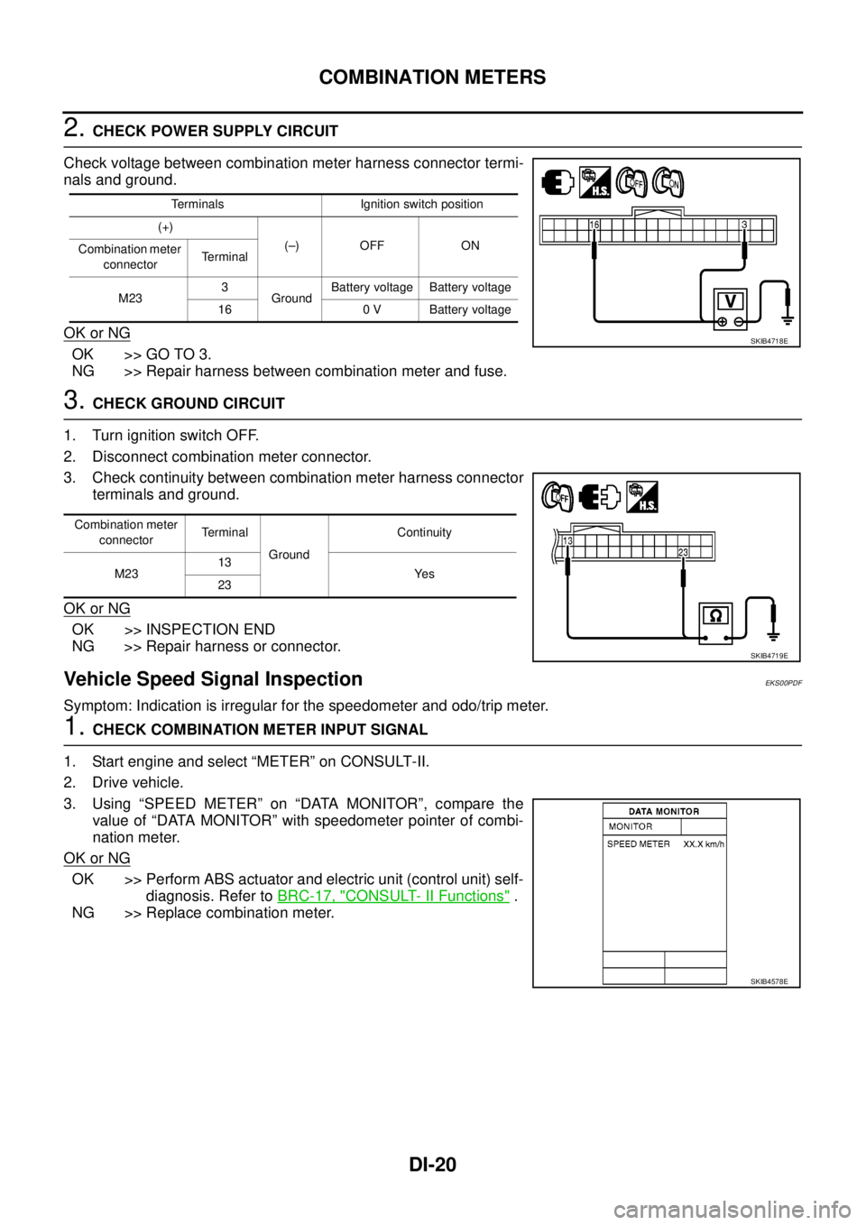
2.CHECK POWER SUPPLY CIRCUIT
Check voltage between combination meter harness connector termi-
nals and ground.
OK or NG
OK >> GO TO 3.
NG >> Repair harness between combination meter and fuse.
3.CHECK GROUND CIRCUIT
1. Turn ignition switch OFF.
2. Disconnect combination meter connector.
3. Check continuity between combination meter harness connector
terminals and ground.
OK or NG
OK >> INSPECTION END
NG >> Repair harness or connector.
Vehicle Speed Signal InspectionEKS00PDF
Symptom: Indication is irregular for the speedometer and odo/trip meter.
1.CHECK COMBINATION METER INPUT SIGNAL
1. Start engine and select “METER” on CONSULT-II.
2. Drive vehicle.
3. Using “SPEED METER” on “DATA MONITOR”, compare the
value of “DATA MONITOR” with speedometer pointer of combi-
nation meter.
OK or NG
OK >> Perform ABS actuator and electric unit (control unit) self-
diagnosis. Refer toBRC-17, "
CONSULT- II Functions".
NG >> Replace combination meter.
Terminals Ignition switch position
(+)
(–) OFF ON
Combination meter
connectorTerminal
M233
GroundBattery voltage Battery voltage
16 0 V Battery voltage
SKIB4718E
Combination meter
connectorTe r m i n a l
GroundContinuity
M2313
Ye s
23
SKIB4719E
SKIB4578E