NISSAN NOTE 2016 Service Repair Manual
Manufacturer: NISSAN, Model Year: 2016, Model line: NOTE, Model: NISSAN NOTE 2016Pages: 3641, PDF Size: 28.72 MB
Page 2851 of 3641
SE-38
< UNIT DISASSEMBLY AND ASSEMBLY >
REAR SEAT
REAR SEAT
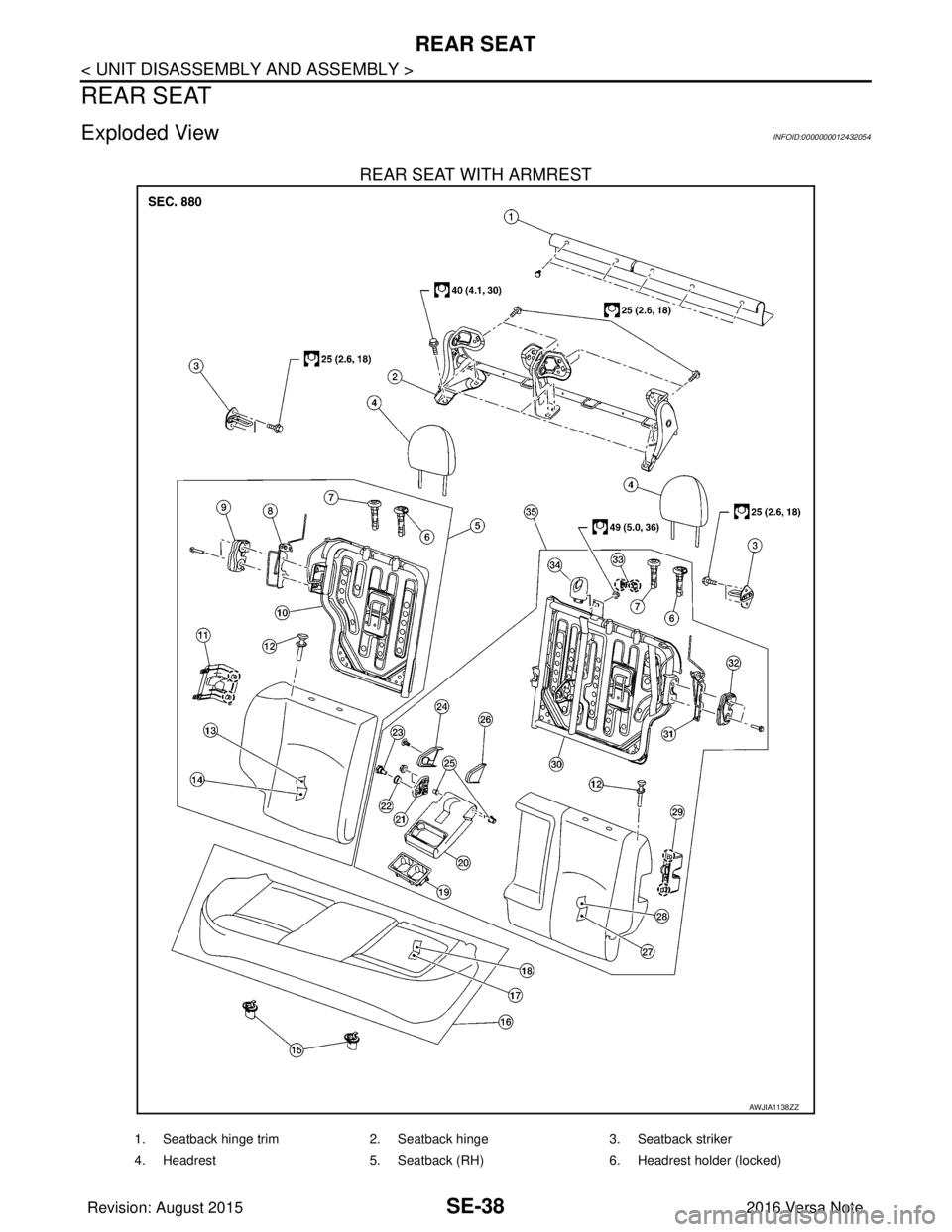
Exploded ViewINFOID:0000000012432054
REAR SEAT WITH ARMREST
AWJIA1138ZZ
1. Seatback hinge trim2. Seatback hinge 3. Seatback striker
4. Headrest 5. Seatback (RH) 6. Headrest holder (locked)
Revision: August 2015 2016 Versa Note
cardiagn.com
Page 2852 of 3641
REAR SEATSE-39
< UNIT DISASSEMBLY AND ASSEMBLY >
C
DE
F
G H
I
K L
M A
B
SE
N
O P
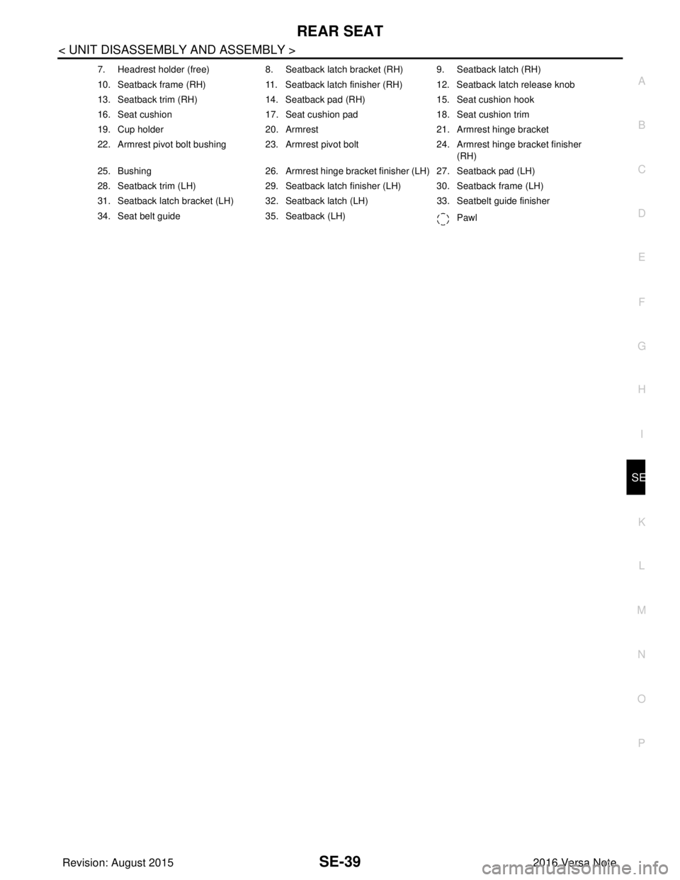
7. Headrest holder (free) 8. Seatback latch bracket (RH) 9. Seatback latch (RH)
10. Seatback frame (RH) 11. Seatback latch finisher (RH) 12. Seatback latch release knob
13. Seatback trim (RH) 14. Seatback pad (RH) 15. Seat cushion hook
16. Seat cushion 17. Seat cushion pad 18. Seat cushion trim
19. Cup holder 20. Armrest 21. Armrest hinge bracket
22. Armrest pivot bolt bushing 23. Armrest pivot bolt 24. Armrest hinge bracket finisher
(RH)
25. Bushing 26. Armrest hinge bracket finisher (LH) 27. Seatback pad (LH)
28. Seatback trim (LH) 29. Seatback latch finisher (LH) 30. Seatback frame (LH)
31. Seatback latch bracket (LH) 32. Seatback latch (LH) 33. Seatbelt guide finisher
34. Seat belt guide 35. Seatback (LH)
Pawl
Revision: August 2015 2016 Versa Note
cardiagn.com
Page 2853 of 3641
SE-40
< UNIT DISASSEMBLY AND ASSEMBLY >
REAR SEAT
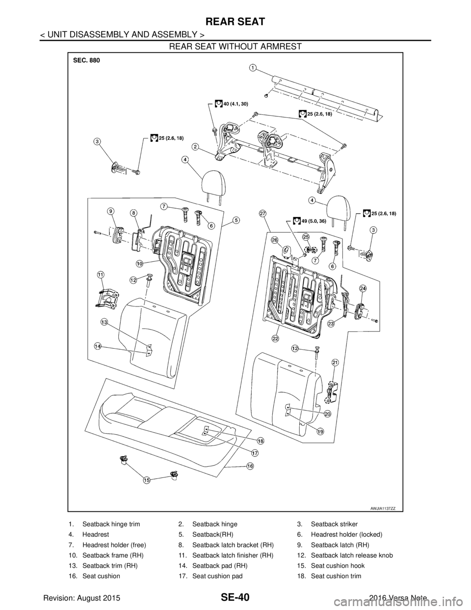
REAR SEAT WITHOUT ARMREST
AWJIA1137ZZ
1. Seatback hinge trim2. Seatback hinge 3. Seatback striker
4. Headrest 5. Seatback(RH) 6. Headrest holder (locked)
7. Headrest holder (free) 8. Seatback latch bracket (RH) 9. Seatback latch (RH)
10. Seatback frame (RH) 11. Seatback latch finisher (RH) 12. Seatback latch release knob
13. Seatback trim (RH) 14. Seatback pad (RH) 15. Seat cushion hook
16. Seat cushion 17. Seat cushion pad 18. Seat cushion trim
Revision: August 2015 2016 Versa Note
cardiagn.com
Page 2854 of 3641
REAR SEATSE-41
< UNIT DISASSEMBLY AND ASSEMBLY >
C
DE
F
G H
I
K L
M A
B
SE
N
O P
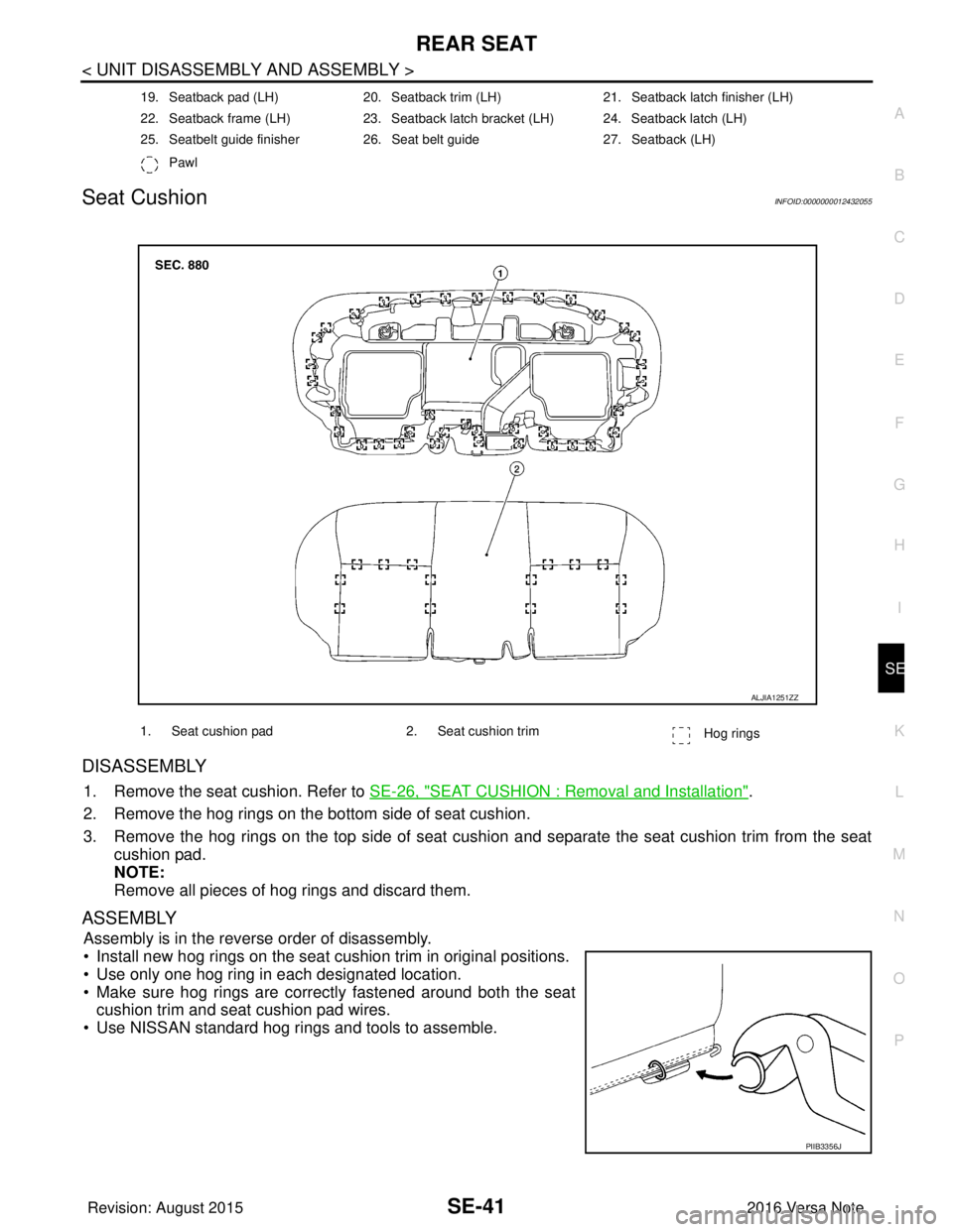
Seat CushionINFOID:0000000012432055
DISASSEMBLY
1. Remove the seat cushion. Refer to SE-26, "SEAT CUSHION : Removal and Installation".
2. Remove the hog rings on the bottom side of seat cushion.
3. Remove the hog rings on the top side of seat cushi on and separate the seat cushion trim from the seat
cushion pad.
NOTE:
Remove all pieces of hog rings and discard them.
ASSEMBLY
Assembly is in the reverse order of disassembly.
• Install new hog rings on the seat cushion trim in original positions.
• Use only one hog ring in each designated location.
• Make sure hog rings are correctly fastened around both the seat cushion trim and seat cushion pad wires.
• Use NISSAN standard hog rings and tools to assemble.
19. Seatback pad (LH) 20. Seatback trim (LH) 21. Seatback latch finisher (LH)
22. Seatback frame (LH) 23. Seatback latch bracket (LH) 24. Seatback latch (LH)
25. Seatbelt guide finisher 26. Seat belt guide 27. Seatback (LH)
Pawl
1. Seat cushion pad 2. Seat cushion trim
Hog rings
ALJIA1251ZZ
PIIB3356J
Revision: August 2015 2016 Versa Note
cardiagn.com
Page 2855 of 3641
SE-42
< UNIT DISASSEMBLY AND ASSEMBLY >
REAR SEAT
Seatback
INFOID:0000000012432056
DISASSEMBLY
Seatback (LH)
1. Remove the seatback (LH). Refer to SE-26, "SEATBACK : Removal and Installation".
2. Remove the headrest.
3. Release clips and remove latch finisher.
4. Release pawls and remove the seat belt guide finisher.
5. Remove nut and the seat belt guide.
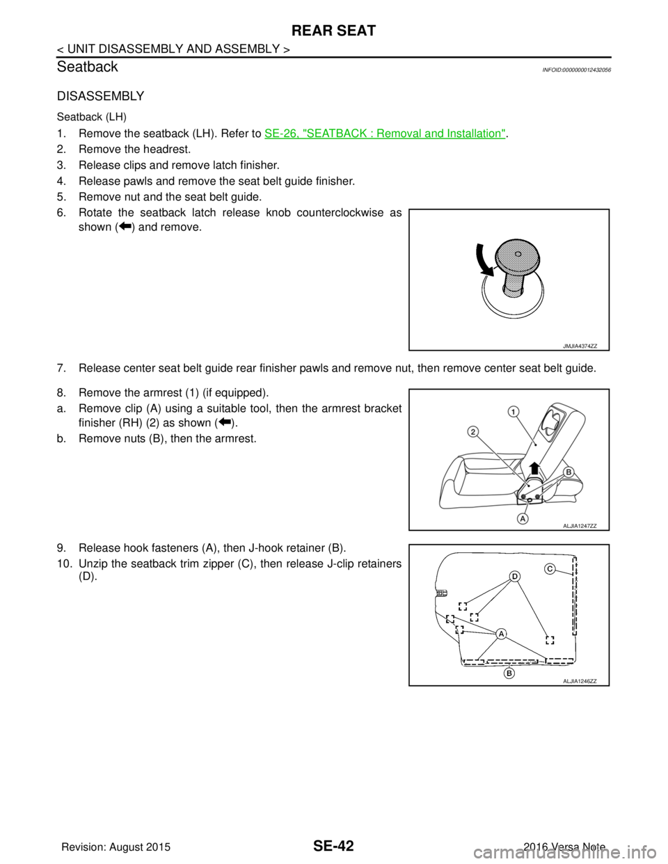
6. Rotate the seatback latch release knob counterclockwise as shown ( ) and remove.
7. Release center seat belt guide rear finisher pawls and remove nut, then remove center seat belt guide.
8. Remove the armrest (1) (if equipped).
a. Remove clip (A) using a suitable tool, then the armrest bracket finisher (RH) (2) as shown ( ).
b. Remove nuts (B), then the armrest.
9. Release hook fasteners (A), then J-hook retainer (B).
10. Unzip the seatback trim zipper (C), then release J-clip retainers (D).
JMJIA4374ZZ
ALJIA1247ZZ
ALJIA1246ZZ
Revision: August 2015 2016 Versa Note
cardiagn.com
Page 2856 of 3641
REAR SEATSE-43
< UNIT DISASSEMBLY AND ASSEMBLY >
C
DE
F
G H
I
K L
M A
B
SE
N
O P
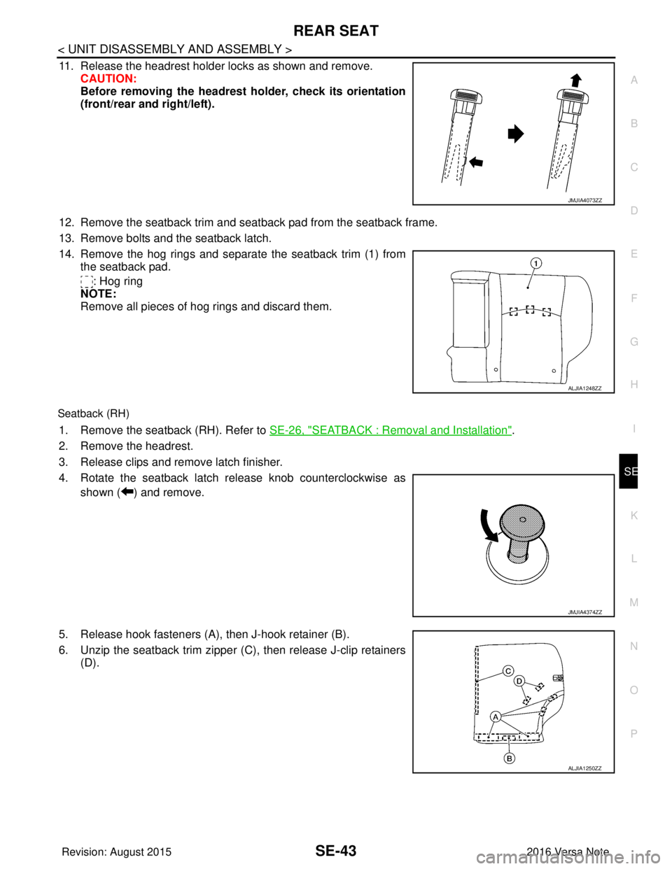
11. Release the headrest holder locks as shown and remove. CAUTION:
Before removing the headrest holder, check its orientation
(front/rear and right/left).
12. Remove the seatback trim and seatback pad from the seatback frame.
13. Remove bolts and the seatback latch.
14. Remove the hog rings and separate the seatback trim (1) from the seatback pad.
: Hog ring
NOTE:
Remove all pieces of hog rings and discard them.
Seatback (RH)
1. Remove the seatback (RH). Refer to SE-26, "SEATBACK : Removal and Installation".
2. Remove the headrest.
3. Release clips and remove latch finisher.
4. Rotate the seatback latch release knob counterclockwise as shown ( ) and remove.
5. Release hook fasteners (A), then J-hook retainer (B).
6. Unzip the seatback trim zipper (C), then release J-clip retainers (D).
JMJIA4073ZZ
ALJIA1248ZZ
JMJIA4374ZZ
ALJIA1250ZZ
Revision: August 2015 2016 Versa Note
cardiagn.com
Page 2857 of 3641
SE-44
< UNIT DISASSEMBLY AND ASSEMBLY >
REAR SEAT
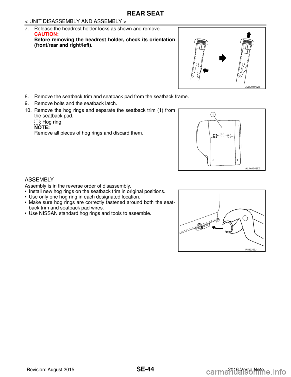
7. Release the headrest holder locks as shown and remove.CAUTION:
Before removing the headrest holder, check its orientation
(front/rear and right/left).
8. Remove the seatback trim and seatback pad from the seatback frame.
9. Remove bolts and the seatback latch.
10. Remove the hog rings and separate the seatback trim (1) from the seatback pad.
: Hog ring
NOTE:
Remove all pieces of hog rings and discard them.
ASSEMBLY
Assembly is in the reverse order of disassembly.
• Install new hog rings on the seatback trim in original positions.
• Use only one hog ring in each designated location.
• Make sure hog rings are correctly fastened around both the seat-
back trim and seatback pad wires.
• Use NISSAN standard hog rings and tools to assemble.
JMJIA4073ZZ
ALJIA1249ZZ
PIIB3356J
Revision: August 2015 2016 Versa Note
cardiagn.com
Page 2858 of 3641

SEC-1
BODY EXTERIOR, DOORS, ROOF & VEHICLE SECURITY
C
DE
F
G H
I
J
L
M
SECTION SEC
A
B
SEC
N
O P
CONTENTS
SECURITY CONTROL SYSTEM
WITH INTELLIGENT KEY SYSTEM
PRECAUTION ....... ........................................
5
PRECAUTIONS .............................................. .....5
Precaution for Supplemental Restraint System
(SRS) "AIR BAG" and "SEAT BELT PRE-TEN-
SIONER" ............................................................. ......
5
Precaution for Work ..................................................5
PREPARATION ............................................6
PREPARATION .............................................. .....6
Special Service Tool ........................................... ......6
SYSTEM DESCRIPTION ..............................7
COMPONENT PARTS ................................... .....7
Component Parts Location .................................. ......7
CVT Shift Selector (Park Position Switch) ................9
BCM ..........................................................................9
ECM ..........................................................................9
IPDM E/R ................................................................10
NATS Antenna Amp. ...............................................10
Combination Meter ..................................................10
Door Switch .............................................................10
Outside Key Antenna ..............................................10
Inside Key Antenna .................................................10
Remote Keyless Entry Receiver .............................10
Intelligent Key ..........................................................10
Push-button Ignition Switch .....................................10
Security Indicator Lamp ...................................... ....10
Starter Relay ...........................................................10
Stop Lamp Switch ...................................................11
Transmission Range Switch ....................................11
SYSTEM .............................................................12
INTELLIGENT KEY SYSTEM/ENGINE START
FUNCTION ............................................................. ....
12
INTELLIGENT KEY SYSTEM/ENGINE START
FUNCTION : System Description ............................
12
NISSAN ANTI-THEFT SYSTEM ................................14
NISSAN ANTI-THEFT SYST EM : System De-
scription ............................................................... ....
15
DIAGNOSIS SYSTEM (BCM) ...........................18
COMMON ITEM ..................................................... ....18
COMMON ITEM : CONSULT Function (BCM -
COMMON ITEM) .....................................................
18
INTELLIGENT KEY ................................................ ....19
INTELLIGENT KEY : CONSULT Function (BCM -
INTELLIGENT KEY) ................................................
19
THEFT ALM ........................................................... ....21
THEFT ALM : CONSULT Function (BCM -
THEFT) ....................................................................
21
IMMU ...................................................................... ....21
IMMU : CONSULT Function (BCM - IMMU) ............21
ECU DIAGNOSIS INFORMATION ..............23
ECM, IPDM E/R, BCM .......................................23
List of ECU Reference ......................................... ....23
WIRING DIAGRAM ......................................24
INTELLIGENT KEY SYSTEM/ENGINE
START FUNCTION ...........................................
24
Wiring Diagram .................................................... ....24
NVIS - WITH INTELLIGENT KEY SYSTEM .....37
Wiring Diagram ........................................................37
BASIC INSPECTION ...................................46
DIAGNOSIS AND REPAIR WORK FLOW .......46
Work Flow ............................................................ ....46
ADDITIONAL SERVICE WHEN REPLACING
CONTROL UNIT ................................................
49
ECM ........................................................................ ....49
Revision: August 2015 2016 Versa Note
cardiagn.com
Page 2859 of 3641

SEC-2
ECM : Description ...................................................49
ECM : Work Procedure ...........................................49
BCM ........................................................................ ...49
BCM : Description ...................................................49
BCM : Work Procedure ...........................................49
DTC/CIRCUIT DIAGNOSIS ...................... ...51
P1610 LOCK MODE ....................................... ...51
Description ........................................................... ...51
DTC Logic ...............................................................51
Diagnosis Procedure ..............................................51
P1611 ID DISCORD, IMMU-ECM ......................52
DTC Logic ............................................................ ...52
Diagnosis Procedure ..............................................52
P1612 CHAIN OF ECM-IMMU ...........................53
DTC Logic ............................................................ ...53
Diagnosis Procedure ..............................................53
B2192 ID DISCORD, IMMU-ECM ......................54
DTC Logic ............................................................ ...54
Diagnosis Procedure ..............................................54
B2193 CHAIN OF ECM-IMMU ...........................55
DTC Logic ............................................................ ...55
Diagnosis Procedure ..............................................55
B2195 ANTI-SCANNING ...................................56
DTC Logic ............................................................ ...56
Diagnosis Procedure ..............................................56
B2196 DONGLE UNIT .......................................57
Description ........................................................... ...57
DTC Logic ...............................................................57
Diagnosis Procedure ..............................................57
B2198 NATS ANTENNA AMP. .........................59
DTC Logic ............................................................ ...59
Diagnosis Procedure ..............................................59
B2555 STOP LAMP ...........................................62
DTC Logic ............................................................ ...62
Diagnosis Procedure ..............................................62
Component Inspection ............................................63
B2556 PUSH-BUTTON IGNITION SWITCH .....65
DTC Logic ...............................................................65
Diagnosis Procedure ..............................................65
Component Inspection ............................................66
B2557 VEHICLE SPEED ...................................67
DTC Logic ............................................................ ...67
Diagnosis Procedure ..............................................67
B2601 SHIFT POSITION ...................................68
DTC Logic ............................................................ ...68
Diagnosis Procedure ..............................................68
B2602 SHIFT POSITION ...................................70
DTC Logic ............................................................ ...70
Diagnosis Procedure ...............................................70
Component Inspection ............................................72
B2603 SHIFT POSITION ...................................73
DTC Logic ...............................................................73
Diagnosis Procedure ...............................................73
Component Inspection (Transmission Range
Switch) ....................................................................
76
Component Inspection [CVT Shift Selector (Park
Position Switch)] .....................................................
76
B2604 SHIFT POSITION ...................................77
DTC Logic ...............................................................77
Diagnosis Procedure ...............................................77
Component Inspection ............................................79
B2605 SHIFT POSITION ...................................80
DTC Logic ...............................................................80
Diagnosis Procedure ...............................................80
B2608 STARTER RELAY .................................82
DTC Logic ...............................................................82
Diagnosis Procedure ...............................................82
Component Inspection ............................................83
B260F ENGINE STATUS ..................................84
Description ..............................................................84
DTC Logic ...............................................................84
Diagnosis Procedure ...............................................84
B261F ASCD CLUTCH SWITCH ......................85
DTC Logic ...............................................................85
Diagnosis Procedure ...............................................85
Component Inspection ............................................87
B2620 PARK/NEUTRAL POSITION SWITCH ...88
DTC Logic ............................................................ ...88
Diagnosis Procedure ...............................................88
Component Inspection ............................................90
B26E8 CLUTCH INTERLOCK SWITCH ...........91
DTC Logic ............................................................ ...91
Diagnosis Procedure ...............................................91
Component Inspection (Clutch Interlock Switch) ....93
B26F3 STARTER CONTROL RELAY ..............94
DTC Logic ............................................................ ...94
Diagnosis Procedure ...............................................94
B26F4 STARTER CONTROL RELAY ..............95
DTC Logic ............................................................ ...95
Diagnosis Procedure ...............................................95
B26F7 BCM .......................................................96
DTC Logic ............................................................ ...96
Diagnosis Procedure ...............................................96
B26FB CLUTCH SWITCH .................................97
DTC Logic ............................................................ ...97
Diagnosis Procedure ...............................................97
Revision: August 2015 2016 Versa Note
cardiagn.com
Page 2860 of 3641

SEC-3
C
DE
F
G H
I
J
L
M A
B
SEC
N
O P
B26FC KEY REGISTRATION ........................ ....98
DTC Logic ........................................................... ....98
Diagnosis Procedure ...............................................98
B210B STARTER CONTROL RELAY ...............99
DTC Logic ........................................................... ....99
Diagnosis Procedure ...............................................99
B210C STARTER CONTROL RELAY .............100
DTC Logic ........................................................... ..100
Diagnosis Procedure .............................................100
B210D STARTER RELAY ................................102
DTC Logic .............................................................102
Diagnosis Procedure .............................................102
B210E STARTER RELAY ................................104
DTC Logic .............................................................104
Diagnosis Procedure .............................................104
B210F SHIFT POSITION/CLUTCH INTER-
LOCK SWITCH .................................................
106
DTC Logic ........................................................... ..106
Diagnosis Procedure .............................................106
B2110 SHIFT POSITION/CLUTCH INTER-
LOCK SWITCH .................................................
108
DTC Logic ........................................................... ..108
Diagnosis Procedure .............................................108
VEHICLE SECURITY INDICATOR ..................110
Description .......................................................... ..110
Component Function Check ................................110
Diagnosis Procedure .............................................110
SYMPTOM DIAGNOSIS ............................112
ENGINE DOES NOT START WHEN INTELLI-
GENT KEY IS INSIDE OF VEHICLE .............. ..
112
Description .......................................................... ..112
Diagnosis Procedure .............................................112
SECURITY INDICATOR LAMP DOES NOT
TURN ON OR BLINK .......................................
113
Description .......................................................... ..113
Diagnosis Procedure .............................................113
REMOVAL AND INSTALLATION .............114
NATS ANTENNA AMP. .................................. ..114
Removal and Installation .......................................114
PUSH-BUTTON IGNITION SWITCH .............. ..115
Removal and Installation .......................................115
REMOTE KEYLESS ENTRY RECEIVER ...... ..116
Removal and Installation .......................................116
WITHOUT INTELLIGE NT KEY SYSTEM
PRECAUTION ....... .....................................
117
PRECAUTIONS .............................................. ..117
Precaution for Supplemental Restraint System
(SRS) "AIR BAG" and "SEAT BELT PRE-TEN-
SIONER" ............................................................. ..
117
Precaution for Work ...............................................117
PREPARATION .........................................118
PREPARATION ...............................................118
Special Service Tool ............................................ ..118
SYSTEM DESCRIPTION ...........................119
COMPONENT PARTS ....................................119
NISSAN VEHICLE IMMOBILIZER SYSTEM-NATS ..119
NISSAN VEHICLE IMMOBILIZER SYSTEM-
NATS : Component Parts Location .......................
119
NISSAN VEHICLE IMMOBILIZER SYSTEM-
NATS : CVT Shift Selector (Park Position Switch) ..
121
NISSAN VEHICLE IMMOBILIZER SYSTEM-
NATS : BCM ..........................................................
121
NISSAN VEHICLE IMMOBILIZER SYSTEM-
NATS : ECM ..........................................................
121
NISSAN VEHICLE IMMOBILIZER SYSTEM-
NATS : IPDM E/R ..................................................
121
NISSAN VEHICLE IMMOBILIZER SYSTEM-
NATS : Combination Meter ....................................
121
NISSAN VEHICLE IMMOBILIZER SYSTEM-
NATS : Door Switch ...............................................
122
NISSAN VEHICLE IMMOBILIZER SYSTEM-
NATS : Remote Keyless Entry Receiver ...............
122
NISSAN VEHICLE IMMOBILIZER SYSTEM-
NATS : Security Indicator Lamp .......................... ..
122
NISSAN VEHICLE IMMOBILIZER SYSTEM-
NATS : Starter Relay .............................................
122
NISSAN VEHICLE IMMOBILIZER SYSTEM-
NATS : Stop Lamp Switch .....................................
122
NISSAN VEHICLE IMMOBILIZER SYSTEM-
NATS : Transmission Range Switch .....................
122
SYSTEM ..........................................................123
NISSAN VEHICLE IMMOBILIZER SYSTEM-NATS ..123
NISSAN VEHICLE IMMOBILIZER SYSTEM-
NATS : System Diagram .......................................
123
NISSAN VEHICLE IMMOBILIZER SYSTEM-
NATS : System Description ...................................
123
DIAGNOSIS SYSTEM (BCM) .........................125
COMMON ITEM ..................................................... ..125
COMMON ITEM : CONSULT Function (BCM -
COMMON ITEM) ...................................................
125
IMMU ...................................................................... ..126
IMMU : CONSULT Function (BCM - IMMU) ..........126
DIAGNOSIS SYSTEM (IPDM E/R) .................127
Diagnosis Description ............................................127
CONSULT Function (IPDM E/R) ...........................128
ECU DIAGNOSIS INFORMATION ............131
Revision: August 2015 2016 Versa Note
cardiagn.com