NISSAN NOTE 2016 Service Repair Manual
Manufacturer: NISSAN, Model Year: 2016, Model line: NOTE, Model: NISSAN NOTE 2016Pages: 3641, PDF Size: 28.72 MB
Page 3531 of 3641

WCS-16
< SYSTEM DESCRIPTION >
DIAGNOSIS SYSTEM (COMBINATION METER)
WARNING HISTORY
W/L ON HISTORY
• Stores histories when warning/indicator lamp is turned on.
• “W/L ON HISTORY” indicates the “TIME” when the warning/ indicator lamp is turned on.
• The “TIME” above is:
- 0: The condition that the warning/indicator lamp has been turned on 1 or more times after starting the engine and waiting for 30 seconds.
- 1 - 39: The number of times the engine was restarted after the 0 condition.
- NO W/L ON HISTORY: Stores NO (0) turning on history of warning/indicator lamp.
NOTE:
• W/L ON HISTORY is not stored for approximately 30 seconds after the engine starts.
• Brake warning lamp does not store any history when the parking brake is applied or the brake fluid level gets low.
TYPE B
TYPE B : On Board Diagnosis FunctionINFOID:0000000012542984
ON BOARD DIAGNOSIS
The following meter functions can be checked during Combination Meter Self-Diagnosis Mode:
• Pointer sweep of speedometer, tachometer and gauges.
• Illumination of all lamps/LEDs that are controlled by the combination meter (regardless of switch status).
• Error code
STARTING COMBINATION ME TER SELF-DIAGNOSIS MODE
NOTE:
• Check combination meter power supply and ground circuits if self-diagnosis mode does not start. Refer to
MWI-98, "
COMBINATION METER : Diagnosis Procedure". Replace combination meter if power supply and
ground circuits are found to be normal and self-diagnosis mode does not start. Refer to MWI-115, "
Removal
and Installation".
• Combination meter self-diagnosis mode will function with the ignition switch in ON. Combination meter self- diagnosis mode will exit upon turning the ignition switch to OFF.
METHOD OF STARTING
1. Turn ignition switch to OFF.
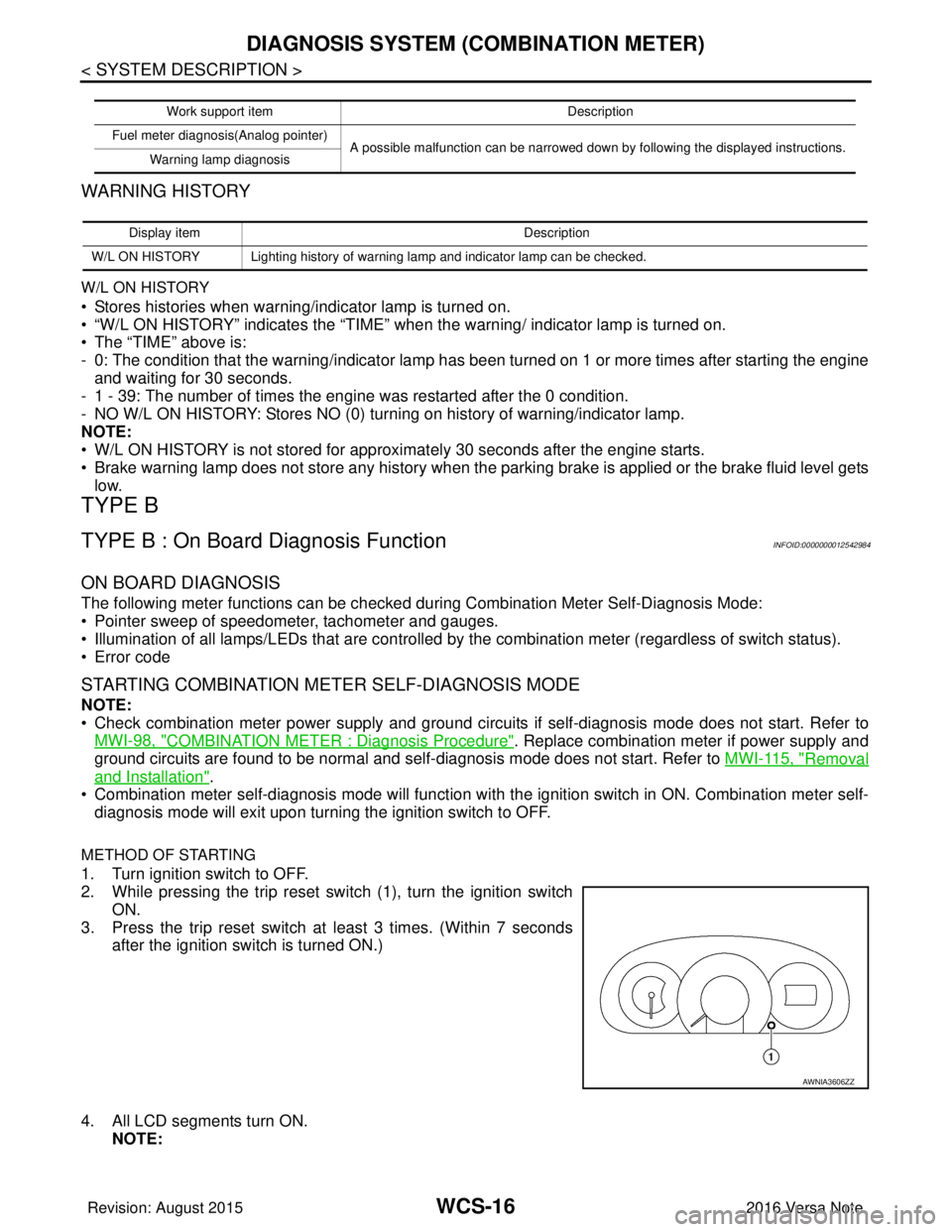
2. While pressing the trip reset switch (1), turn the ignition switch
ON.
3. Press the trip reset switch at least 3 times. (Within 7 seconds
after the ignition switch is turned ON.)
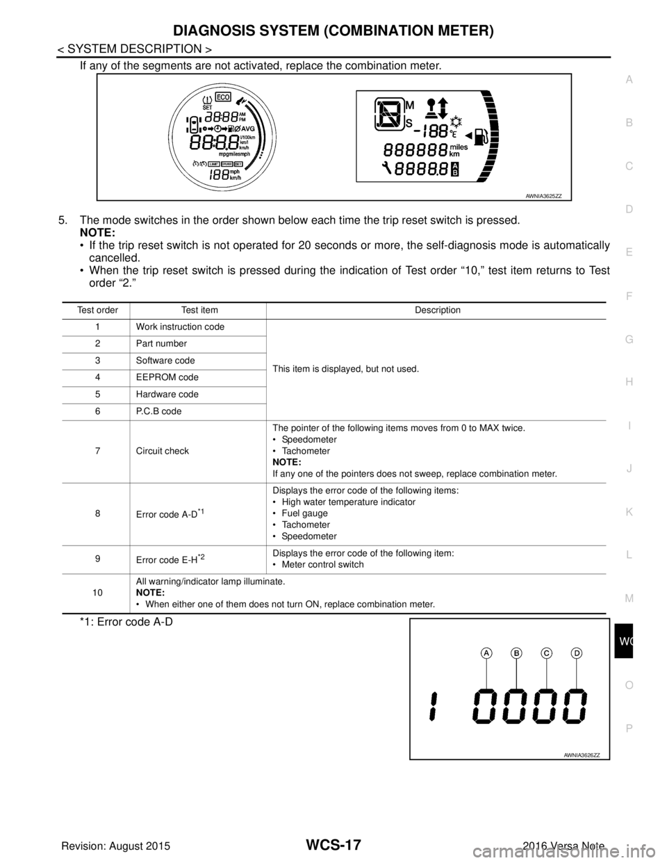
4. All LCD segments turn ON. NOTE:
Work support item Description
Fuel meter diagnosis(Analog pointer) A possible malfunction can be narrowed down by following the displayed instructions.
Warning lamp diagnosis
Display item Description
W/L ON HISTORY Lighting history of warning lamp and indicator lamp can be checked.
AWNIA3606ZZ
Revision: August 2015 2016 Versa Note
cardiagn.com
Page 3532 of 3641

WCS
DIAGNOSIS SYSTEM (COMBINATION METER)WCS-17
< SYSTEM DESCRIPTION >
C
DE
F
G H
I
J
K L
M B A
O P
If any of the segments are not activa ted, replace the combination meter.
5. The mode switches in the order shown below each time the trip reset switch is pressed. NOTE:
• If the trip reset switch is not operated for 20 sec onds or more, the self-diagnosis mode is automatically
cancelled.
• When the trip reset switch is pressed during the indica tion of Test order “10,” test item returns to Test
order “2.”
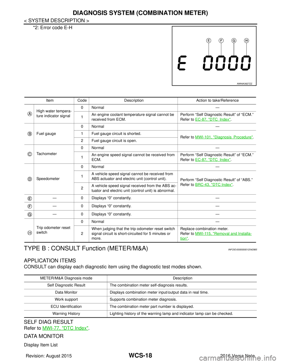
*1: Error code A-D
AWNIA3625ZZ
Test order Test item Description
1 Work instruction code
This item is displayed, but not used.
2 Part number
3 Software code
4 EEPROM code
5 Hardware code
6 P.C.B code
7 Circuit check
The pointer of the following items moves from 0 to MAX twice.
• Speedometer
• Tachometer
NOTE:
If any one of the pointers does not sweep, replace combination meter.
8 Error code A-D
*1
Displays the error code of the following items:
• High water temperature indicator
• Fuel gauge
• Tachometer
• Speedometer
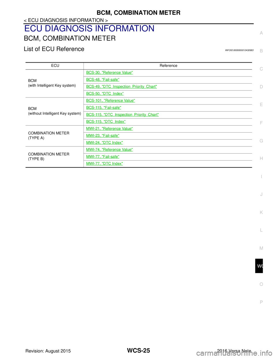
9 Error code E-H
*2Displays the error code of the following item:
• Meter control switch
10 All warning/indicator lamp illuminate.
NOTE:
• When either one of them does not turn ON, replace combination meter.
AWNIA3626ZZ
Revision: August 2015
2016 Versa Note
cardiagn.com
Page 3533 of 3641

WCS-18
< SYSTEM DESCRIPTION >
DIAGNOSIS SYSTEM (COMBINATION METER)
*2: Error code E-H
TYPE B : CONSULT Function (METER/M&A)INFOID:0000000012542985
APPLICATION ITEMS
CONSULT can display each diagnostic item using the diagnostic test modes shown.
SELF DIAG RESULT
Refer to MWI-77, "DTC Index".
DATA MONITOR
Display Item List
AWNIA3627ZZ
Item Code Description Action to take/Reference
High water tempera-
ture indicator signal 0Normal
—
1 An engine coolant temperature signal cannot be
received from ECM. Perform “Self Diagnostic Result” of “ECM.”
Refer to
EC-87, "
DTCIndex".
Fuel gauge 0Normal
—
1 Fuel gauge circuit is shorted. Refer to MWI-101, "
DiagnosisProcedure".
2 Fuel gauge circuit is open.
Tachometer 0Normal
—
1 An engine speed signal cannot be received from
ECM. Perform “Self Diagnostic Result” of “ECM.”
Refer to
EC-87, "
DTCIndex".
Speedometer 0Normal
—
1 A vehicle speed signal cannot be received from
ABS actuator and electric unit (control unit).
Perform “Self Diagnostic Result” of “ABS.”
Refer to BRC-43, "
DTC Index".
2 A vehicle speed signal re
ceived from the ABS ac-
tuator and electric unit (control unit) is abnormal.
— 0 Displays “0” constantly. —
— 0 Displays “0” constantly. —
— 0 Displays “0” constantly. —
Trip odometer reset
switch 0Normal
—
2 When judging that the trip odometer reset switch
signal circuit is short-circuited for 5 minutes or
more. Replace combination meter.
Refer to
MWI-115, "
Removal and Installa-
tion".
METER/M&A Diagnosis mode Description
Self Diagnostic Result The combination meter self-diagnosis results.
Data Monitor Displays combination meter input/output data in real time.
Work support Supports combination meter diagnosis.
ECU Identification The combination meter part number is displayed.
Warning History Lighting history of the warning lamp and indicator lamp can be checked.
Revision: August 2015 2016 Versa Note
cardiagn.com
Page 3534 of 3641
![NISSAN NOTE 2016 Service Repair Manual WCS
DIAGNOSIS SYSTEM (COMBINATION METER)WCS-19
< SYSTEM DESCRIPTION >
C
DE
F
G H
I
J
K L
M B A
O P
X: Applicable
Display item [Unit] MAIN
SIGNALS Description
SPEED METER
[mph] or [km/h] X Displays the NISSAN NOTE 2016 Service Repair Manual WCS
DIAGNOSIS SYSTEM (COMBINATION METER)WCS-19
< SYSTEM DESCRIPTION >
C
DE
F
G H
I
J
K L
M B A
O P
X: Applicable
Display item [Unit] MAIN
SIGNALS Description
SPEED METER
[mph] or [km/h] X Displays the](/img/5/57363/w960_57363-3533.png)
WCS
DIAGNOSIS SYSTEM (COMBINATION METER)WCS-19
< SYSTEM DESCRIPTION >
C
DE
F
G H
I
J
K L
M B A
O P
X: Applicable
Display item [Unit] MAIN
SIGNALS Description
SPEED METER
[mph] or [km/h] X Displays the value of vehicle speed signal.
SPEED OUTPUT
[mph] or [km/h] X
Displays the value of vehicle speed signal, which is transmitted to each unit with
CAN communication.
ODO OUTPUT
[mph] or [km/h] Displays odometer signal value transmitted to other units via CAN communica-
tion.
TACHO METER
[rpm] X Displays the value of engine speed signal, which is input from ECM.
FUEL METER
[L] X Displays the fuel level.
W TEMP METER
[ ° C] or [ °F] X Displays the value of engine coolant temperature signal, which is input from ECM.
ABS W/L
[On/Off] Displays [ON/OFF] condition of ABS warning indicator
VDC/TCS IND
[ON/OFF] Displays [ON/OFF] condition of VDC OFF indicator lamp.
SLIP IND
[ON/OFF] Displays [ON/OFF] condition of SLIP indicator lamp.
BRAKE W/L
[On/Off] Displays [ON/OFF] condition of brake warning indicator.
DOOR W/L
[On/Off] Displays [ON/OFF] condition of door warning indicator.
HI-BEAM IND
[On/Off] Displays [ON/OFF] condition of high beam indicator.
TURN IND
[On/Off] Displays [ON/OFF] condition of turn indicator.
LIGHT IND
[On/Off] Displays [ON/OFF] condition of light indicator.
OIL W/L
[On/Off] Displays [ON/OFF] condition of engine oil pressure warning indicator.
MIL
[On/Off] Displays [ON/OFF] condition of malfunction indicator.
CRUISE IND
[Off] Displays [ON/OFF] cond
ition of CRUISE indicator.
O/D OFF IND
[On/Off] Displays [ON/OFF] condition of O/D OFF indicator.
FUEL W/L
[On/Off] Displays [ON/OFF] condition of low-fuel warning indicator.
PASS BUCKLE SW
[On/Off] Status of seat belt buckle switch RH.
AIR PRES W/L
[ON/OFF] Displays [ON/OFF] condition of tire pressure warning lamp.
KEY G/Y W/L
[ON/OFF] Displays [ON/OFF] condition of key warning lamp.
EPS W/L
[On/Off] Displays [ON/OFF] condition of EPS indicator.
FUEL CAP W/L
[Off] Displays [ON/OFF] condition of loose fuel cap warning message.
PKB SW
[On/Off] Status of parking brake switch.
Revision: August 2015
2016 Versa Note
cardiagn.com
Page 3535 of 3641

WCS-20
< SYSTEM DESCRIPTION >
DIAGNOSIS SYSTEM (COMBINATION METER)
NOTE:
Some items are not available according to vehicle specification.
WORK SUPPORT
WARNING HISTORY
W/L ON HISTORY
• Stores histories when warning/indicator lamp is turned on.
• “W/L ON HISTORY” indicates the “TIME” when the warning/ indicator lamp is turned on.
• The “TIME” above is:
- 0: The condition that the warning/indicator lamp has been turned on 1 or more times after starting the engine and waiting for 30 seconds.
- 1 - 39: The number of times the engine was restarted after the 0 condition.
- NO W/L ON HISTORY: Stores NO (0) turning on history of warning/indicator lamp.
NOTE:
• W/L ON HISTORY is not stored for approximately 30 seconds after the engine starts.
• Brake warning lamp does not store any history when the parking brake is applied or the brake fluid level gets low.
BUCKLE SW
[On/Off] Status of seat belt buckle switch (LH).
BRAKE OIL SW
[On/Off] Status of brake fluid level switch.
CHG SIG
[On/Off] Displays [ON/OFF] condition of charge warning indicator.
DISTANCE
[km] or [Mi] Displays distance to empty.
OUTSIDE TEMP
[ ° F] or [ °C] Displays the ambient temperature, which is input from ambient sensor.
FUEL LOW SIG
[ON/OFF] Displays [ON/OFF] condition
of low-fuel warning signal.
BUZZER
[On/Off] X Displays [ON/OFF] condition of buzzer.
FR FOG IND
[On/Off] Displays [ON/OFF] condition of front fog lamp indicator.
TPMS PRESS L
[On/Off] Displays [ON/OFF] condition of check tire pressure warning message.
Display item [Unit]
MAIN
SIGNALS Description
Work support item
Description
Outside air temperature diagnosis A possible malfunction can be narrowed down by following the displayed instructions.
Fuel meter diagnosis(Analog pointer)
Warning lamp diagnosis
Display item Description
W/L ON HISTORY Lighting history of warning lamp and indicator lamp can be checked.
Revision: August 2015 2016 Versa Note
cardiagn.com
Page 3536 of 3641

WCS
DIAGNOSIS SYSTEM (BCM) (WITH INTELLIGENT KEY SYSTEM)
WCS-21
< SYSTEM DESCRIPTION >
C
D E
F
G H
I
J
K L
M B A
O P
DIAGNOSIS SYSTEM (BCM) (WIT H INTELLIGENT KEY SYSTEM)
COMMON ITEM
COMMON ITEM : CONSULT Function (BCM - COMMON ITEM)INFOID:0000000012542986
APPLICATION ITEM
CONSULT performs the following functions via CAN communication with BCM.
SYSTEM APPLICATION
BCM can perform the following functions.
Direct Diagnostic Mode Description
ECU Identification The BCM part number is displayed.
Self Diagnostic Result The BCM self diagnostic results are displayed.
Data Monitor The BCM input/output data is displayed in real time.
Active Test The BCM activates outputs to test components.
Work support The settings for BCM functions can be changed.
Configuration • The vehicle specification can be read and saved.
• The vehicle specification can be written when replacing BCM.
CAN DIAG SUPPORT MNTR The result of transmit/receive diagnosis of CAN communication is displayed.
System Sub System Direct Diagnostic Mode
ECU Identification
Self Diagnostic Result
Data Monitor
Active Test
Work support
Configuration
CAN DIAG SUPPORT MNTR
Door lock
DOOR LOCK ×××
Rear window defogger REAR DEFOGGER ××
Warning chime BUZZER ××
Interior room lamp timer INT LAMP ×××
Exterior lamp HEAD LAMP ×××
Wiper and washer WIPER ×××
Turn signal and hazard warning lamps FLASHER ×××
Air conditioner AIR CONDITIONER ×
Intelligent Key system INTELLIGENT KEY ××××
Combination switch COMB SW ×
BCM BCM× × ×××
Immobilizer IMMU ××××
Interior room lamp battery saver BATTERY SAVER ×××
Vehicle security system THEFT ALM ××
RAP system RETAINED PWR ×
Signal buffer system SIGNAL BUFFER ×
TPMS AIR PRESSURE MONITOR ××××
Panic alarm system PANIC ALARM ×
Revision: August 2015 2016 Versa Note
cardiagn.com
Page 3537 of 3641
![NISSAN NOTE 2016 Service Repair Manual WCS-22
< SYSTEM DESCRIPTION >
DIAGNOSIS SYSTEM (BCM) (WITH INTELLIGENT KEY SYSTEM)
BUZZER
BUZZER : CONSULT Function (BCM - BUZZER)INFOID:0000000012542987
DATA MONITOR
ACTIVE TEST
Monitor Item [Unit] D NISSAN NOTE 2016 Service Repair Manual WCS-22
< SYSTEM DESCRIPTION >
DIAGNOSIS SYSTEM (BCM) (WITH INTELLIGENT KEY SYSTEM)
BUZZER
BUZZER : CONSULT Function (BCM - BUZZER)INFOID:0000000012542987
DATA MONITOR
ACTIVE TEST
Monitor Item [Unit] D](/img/5/57363/w960_57363-3536.png)
WCS-22
< SYSTEM DESCRIPTION >
DIAGNOSIS SYSTEM (BCM) (WITH INTELLIGENT KEY SYSTEM)
BUZZER
BUZZER : CONSULT Function (BCM - BUZZER)INFOID:0000000012542987
DATA MONITOR
ACTIVE TEST
Monitor Item [Unit] Description
PUSH SW [On/Off] Indicates condition of push-button ignition switch.
UNLK SEN -DR [On/Off] Indicates condition of door unlock sensor.
VEH SPEED 1 [km/h] Indicates vehicle speed signal received from ABS on CAN communication line.
TAIL LAMP SW [On/Off] Indicates condition of combination switch.
FR FOG SW [On/Off] Indicates condition of front fog lamp switch.
DOOR SW-DR [On/Off] Indicates condition of front door switch LH.
CDL LOCK SW [On/Off] Indicates condition of lock signal from door lock and unlock switch.
Test Item Description
ID REGIST WARNING This test is able to check TPMS transmitter ID regist warning chime operation [On/Off].
SEAT BELT WARN TEST This test is able to check seat belt warning chime operation [On/Off].
LIGHT WARN ALM This test is able to check light warning chime operation [On/Off].
Revision: August 2015 2016 Versa Note
cardiagn.com
Page 3538 of 3641

WCS
DIAGNOSIS SYSTEM (BCM) (WITHOUT INTELLIGENT KEY SYSTEM)WCS-23
< SYSTEM DESCRIPTION >
C
DE
F
G H
I
J
K L
M B A
O P
DIAGNOSIS SYSTEM (BCM) (WITHO UT INTELLIGENT KEY SYSTEM)
COMMON ITEM
COMMON ITEM : CONSULT Function (BCM - COMMON ITEM)INFOID:0000000012542988
APPLICATION ITEM
CONSULT performs the following functions via CAN communication with BCM.
SYSTEM APPLICATION
BCM can perform the following functions.
Direct Diagnostic Mode Description
ECU Identification The BCM part number is displayed.
Self Diagnostic Result The BCM self diagnostic results are displayed.
Data Monitor The BCM input/output data is displayed in real time.
Active Test The BCM activates outputs to test components.
Work support The settings for BCM functions can be changed.
Configuration • The vehicle specification can be read and saved.
• The vehicle specification can be written when replacing BCM.
CAN DIAG SUPPORT MNTR The result of transmit/receive diagnosis of CAN communication is displayed.
System Sub System Direct Diagnostic Mode
ECU Identification
Self Diagnostic Result
Data Monitor
Active Test
Work support
Configuration
CAN DIAG SUPPORT MNTR
Door lock
DOOR LOCK ×××
Rear window defogger REAR DEFOGGER ××
Warning chime BUZZER ××
Interior room lamp timer INT LAMP ×××
Remote keyless entry system MULTI REMOTE ENT ×××
Exterior lamp HEAD LAMP ×××
Wiper and washer WIPER ×××
Turn signal and hazard warning lamps FLASHER ××
Air conditioner AIR CONDITIONER ×
Combination switch COMB SW ×
BCM BCM× × ×××
Immobilizer IMMU ×××
Interior room lamp battery saver BATTERY SAVER ×××
Vehicle security system THEFT ALM ××
RAP system RETAINED PWR ××
Signal buffer system SIGNAL BUFFER ×
TPMS AIR PRESSURE MONITOR ××××
Panic alarm system PANIC ALARM ×
Revision: August 2015 2016 Versa Note
cardiagn.com
Page 3539 of 3641

WCS-24
< SYSTEM DESCRIPTION >
DIAGNOSIS SYSTEM (BCM) (WITHOUT INTELLIGENT KEY SYSTEM)
BUZZER
BUZZER : CONSULT Function (BCM - BUZZER)INFOID:0000000012542989
DATA MONITOR
ACTIVE TEST
Monitor Item [Unit] Description
IGN ON SW [On/Off] Indicates condition of ignition switch ON position.
KEY ON SW [On/Off] Indicates condition of key switch.
DOOR SW-DR [On/Off] Indicates condition of front door switch LH.
REVERSE SW CAN [On/Off] Indicates reverse switch sign al received from TCM on CAN communication line.
TAIL LAMP SW [On/Off] Indicates condition of combination switch.
FR FOG SW [On/Off] Indicates condition of front fog lamp switch.
VEHICLE SPEED [km/h/mph] Indicates vehicle speed signal received from combination meter on CAN communication line.
Test Item Description
IGN KEY WARN ALM This test is able to check key warning chime operation [On/Off].
SEAT BELT WARN TEST This test is able to check seat belt warning chime operation [On/Off].
LIGHT WARN ALM This test is able to check light warning chime operation [On/Off].
Revision: August 2015 2016 Versa Note
cardiagn.com
Page 3540 of 3641

WCS
BCM, COMBINATION METERWCS-25
< ECU DIAGNOSIS INFORMATION >
C
DE
F
G H
I
J
K L
M B A
O P
ECU DIAGNOSIS INFORMATION
BCM, COMBINATION METER
List of ECU ReferenceINFOID:0000000012432683
ECU Reference
BCM
(with Intelligent Key system) BCS-30, "
Reference Value"
BCS-48, "Fail-safe"
BCS-49, "DTCInspectionPriorityChart"
BCS-50, "DTCIndex"
BCM
(without Intelligent Key system)BCS-101, "
Reference Value"
BCS-115, "Fail-safe"
BCS-115, "DTCInspectionPriorityChart"
BCS-115, "DTCIndex"
COMBINATION METER
(TYPE A)
MWI-21, "
Reference Value"
MWI-23, "Fail-safe"
MWI-24, "DTC Index"
COMBINATION METER
(TYPE B)MWI-74, "
Reference Value"
MWI-77, "Fail-safe"
MWI-77, "DTC Index"
Revision: August 2015
2016 Versa Note
cardiagn.com