NISSAN NOTE 2016 Service Repair Manual
Manufacturer: NISSAN, Model Year: 2016, Model line: NOTE, Model: NISSAN NOTE 2016Pages: 3641, PDF Size: 28.72 MB
Page 3551 of 3641

WCS-36
< DTC/CIRCUIT DIAGNOSIS >
POWER SUPPLY AND GROUND CIRCUIT
1.CHECK FUSES AND FUSIBLE LINK
Check that the following fuses and fusible link are not blown.
Is the fuse blown?
YES >> Replace the blown fuse or fusible link after repairing the affected circuit.
NO >> GO TO 2.
2.CHECK POWER SUPPLY CIRCUIT
1. Disconnect BCM connector M99.
2. Check voltage between BCM connector M99 and ground.
Is the inspection result normal?
YES >> GO TO 3.
NO >> Repair harness or connector.
3.CHECK GROUND CIRCUIT
Check continuity between BCM connector M99 and ground.
Is the inspection result normal?
YES >> Inspection End.
NO >> Repair harness or connector.
BCM (BODY CONTROL SYSTEM) (WIT HOUT INTELLIGENT KEY SYSTEM)
BCM (BODY CONTROL SYSTEM) (WITHOUT INTELLIGENT KEY SYSTEM) : Diag-
nosis Procedure
INFOID:0000000012542993
Regarding Wiring Diagram information, refer to BCS-117, "Wiring Diagram".
1.CHECK FUSES AND FUSIBLE LINK
Check that the following fuses and fusible link are not blown.
Terminal No. Signal nameFuses and fusible link No.
57 Battery power supply 12 (10A)
70 G (40A)
BCM
Ground Voltage
Connector Terminal
M99 57
— Battery voltage
70
BCM GroundContinuity
Connector Terminal
M99 67—Yes
Terminal No. Signal nameFuses and fusible link No.
37 Battery power supply 8 (10A)
42 12 (10A)
50 G (40A)
11 Ignition switch ACC or ON 18 (10A)
38 Ignition switch ON or START 2 (10A)
Revision: August 2015 2016 Versa Note
cardiagn.com
Page 3552 of 3641

WCS
POWER SUPPLY AND GROUND CIRCUITWCS-37
< DTC/CIRCUIT DIAGNOSIS >
C
DE
F
G H
I
J
K L
M B A
O P
Is the fuse blown?
YES >> Replace the blown fuse or fusible link after repairing the affected circuit.
NO >> GO TO 2.
2.CHECK POWER SUPPLY CIRCUIT
1. Turn ignition switch OFF.
2. Disconnect BCM connectors.
3. Check voltage between BCM connector and ground.
Is the inspection result normal?
YES >> GO TO 3.
NO >> Repair harness or connector.
3.CHECK GROUND CIRCUIT
Check continuity between BCM connector and ground.
Is the inspection result normal?
YES >> Inspection End.
NO >> Repair harness or connector.
BCM Ground Ignition switch position
Connector Terminal
—OFF
ACC ON
M18 11
0 V
Battery voltage
Battery voltage
37
Battery voltage
38 0 V0 V
M19 42
Battery voltage Battery voltage
50
BCM GroundContinuity
Connector Terminal
M19 55—Yes
Revision: August 2015 2016 Versa Note
cardiagn.com
Page 3553 of 3641

WCS-38
< DTC/CIRCUIT DIAGNOSIS >
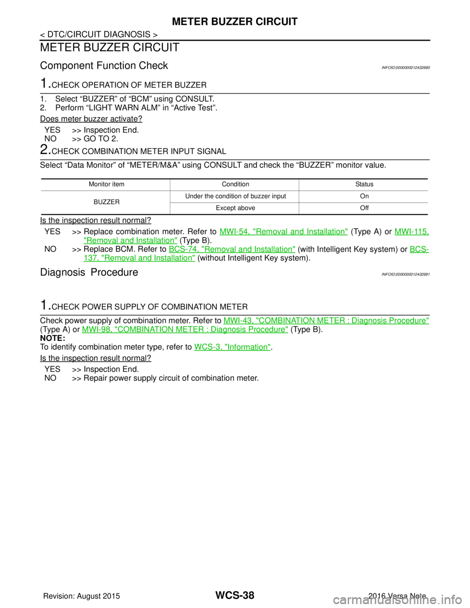
METER BUZZER CIRCUIT
METER BUZZER CIRCUIT
Component Function CheckINFOID:0000000012432690
1.CHECK OPERATION OF METER BUZZER
1. Select “BUZZER” of “BCM” using CONSULT.
2. Perform “LIGHT WARN ALM” in “Active Test”.
Does meter buzzer activate?
YES >> Inspection End.
NO >> GO TO 2.
2.CHECK COMBINATION METER INPUT SIGNAL
Select “Data Monitor” of “METER/M&A” using CONSULT and check the “BUZZER” monitor value.
Is the inspection result normal?
YES >> Replace combination meter. Refer to MWI-54, "Removal and Installation" (Type A) or MWI-115,
"Removal and Installation" (Type B).
NO >> Replace BCM. Refer to BCS-74, "
Removal and Installation" (with Intelligent Key system) or BCS-
137, "Removal and Installation" (without Intelligent Key system).
Diagnosis ProcedureINFOID:0000000012432691
1.CHECK POWER SUPPLY OF COMBINATION METER
Check power supply of combination meter. Refer to MWI-43, "
COMBINATION METER : Diagnosis Procedure"
(Type A) or MWI-98, "COMBINATION METER : Diagnosis Procedure" (Type B).
NOTE:
To identify combination meter type, refer to WCS-3, "
Information".
Is the inspection result normal?
YES >> Inspection End.
NO >> Repair power supply circuit of combination meter.
Monitor item Condition Status
BUZZER Under the condition of buzzer input
On
Except above Off
Revision: August 2015 2016 Versa Note
cardiagn.com
Page 3554 of 3641

WCS
SEAT BELT BUCKLE SWITCH SIGNAL CIRCUIT
WCS-39
< DTC/CIRCUIT DIAGNOSIS >
C
D E
F
G H
I
J
K L
M B A
O P
SEAT BELT BUCKLE SW ITCH SIGNAL CIRCUIT
TYPE A
TYPE A : DescriptionINFOID:0000000012432692
Transmits a seat belt buckle switch LH signal to the combination meter.
TYPE A : Component Function CheckINFOID:0000000012432693
1. CHECK COMBINATION METER INPUT SIGNAL
Select “Data Monitor” of “METER/M&A” using “C ONSULT” and check the “BUCKLE SW” monitor value.
Is the inspection result normal?
YES >> Inspection End.
NO >> Refer to WCS-39, "
TYPE A : DiagnosisProcedure".
TYPE A : Diagnosis ProcedureINFOID:0000000012432694
Regarding Wiring Diagram information, refer to WCS-26, "Wiring Diagram".
1.CHECK COMBINATION METER INPUT SIGNAL
1. Turn ignition switch ON.
2. Check voltage between combination meter harness connector M82 terminal 9 and ground.
Is the inspection result normal?
YES >> Replace combination meter. Refer to MWI-54, "Removal and Installation" (Type A).
NO >> GO TO 2.
2.CHECK SEAT BELT BUCKLE SWITCH LH CIRCUIT
1. Turn ignition switch OFF.
2. Disconnect combination meter harness connector M82 and seat belt buckle switch LH harness connector
B13.
3. Check continuity between combination meter har ness connector M82 terminal 9 and seat belt buckle
switch LH harness connector B13 terminal 1.
4. Check continuity between combination meter harness connector M82 terminal 9 and ground.
Is the inspection result normal?
Monitor item Condition Status
BUCKLE SW When seat belt LH is fastened
OFF
When seat belt LH is unfastened ON
Combination meter
GroundCondition Vo l ta g e
(Approx.)
Connector Terminal
M82 9— When seat belt LH is fastened
Battery voltage
When seat belt LH is unfastened 0 V
Combination meterSeat belt buckle switch LH
Continuity
Connector TerminalConnector Terminal
M82 9B13 1Yes
Combination meter GroundContinuity
Connector Terminal
M82 9— No
Revision: August 2015 2016 Versa Note
cardiagn.com
Page 3555 of 3641

WCS-40
< DTC/CIRCUIT DIAGNOSIS >
SEAT BELT BUCKLE SWITCH SIGNAL CIRCUIT
YES >> GO TO 3.
NO >> Repair or replace harness or connector.
3.CHECK SEAT BELT BUCKLE SWITCH LH GROUND CIRCUIT
Check continuity between seat belt buckle swit ch LH harness connector B13 terminal 2 and ground.
Is the inspection result normal?
YES >> Check the seat belt buckle switch LH. Refer to SR-35, "Removal and Installation".
NO >> Repair or replace harness or connector.
TYPE A : Component InspectionINFOID:0000000012432695
1. CHECK SEAT BELT BUCKLE SWITCH LH
1. Turn ignition switch OFF.
2. Disconnect the seat belt buckle switch LH.
3. Check continuity between the seat belt buckle switch LH terminals 1 and 2.
Is the inspection result normal?
YES >> Inspection End.
NO >> Replace the seat belt buckle switch LH. Refer to SR-35, "
Removal and Installation".
TYPE B
TYPE B : DescriptionINFOID:0000000012432696
Transmits a seat belt buckle switch LH signal to the combination meter.
TYPE B : Component Function CheckINFOID:0000000012432697
1. CHECK COMBINATION METER INPUT SIGNAL
Select “Data Monitor” of “METER/M&A” using “C ONSULT” and check the “BUCKLE SW” monitor value.
Is the inspection result normal?
YES >> Inspection End.
NO >> Refer to WCS-40, "
TYPE B : DiagnosisProcedure".
TYPE B : Diagnosis ProcedureINFOID:0000000012432698
Regarding Wiring Diagram information, refer to WCS-26, "Wiring Diagram".
1.CHECK COMBINATION METER INPUT SIGNAL
1. Turn ignition switch ON.
2. Check voltage between combination meter harness connector M24 terminal 9 and ground.
Seat belt buckle switch LH GroundContinuity
Connector Terminal
B13 2—Yes
Terminal ConditionContinuity
12 When seat belt is fastened
No
When seat belt is unfastened Yes
Monitor itemCondition Status
BUCKLE SW When seat belt LH is fastened
OFF
When seat belt LH is unfastened ON
Revision: August 2015 2016 Versa Note
cardiagn.com
Page 3556 of 3641

WCS
SEAT BELT BUCKLE SWITCH SIGNAL CIRCUIT
WCS-41
< DTC/CIRCUIT DIAGNOSIS >
C
D E
F
G H
I
J
K L
M B A
O P
Is the inspection result normal?
YES >> Replace combination meter. Refer to MWI-115, "Removal and Installation" (Type B).
NO >> GO TO 2.
2.CHECK SEAT BELT BUCKLE SWITCH LH CIRCUIT
1. Turn ignition switch OFF.
2. Disconnect combination meter harness connector M24 and seat belt buckle switch LH harness connector
B13.
3. Check continuity between combination meter har ness connector M24 terminal 9 and seat belt buckle
switch LH harness connector B13 terminal 1.
4. Check continuity between combination meter harness connector M24 terminal 9 and ground.
Is the inspection result normal?
YES >> GO TO 3.
NO >> Repair or replace harness or connector.
3.CHECK SEAT BELT BUCKLE SWITCH LH GROUND CIRCUIT
Check continuity between seat belt buckle swit ch LH harness connector B13 terminal 2 and ground.
Is the inspection result normal?
YES >> Check the seat belt buckle switch LH. Refer to SR-35, "Removal and Installation".
NO >> Repair or replace harness or connector.
TYPE B : Component InspectionINFOID:0000000012432699
1. CHECK SEAT BELT BUCKLE SWITCH LH
1. Turn ignition switch OFF.
2. Disconnect the seat belt buckle switch LH.
3. Check continuity between the seat belt buckle switch LH terminals 1 and 2.
Is the inspection result normal?
YES >> Inspection End.
NO >> Replace the seat belt buckle switch LH. Refer to SR-35, "
Removal and Installation".
Combination meter
GroundCondition Vo l ta g e
(Approx.)
Connector Terminal
M24 9— When seat belt LH is fastened
Battery voltage
When seat belt LH is unfastened 0 V
Combination meterSeat belt buckle switch LH
Continuity
Connector TerminalConnector Terminal
M24 9B13 1Yes
Combination meter GroundContinuity
Connector Terminal
M24 9— No
Seat belt buckle switch LH
GroundContinuity
Connector Terminal
B13 2—Yes
Terminal ConditionContinuity
12 When seat belt is fastened
No
When seat belt is unfastened Yes
Revision: August 2015 2016 Versa Note
cardiagn.com
Page 3557 of 3641

WCS-42
< DTC/CIRCUIT DIAGNOSIS >
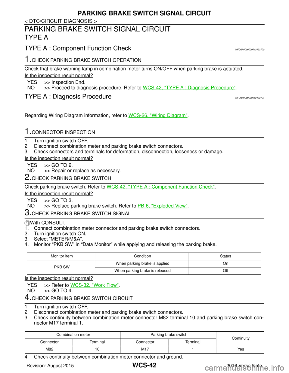
PARKING BRAKE SWITCH SIGNAL CIRCUIT
PARKING BRAKE SWITCH SIGNAL CIRCUIT
TYPE A
TYPE A : Component Function CheckINFOID:0000000012432700
1.CHECK PARKING BRAKE SWITCH OPERATION
Check that brake warning lamp in combination me ter turns ON/OFF when parking brake is actuated.
Is the inspection result normal?
YES >> Inspection End.
NO >> Proceed to diagnosis procedure. Refer to WCS-42, "
TYPE A : Diagnosis Procedure".
TYPE A : Diagnosis ProcedureINFOID:0000000012432701
Regarding Wiring Diagram information, refer to WCS-26, "Wiring Diagram".
1.CONNECTOR INSPECTION
1. Turn ignition switch OFF.
2. Disconnect combination meter and parking brake switch connectors.
3. Check connectors and terminals for deformation, disconnection, looseness or damage.
Is the inspection result normal?
YES >> GO TO 2.
NO >> Repair or replace as necessary.
2.CHECK PARKING BRAKE SWITCH
Check parking brake switch. Refer to WCS-42, "
TYPE A : Component Function Check".
Is the inspection result normal?
YES >> GO TO 3.
NO >> Replace parking brake switch. Refer to PB-6, "
Exploded View".
3.CHECK PARKING BRAKE SWITCH SIGNAL
With CONSULT.
1. Connect combination meter connector and parking brake switch connectors.
2. Turn ignition switch ON.
3. Select “METER/M&A”.
4. Monitor “PKB SW” in “Data Monitor” while applying and releasing the parking brake.
Is the inspection result normal?
YES >> Refer to WCS-32, "Work Flow".
NO >> GO TO 4.
4.CHECK PARKING BRAKE SWITCH CIRCUIT
1. Turn ignition switch OFF.
2. Disconnect combination meter and parking brake switch connectors.
3. Check continuity between combination meter connec tor M82 terminal 10 and parking brake switch con-
nector M17 terminal 1.
4. Check continuity between combination meter connector and ground.
Monitor item Condition Status
PKB SW When parking brake is applied
On
When parking brake is released Off
Combination meterParking brake switch
Continuity
Connector TerminalConnector Terminal
M82 10 M171Yes
Revision: August 2015 2016 Versa Note
cardiagn.com
Page 3558 of 3641

WCS
PARKING BRAKE SWITCH SIGNAL CIRCUITWCS-43
< DTC/CIRCUIT DIAGNOSIS >
C
DE
F
G H
I
J
K L
M B A
O P
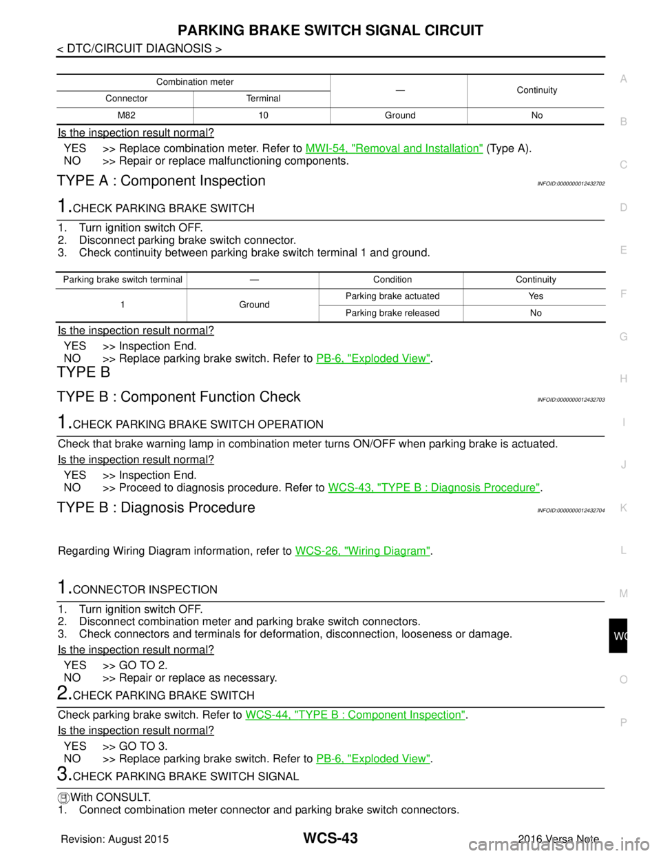
Is the inspection result normal?
YES >> Replace combination meter. Refer to MWI-54, "Removal and Installation" (Type A).
NO >> Repair or replace malfunctioning components.
TYPE A : Component InspectionINFOID:0000000012432702
1.CHECK PARKING BRAKE SWITCH
1. Turn ignition switch OFF.
2. Disconnect parking brake switch connector.
3. Check continuity between parking brake switch terminal 1 and ground.
Is the inspection result normal?
YES >> Inspection End.
NO >> Replace parking brake switch. Refer to PB-6, "
Exploded View".
TYPE B
TYPE B : Component Function CheckINFOID:0000000012432703
1.CHECK PARKING BRA KE SWITCH OPERATION
Check that brake warning lamp in combination meter turns ON/OFF when parking brake is actuated.
Is the inspection result normal?
YES >> Inspection End.
NO >> Proceed to diagnosis procedure. Refer to WCS-43, "
TYPE B : Diagnosis Procedure".
TYPE B : Diagnosis ProcedureINFOID:0000000012432704
Regarding Wiring Diagram information, refer to WCS-26, "Wiring Diagram".
1.CONNECTOR INSPECTION
1. Turn ignition switch OFF.
2. Disconnect combination meter and parking brake switch connectors.
3. Check connectors and terminals for deformation, disconnection, looseness or damage.
Is the inspection result normal?
YES >> GO TO 2.
NO >> Repair or replace as necessary.
2.CHECK PARKING BRAKE SWITCH
Check parking brake switch. Refer to WCS-44, "
TYPE B : Component Inspection".
Is the inspection result normal?
YES >> GO TO 3.
NO >> Replace parking brake switch. Refer to PB-6, "
Exploded View".
3.CHECK PARKING BRAKE SWITCH SIGNAL
With CONSULT.
1. Connect combination meter connector and parking brake switch connectors.
Combination meter —Continuity
Connector Terminal
M82 10 Ground No
Parking brake switch terminal —Condition Continuity
1 GroundParking brake actuated
Yes
Parking brake released No
Revision: August 2015 2016 Versa Note
cardiagn.com
Page 3559 of 3641

WCS-44
< DTC/CIRCUIT DIAGNOSIS >
PARKING BRAKE SWITCH SIGNAL CIRCUIT
2. Turn ignition switch ON.
3. Select “METER/M&A”.
4. Monitor “PKB SW” in “Data Monitor” while applying and releasing the parking brake.
Is the inspection result normal?
YES >> Refer to WCS-32, "Work Flow".
NO >> GO TO 4.
4.CHECK PARKING BRAKE SWITCH CIRCUIT
1. Turn ignition switch OFF.
2. Disconnect combination meter and parking brake switch connectors.
3. Check continuity between combination meter connec tor M24 terminal 10 and parking brake switch con-
nector M17 terminal 1.
4. Check continuity between combination meter connector and ground.
Is the inspection result normal?
YES >> Replace combination meter. Refer to MWI-115, "Removal and Installation" (Type B).
NO >> Repair or replace malfunctioning components.
TYPE B : Component InspectionINFOID:0000000012432705
1.CHECK PARKING BRAKE SWITCH
1. Turn ignition switch OFF.
2. Disconnect parking brake switch connector.
3. Check continuity between parki ng brake switch terminal 1 and ground.
Is the inspection result normal?
YES >> Inspection End.
NO >> Replace parking brake switch. Refer to PB-6, "
Exploded View".
Monitor itemCondition Status
PKB SW When parking brake is applied
ON
When parking brake is released OFF
Combination meterParking brake switch
Continuity
Connector TerminalConnector Terminal
M24 10 M171Yes
Combination meter
—Continuity
Connector Terminal
M24 10 Ground No
Parking brake switch terminal —Condition Continuity
1G ro u nd Parking brake actuated
Yes
Parking brake released No
Revision: August 2015 2016 Versa Note
cardiagn.com
Page 3560 of 3641

WCS
KEY SWITCH SIGNAL CIRCUIT (WITHOUT INTELLIGENT KEY)
WCS-45
< DTC/CIRCUIT DIAGNOSIS >
C
D E
F
G H
I
J
K L
M B A
O P
KEY SWITCH SIGNAL CIRCUIT (WITHOUT INTELLIGENT KEY)
DescriptionINFOID:0000000012432706
Transmits a key switch signal to the BCM.
Component Function CheckINFOID:0000000012432707
1. CHECK BCM INPUT SIGNAL
Select Data Monitor for BCM and check the KEY ON SW monitor value.
Is the inspection result normal?
YES >> Inspection End.
NO >> Refer to WCS-45, "
DiagnosisProcedure".
Diagnosis ProcedureINFOID:0000000012432708
Regarding Wiring Diagram information, refer to WCS-26, "Wiring Diagram".
1. CHECK FUSE
Check if the key switch 10A fuse [No. 8, located in the fuse block (J/B)] is blown.
Is the fuse blown?
YES >> Replace the fuse after repairing the affected circuit.
NO >> GO TO 2.
2. CHECK BCM INPUT SIGNAL
Check voltage between BCM harness connector M18 terminal 37 and ground.
Is the inspection result normal?
YES >> Inspection End.
NO >> GO TO 3.
3. CHECK KEY SWITCH CIRCUIT
1. Disconnect BCM connector M18 and key switch.
2. Check continuity between BCM harness connector M18 terminal 37 and key switch harness connector M27 terminal 1.
3. Check continuity between BCM harness connector M18 terminal 37 and ground.
Monitor Item Condition Status
KEY ON SW When key is removed from key cylinder
OFF
When key is inserted into key cylinder ON
Te r m i n a l s
ConditionVol tag e
(Approx.)
(+)
(−)
BCM
connector Te r m i n a l
M18 37Ground Key is inserted
Battery voltage
Key is removed 0V
BCM Key switch
Continuity
Connector TerminalConnector Terminal
M 183 7M 27 1 Y es
Revision: August 2015 2016 Versa Note
cardiagn.com