NISSAN NOTE 2016 Service Repair Manual
Manufacturer: NISSAN, Model Year: 2016, Model line: NOTE, Model: NISSAN NOTE 2016Pages: 3641, PDF Size: 28.72 MB
Page 3511 of 3641
DUCT AND GRILLEVTL-5
< REMOVAL AND INSTALLATION >
C
DE
F
G H
J
K L
M A
B
VTL
N
O P
REMOVAL AND INSTALLATION
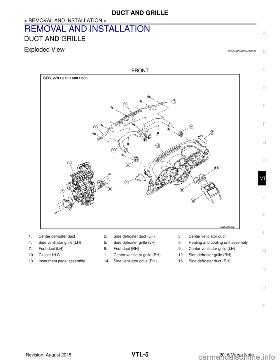
DUCT AND GRILLE
Exploded ViewINFOID:0000000012430549
FRONT
AWIIA1860ZZ
1. Center defroster duct 2. Side defroster duct (LH)3. Center ventilator duct
4. Side ventilator grille (LH) 5. Side defroster grille (LH)6. Heating and cooling unit assembly
7. Foot duct (LH) 8. Foot duct (RH)9. Center ventilator grille (LH)
10. Cluster lid C 11. Center ventilator grille (RH) 12. Side defroster grille (RH)
13. Instrument panel assembly 14. Side ventilator grille (RH) 15. Side defroster duct (RH)
Revision: August 2015 2016 Versa Note
cardiagn.com
Page 3512 of 3641
VTL-6
< REMOVAL AND INSTALLATION >
DUCT AND GRILLE
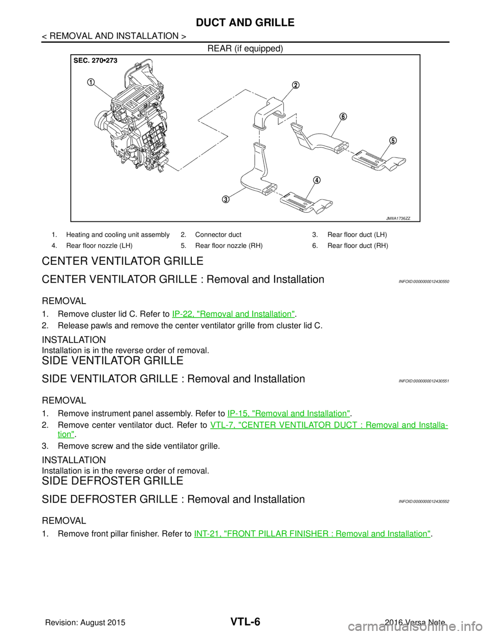
REAR (if equipped)
CENTER VENTILAT O R G R I L L E
CENTER VENTILATOR GRILLE : Removal and InstallationINFOID:0000000012430550
REMOVAL
1. Remove cluster lid C. Refer to IP-22, "Removal and Installation".
2. Release pawls and remove the center ventilator grille from cluster lid C.
INSTALLATION
Installation is in the reverse order of removal.
SIDE VENTILATOR GRILLE
SIDE VENTILATOR GRILLE : Removal and InstallationINFOID:0000000012430551
REMOVAL
1. Remove instrument panel assembly. Refer to IP-15, "Removal and Installation".
2. Remove center ventilator duct. Refer to VTL-7, "
CENTER VENTILATOR DUCT : Removal and Installa-
tion".
3. Remove screw and the side ventilator grille.
INSTALLATION
Installation is in the reverse order of removal.
SIDE DEFROSTER GRILLE
SIDE DEFROSTER GRILLE : Removal and InstallationINFOID:0000000012430552
REMOVAL
1. Remove front pillar finisher. Refer to INT-21, "FRONT PILLAR FINISHER : Removal and Installation".
JMIIA1736ZZ
1. Heating and cooling unit assembly 2. Connector duct 3. Rear floor duct (LH)
4. Rear floor nozzle (LH) 5. Rear floor nozzle (RH) 6. Rear floor duct (RH)
Revision: August 2015 2016 Versa Note
cardiagn.com
Page 3513 of 3641
DUCT AND GRILLEVTL-7
< REMOVAL AND INSTALLATION >
C
DE
F
G H
J
K L
M A
B
VTL
N
O P
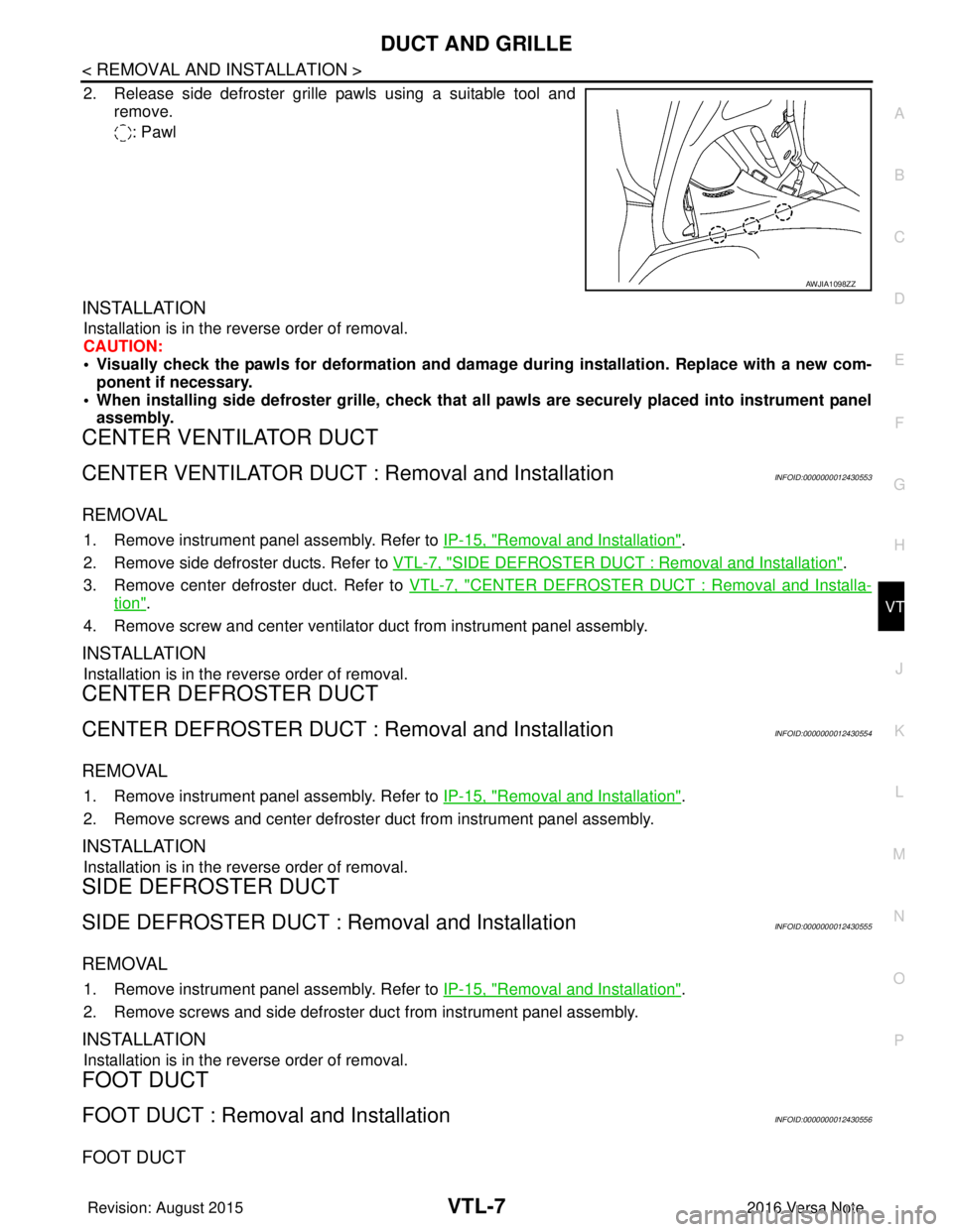
2. Release side defroster grille pawls using a suitable tool and remove.
: Pawl
INSTALLATION
Installation is in the reverse order of removal.
CAUTION:
• Visually check the pawls for deformation and dama ge during installation. Replace with a new com-
ponent if necessary.
• When installing side defroster grille, check that all pawls are securely placed into instrument panel assembly.
CENTER VENTILATOR DUCT
CENTER VENTILATOR DUCT : Removal and InstallationINFOID:0000000012430553
REMOVAL
1. Remove instrument panel assembly. Refer to IP-15, "Removal and Installation".
2. Remove side defroster ducts. Refer to VTL-7, "
SIDE DEFROSTER DUCT : Removal and Installation".
3. Remove center defroster duct. Refer to VTL-7, "
CENTER DEFROSTER DUCT : Removal and Installa-
tion".
4. Remove screw and center ventilator duct from instrument panel assembly.
INSTALLATION
Installation is in the reverse order of removal.
CENTER DEFROSTER DUCT
CENTER DEFROSTER DUCT : Removal and InstallationINFOID:0000000012430554
REMOVAL
1. Remove instrument panel assembly. Refer to IP-15, "Removal and Installation".
2. Remove screws and center defroster duct from instrument panel assembly.
INSTALLATION
Installation is in the reverse order of removal.
SIDE DEFROSTER DUCT
SIDE DEFROSTER DUCT : Removal and InstallationINFOID:0000000012430555
REMOVAL
1. Remove instrument panel assembly. Refer to IP-15, "Removal and Installation".
2. Remove screws and side defroster duct from instrument panel assembly.
INSTALLATION
Installation is in the reverse order of removal.
FOOT DUCT
FOOT DUCT : Removal and InstallationINFOID:0000000012430556
FOOT DUCT
AWJIA1098ZZ
Revision: August 2015 2016 Versa Note
cardiagn.com
Page 3514 of 3641
VTL-8
< REMOVAL AND INSTALLATION >
DUCT AND GRILLE
Removal
1. Remove instrument panel assembly. Refer to IP-15, "Removal and Installation".
2. Remove screws and foot duct (LH/RH) from heating and cooling unit assembly.
Installation
Installation is in the reverse order of removal.
REAR FLOOR DUCT
REAR FLOOR DUCT : Remo val and InstallationINFOID:0000000012430557
REMOVAL
1. Remove driver seat (if necessary). Refer to SE-20, "DRIVER SIDE : Removal and Installation".
2. Remove passenger seat (if necessary). Refer to SE-22, "
PASSENGER SIDE : Removal and Installation".
3. Remove rear seat cushion. Refer to SE-26, "
SEAT CUSHION : Removal and Installation".
4. Remove dash side finisher (LH/RH). Refer to INT-24, "
DASH SIDE FINISHER : Removal and Installation".
5. Remove center pillar lower finisher (LH/RH). Refer to INT-25, "
CENTER PILLAR LOWER FINISHER :
Removal and Installation".
6. Remove center console lower. Refer to IP-20, "
Removal and Installation"
7. Position floor trim and floor insulators aside.
8. Release and remove rear floor ducts.
INSTALLATION
Install in the reverse order of removal.
Revision: August 2015 2016 Versa Note
cardiagn.com
Page 3515 of 3641
FRONT BLOWER MOTORVTL-9
< REMOVAL AND INSTALLATION >
C
DE
F
G H
J
K L
M A
B
VTL
N
O P
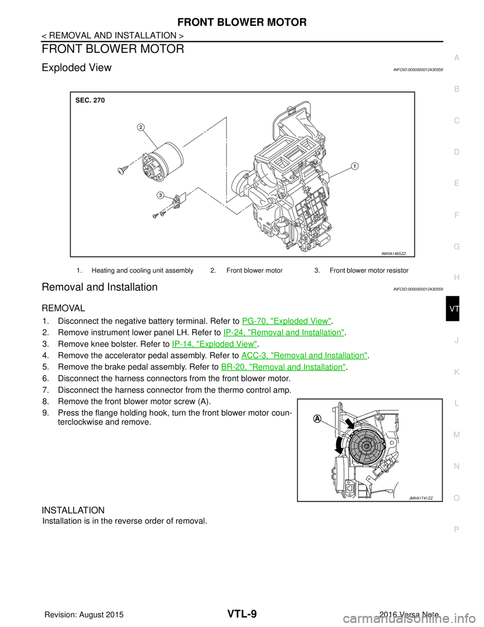
FRONT BLOWER MOTOR
Exploded ViewINFOID:0000000012430558
Removal and InstallationINFOID:0000000012430559
REMOVAL
1. Disconnect the negative battery terminal. Refer to PG-70, "Exploded View".
2. Remove instrument lower panel LH. Refer to IP-24, "
Removal and Installation".
3. Remove knee bolster. Refer to IP-14, "
Exploded View".
4. Remove the accelerator pedal assembly. Refer to ACC-3, "
Removal and Installation".
5. Remove the brake pedal assembly. Refer to BR-20, "
Removal and Installation".
6. Disconnect the harness connectors from the front blower motor.
7. Disconnect the harness connector from the thermo control amp.
8. Remove the front blower motor screw (A).
9. Press the flange holding hook, turn the front blower motor coun- terclockwise and remove.
INSTALLATION
Installation is in the reverse order of removal.
1. Heating and cooling unit assembly 2. Front blower motor 3. Front blower motor resistor
AWIIA1465ZZ
JMIIA1741ZZ
Revision: August 2015 2016 Versa Note
cardiagn.com
Page 3516 of 3641

WCS
WCS-1
DRIVER INFORMATION & MULTIMEDIA
C
DE
F
G H
I
J
K L
M B
SECTION WCS
A
O P
CONTENTS
WARNING CHIME SYSTEM
HOW TO USE THIS MANU AL ......................3
APPLICATION NOTICE ................................. .....3
Information .......................................................... ......3
PRECAUTION ...............................................4
PRECAUTIONS .............................................. .....4
Precaution for Supplemental Restraint System
(SRS) "AIR BAG" and "SEAT BELT PRE-TEN-
SIONER" ............................................................. ......
4
SYSTEM DESCRIPTION ..............................5
COMPONENT PARTS ................................... .....5
Component Parts Location .................................. ......5
Combination Meter ....................................................5
SYSTEM ..............................................................7
WARNING CHIME SYSTEM .......................................7
WARNING CHIME SYSTEM : System Description
......
7
WARNING CHIME SYSTEM : Fail-safe ....................8
LIGHT REMINDER WARNING CHIME ................. ......8
LIGHT REMINDER WARNING CHIME : Light Re-
minder Warning .........................................................
8
PARKING BRAKE RELEASE WARNING CHIME ......9
PARKING BRAKE RELEASE WARNING CHIME
: Parking Brake Release Warning Chime ............ ......
9
SEAT BELT REMINDER WARNING CHIME ........ ....10
SEAT BELT REMINDER WARNING CHIME :
Seat belt Warning ....................................................
10
KEY WARNING CHIME (WITHOUT INTELLIGENT
KEY) ....................................................................... ....
11
KEY WARNING CHIME (WITHOUT INTELLI-
GENT KEY) : Key Warning Chime ..........................
11
DIAGNOSIS SYSTEM (COMBINATION
METER) .............................................................
13
TYPE A ............................................ ...........................13
TYPE A : On Board Diagnosis Function .............. ....13
TYPE A : CONSULT Function (METER/M&A) ........14
TYPE B ............................................ ...........................16
TYPE B : On Board Diagnosis Function .............. ....16
TYPE B : CONSULT Function (METER/M&A) ........18
DIAGNOSIS SYSTEM (BCM) (WITH INTELLI-
GENT KEY SYSTEM) .......................................
21
COMMON ITEM ..................................................... ....21
COMMON ITEM : CONSULT Function (BCM -
COMMON ITEM) .....................................................
21
BUZZER ................................................................. ....22
BUZZER : CONSULT Function (BCM - BUZZER) ....22
DIAGNOSIS SYSTEM (BCM) (WITHOUT IN-
TELLIGENT KEY SYSTEM) .............................
23
COMMON ITEM ..................................................... ....23
COMMON ITEM : CONSULT Function (BCM -
COMMON ITEM) .....................................................
23
BUZZER ................................................................. ....24
BUZZER : CONSULT Function (BCM - BUZZER) ....24
ECU DIAGNOSIS INFORMATION ..............25
BCM, COMBINATION METER .........................25
List of ECU Reference ......................................... ....25
WIRING DIAGRAM ......................................26
WARNING CHIME SYSTEM .............................26
Wiring Diagram .................................................... ....26
BASIC INSPECTION ...................................32
DIAGNOSIS AND REPAIR WORK FLOW .......32
Revision: August 2015 2016 Versa Note
cardiagn.com
Page 3517 of 3641

WCS-2
Work Flow ...............................................................32
DTC/CIRCUIT DIAGNOSIS ...................... ...34
POWER SUPPLY AND GROUND CIRCUIT .. ...34
COMBINATION METER (TYPE A) ........................ ...34
COMBINATION METER (TYPE A) : Diagnosis
Procedure ............................................................ ...
34
COMBINATION METER (TYPE B) ........................ ...34
COMBINATION METER (TYPE B) : Diagnosis
Procedure ............................................................ ...
35
BCM (BODY CONTROL SYSTEM) (WITH INTEL-
LIGENT KEY SYSTEM) ..... .......................................
35
BCM (BODY CONTROL S YSTEM) (WITH INTEL-
LIGENT KEY SYSTEM) : Dia gnosis Procedure .....
35
BCM (BODY CONTROL SYST EM) (WITHOUT IN-
TELLIGENT KEY SYSTEM) . ....................................
36
BCM (BODY CONTROL SYSTEM) (WITHOUT
INTELLIGENT KEY SYSTEM) : Diagnosis Proce-
dure ..................................................................... ...
36
METER BUZZER CIRCUIT ................................38
Component Function Check ................................ ...38
Diagnosis Procedure .............................................38
SEAT BELT BUCKLE SWITCH SIGNAL CIR-
CUIT ...................................................................
39
TYPE A ................................................................... ...39
TYPE A : Description ..............................................39
TYPE A : Component Func tion Check ..................39
TYPE A : Diagnosis Procedu re ..............................39
TYPE A : Component Inspec tion ............................40
TYPE B ............... .................................................... ...40
TYPE B : Description ..............................................40
TYPE B : Component Func tion Check ..................40
TYPE B : Diagnosis Procedu re ..............................40
TYPE B : Component Inspec tion ............................41
PARKING BRAKE SWITCH SIGNAL CIR-
CUIT ................................................................ ...
42
TYPE A ............................................ ..........................42
TYPE A : Component Functi on Check ....................42
TYPE A : Diagnosis Procedur e ...............................42
TYPE A : Component Inspec tion ............................43
TYPE B ............ ................................ ..........................43
TYPE B : Component Functi on Check ....................43
TYPE B : Diagnosis Procedur e ...............................43
TYPE B : Component Inspec tion ............................44
KEY SWITCH SIGNAL CIRCUIT (WITHOUT
INTELLIGENT KEY) ....................................... ...
45
Description ........................................................... ...45
Component Function Check ..................................45
Diagnosis Procedure ..............................................45
Component Inspection ............................................46
SYMPTOM DIAGNOSIS ............................47
THE PARKING BRAKE RELEASE WARNING
CONTINUES SOUNDING, OR DOES NOT
SOUND ........................................................... ...
47
Description ........................................................... ...47
Diagnosis Procedure ...............................................47
THE SEAT BELT REMINDER WARNING
CONTINUES SOUNDING, OR DOES NOT
SOUND ..............................................................
48
Description ........................................................... ...48
Diagnosis Procedure ...............................................48
THE LIGHT REMINDER WARNING DOES
NOT SOUND ......................................................
49
Description ........................................................... ...49
Diagnosis Procedure ...............................................49
THE KEY WARNING DOES NOT SOUND
(WITHOUT INTELLIGENT KEY) .......................
50
Description ..............................................................50
Diagnosis Procedure ...............................................50
Revision: August 2015 2016 Versa Note
cardiagn.com
Page 3518 of 3641
WCS
APPLICATION NOTICEWCS-3
< HOW TO USE THIS MANUAL >
C
DE
F
G H
I
J
K L
M B A
O P
HOW TO USE THIS MANUAL
APPLICATION NOTICE
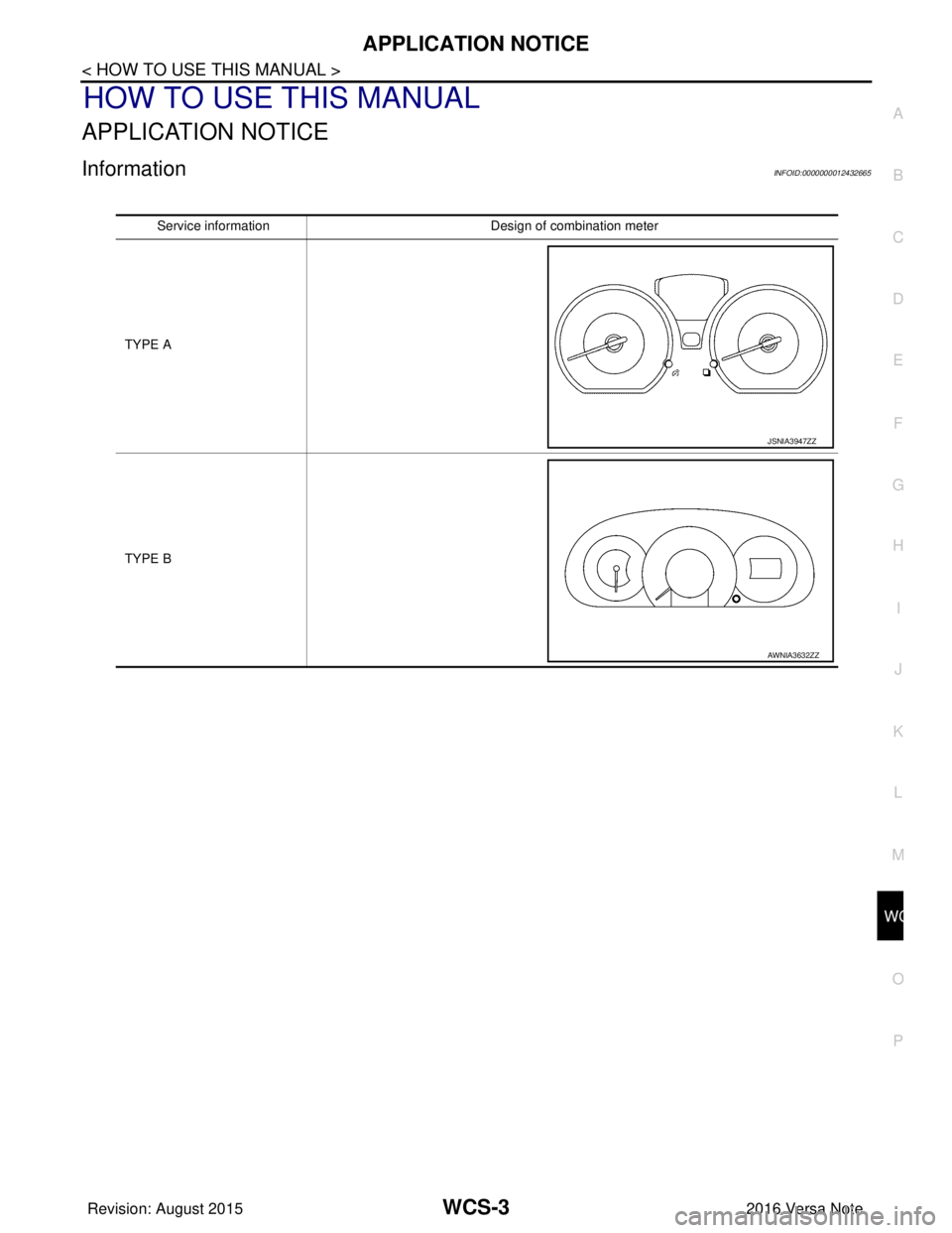
InformationINFOID:0000000012432665
Service information Design of combination meter
TYPE A
TYPE B
JSNIA3947ZZ
AWNIA3632ZZ
Revision: August 2015 2016 Versa Note
cardiagn.com
Page 3519 of 3641
WCS-4
< PRECAUTION >
PRECAUTIONS
PRECAUTION
PRECAUTIONS
Precaution for Supplemental Restraint System (SRS) "AIR BAG" and "SEAT BELT
PRE-TENSIONER"
INFOID:0000000012542981
The Supplemental Restraint System such as “A IR BAG” and “SEAT BELT PRE-TENSIONER”, used along
with a front seat belt, helps to reduce the risk or severity of injury to the driver and front passenger for certain
types of collision. Information necessary to service the system safely is included in the SR and SB section of
this Service Manual.
WARNING:
• To avoid rendering the SRS inopera tive, which could increase the risk of personal injury or death in
the event of a collision which would result in air bag inflation, all maintenance must be performed by
an authorized NISSAN/INFINITI dealer.
• Improper maintenance, including in correct removal and installation of the SRS, can lead to personal
injury caused by unintent ional activation of the system. For re moval of Spiral Cable and Air Bag
Module, see the SR section.
• Do not use electrical test equipmen t on any circuit related to the SRS unless instructed to in this
Service Manual. SRS wiring harn esses can be identified by yellow and/or orange harnesses or har-
ness connectors.
PRECAUTIONS WHEN USING POWER TOOLS (AIR OR ELECTRIC) AND HAMMERS
WARNING:
• When working near the Airbag Diagnosis Sensor Unit or other Airbag System sensors with the Igni-
tion ON or engine running, DO NOT use air or electri c power tools or strike near the sensor(s) with a
hammer. Heavy vibration could activate the sensor( s) and deploy the air bag(s), possibly causing
serious injury.
• When using air or electric power tools or hammers , always switch the Ignition OFF, disconnect the
battery and wait at least three minutes before performing any service.
Revision: August 2015 2016 Versa Note
cardiagn.com
Page 3520 of 3641
WCS
COMPONENT PARTSWCS-5
< SYSTEM DESCRIPTION >
C
DE
F
G H
I
J
K L
M B A
O P
SYSTEM DESCRIPTION
COMPONENT PARTS
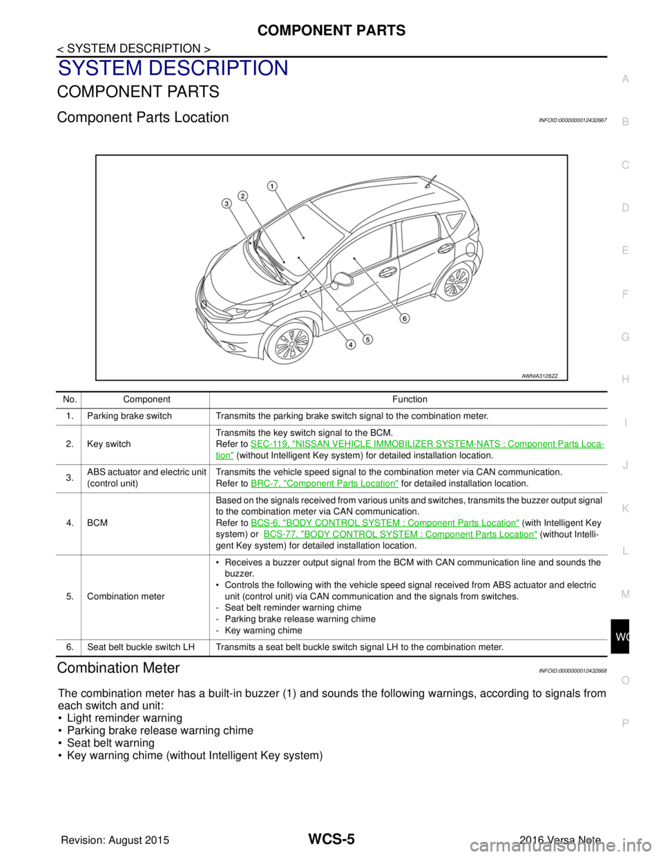
Component Parts LocationINFOID:0000000012432667
Combination MeterINFOID:0000000012432668
The combination meter has a built-in buzzer (1) and sounds the following warnings, according to signals from
each switch and unit:
• Light reminder warning
• Parking brake release warning chime
• Seat belt warning
• Key warning chime (without Intelligent Key system)
AWNIA3128ZZ
No. Component Function
1. Parking brake switch Transmits the parking brake switch signal to the combination meter.
2. Key switch Transmits the key switch signal to the BCM.
Refer to
SEC-119, "
NISSAN VEHICLE IMMOBILIZER SYSTEM -NATS : Component Parts Loca-
tion" (without Intelligent Key system) for detailed installation location.
3. ABS actuator and electric unit
(control unit) Transmits the vehicle speed signal to the combination meter via CAN communication.
Refer to BRC-7, "
Component Parts Location" for detailed installation location.
4. BCM Based on the signals received from various units and switches, transmits the buzzer output signal
to the combination meter via CAN communication.
Refer to BCS-6, "
BODY CONTROL SYSTEM : Co
mponent Parts Location" (with Intelligent Key
system) or BCS-77, "
BODY CONTROL SYSTEM : Component Parts Location" (without Intelli-
gent Key system) for detailed installation location.
5. Combination meter • Receives a buzzer output signal from the BCM with CAN communication line and sounds the
buzzer.
• Controls the following with the vehicle speed signal received from ABS actuator and electric
unit (control unit) via CAN communication and the signals from switches.
- Seat belt reminder warning chime
- Parking brake release warning chime
- Key warning chime
6. Seat belt buckle switch LH Transmits a seat belt buckle switch signal LH to the combination meter.
Revision: August 2015 2016 Versa Note
cardiagn.com