NISSAN PATROL 2000 Electronic Repair Manual
Manufacturer: NISSAN, Model Year: 2000, Model line: PATROL, Model: NISSAN PATROL 2000Pages: 1033, PDF Size: 30.71 MB
Page 821 of 1033
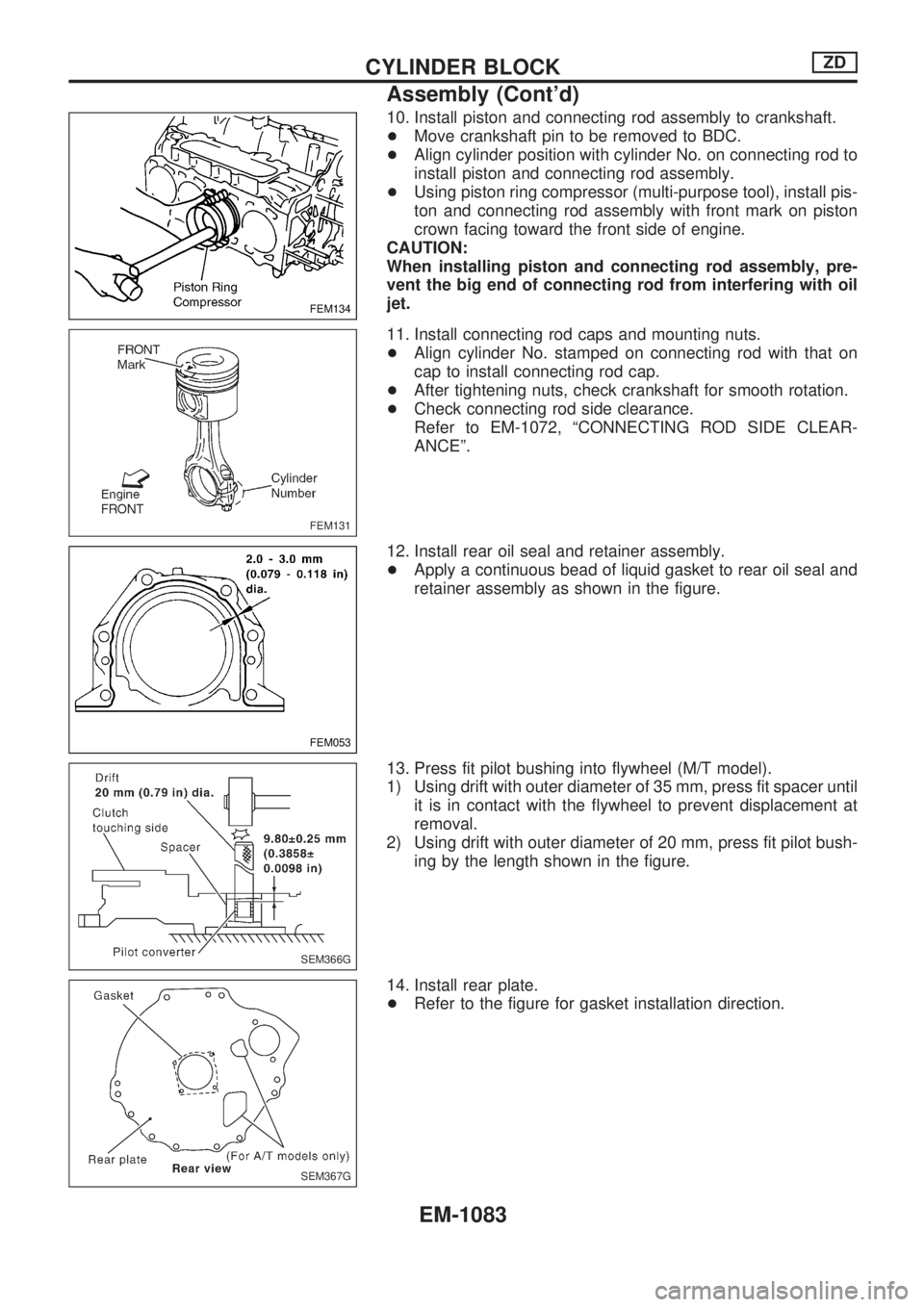
10. Install piston and connecting rod assembly to crankshaft.
+Move crankshaft pin to be removed to BDC.
+Align cylinder position with cylinder No. on connecting rod to
install piston and connecting rod assembly.
+Using piston ring compressor (multi-purpose tool), install pis-
ton and connecting rod assembly with front mark on piston
crown facing toward the front side of engine.
CAUTION:
When installing piston and connecting rod assembly, pre-
vent the big end of connecting rod from interfering with oil
jet.
11. Install connecting rod caps and mounting nuts.
+Align cylinder No. stamped on connecting rod with that on
cap to install connecting rod cap.
+After tightening nuts, check crankshaft for smooth rotation.
+Check connecting rod side clearance.
Refer to EM-1072, ªCONNECTING ROD SIDE CLEAR-
ANCEº.
12. Install rear oil seal and retainer assembly.
+Apply a continuous bead of liquid gasket to rear oil seal and
retainer assembly as shown in the figure.
13. Press fit pilot bushing into flywheel (M/T model).
1) Using drift with outer diameter of 35 mm, press fit spacer until
it is in contact with the flywheel to prevent displacement at
removal.
2) Using drift with outer diameter of 20 mm, press fit pilot bush-
ing by the length shown in the figure.
14. Install rear plate.
+Refer to the figure for gasket installation direction.
FEM134
FEM131
FEM053
SEM366G
SEM367G
CYLINDER BLOCKZD
Assembly (Cont'd)
EM-1083
Page 822 of 1033
15. Install removed parts to engine in the reverse order of disas-
sembly.
16. Remove engine from engine stand.
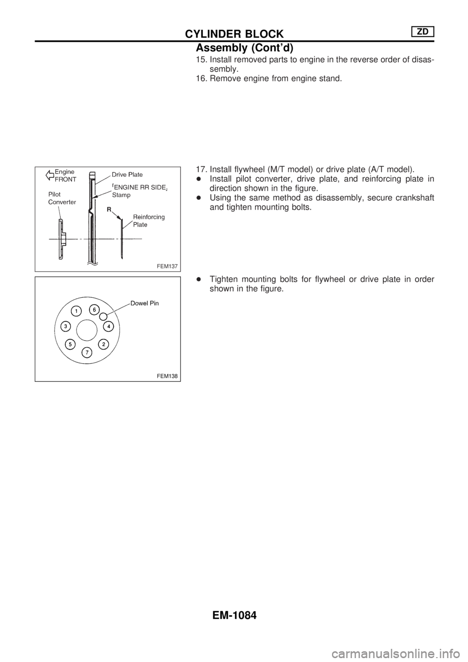
17. Install flywheel (M/T model) or drive plate (A/T model).
+Install pilot converter, drive plate, and reinforcing plate in
direction shown in the figure.
+Using the same method as disassembly, secure crankshaft
and tighten mounting bolts.
+Tighten mounting bolts for flywheel or drive plate in order
shown in the figure.
FEM137
FEM138
CYLINDER BLOCKZD
Assembly (Cont'd)
EM-1084
Page 823 of 1033
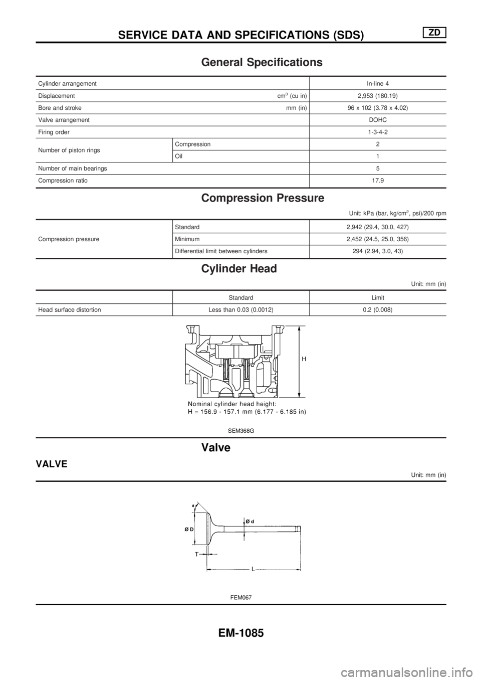
General Specifications
Cylinder arrangementIn-line 4
Displacementcm
3(cu in) 2,953 (180.19)
Bore and strokemm (in) 96 x 102 (3.78 x 4.02)
Valve arrangementDOHC
Firing order1-3-4-2
Number of piston ringsCompression 2
Oil1
Number of main bearings5
Compression ratio17.9
Compression Pressure
Unit: kPa (bar, kg/cm2, psi)/200 rpm
Compression pressureStandard 2,942 (29.4, 30.0, 427)
Minimum 2,452 (24.5, 25.0, 356)
Differential limit between cylinders 294 (2.94, 3.0, 43)
Cylinder Head
Unit: mm (in)
Standard Limit
Head surface distortion Less than 0.03 (0.0012) 0.2 (0.008)
SEM368G
Valve
VALVE
Unit: mm (in)
FEM067
SERVICE DATA AND SPECIFICATIONS (SDS)ZD
EM-1085
Page 824 of 1033
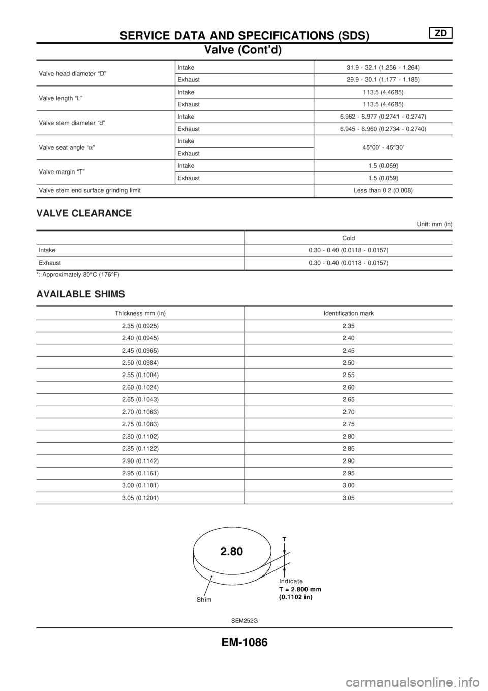
Valve head diameter ªDºIntake 31.9 - 32.1 (1.256 - 1.264)
Exhaust 29.9 - 30.1 (1.177 - 1.185)
Valve length ªLºIntake 113.5 (4.4685)
Exhaust 113.5 (4.4685)
Valve stem diameter ªdºIntake 6.962 - 6.977 (0.2741 - 0.2747)
Exhaust 6.945 - 6.960 (0.2734 - 0.2740)
Valve seat angle ªaºIntake
45É00¢- 45É30¢
Exhaust
Valve margin ªTºIntake 1.5 (0.059)
Exhaust 1.5 (0.059)
Valve stem end surface grinding limitLess than 0.2 (0.008)
VALVE CLEARANCE
Unit: mm (in)
Cold
Intake0.30 - 0.40 (0.0118 - 0.0157)
Exhaust0.30 - 0.40 (0.0118 - 0.0157)
*: Approximately 80ÉC (176ÉF)
AVAILABLE SHIMS
Thickness mm (in) Identification mark
2.35 (0.0925) 2.35
2.40 (0.0945) 2.40
2.45 (0.0965) 2.45
2.50 (0.0984) 2.50
2.55 (0.1004) 2.55
2.60 (0.1024) 2.60
2.65 (0.1043) 2.65
2.70 (0.1063) 2.70
2.75 (0.1083) 2.75
2.80 (0.1102) 2.80
2.85 (0.1122) 2.85
2.90 (0.1142) 2.90
2.95 (0.1161) 2.95
3.00 (0.1181) 3.00
3.05 (0.1201) 3.05
SEM252G
SERVICE DATA AND SPECIFICATIONS (SDS)ZD
Valve (Cont'd)
EM-1086
Page 825 of 1033
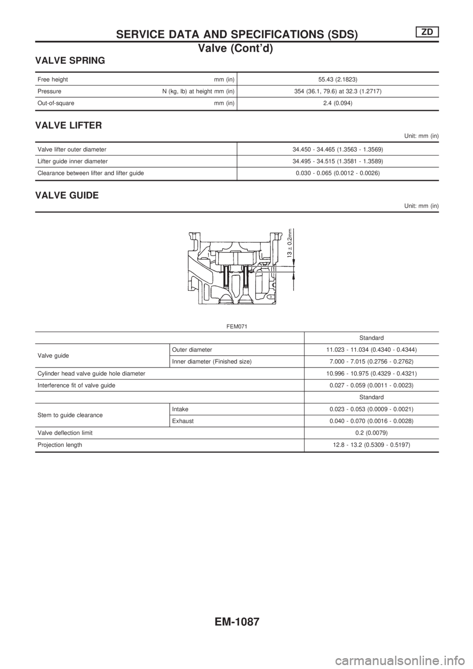
VALVE SPRING
Free height mm (in) 55.43 (2.1823)
Pressure N (kg, lb) at height mm (in) 354 (36.1, 79.6) at 32.3 (1.2717)
Out-of-square mm (in) 2.4 (0.094)
VALVE LIFTER
Unit: mm (in)
Valve lifter outer diameter 34.450 - 34.465 (1.3563 - 1.3569)
Lifter guide inner diameter 34.495 - 34.515 (1.3581 - 1.3589)
Clearance between lifter and lifter guide 0.030 - 0.065 (0.0012 - 0.0026)
VALVE GUIDE
Unit: mm (in)
FEM071
Standard
Valve guideOuter diameter 11.023 - 11.034 (0.4340 - 0.4344)
Inner diameter (Finished size) 7.000 - 7.015 (0.2756 - 0.2762)
Cylinder head valve guide hole diameter 10.996 - 10.975 (0.4329 - 0.4321)
Interference fit of valve guide0.027 - 0.059 (0.0011 - 0.0023)
Standard
Stem to guide clearanceIntake 0.023 - 0.053 (0.0009 - 0.0021)
Exhaust 0.040 - 0.070 (0.0016 - 0.0028)
Valve deflection limit0.2 (0.0079)
Projection length12.8 - 13.2 (0.5309 - 0.5197)
SERVICE DATA AND SPECIFICATIONS (SDS)ZD
Valve (Cont'd)
EM-1087
Page 826 of 1033
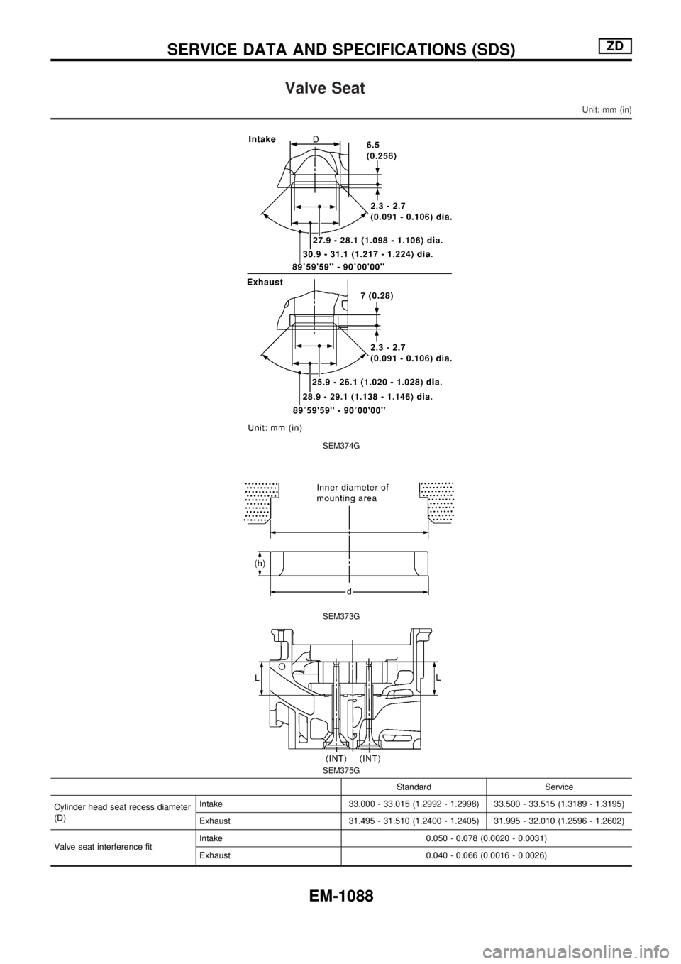
Valve Seat
Unit: mm (in)
SEM374G
SEM373G
SEM375G
Standard Service
Cylinder head seat recess diameter
(D)Intake 33.000 - 33.015 (1.2992 - 1.2998) 33.500 - 33.515 (1.3189 - 1.3195)
Exhaust 31.495 - 31.510 (1.2400 - 1.2405) 31.995 - 32.010 (1.2596 - 1.2602)
Valve seat interference fitIntake 0.050 - 0.078 (0.0020 - 0.0031)
Exhaust 0.040 - 0.066 (0.0016 - 0.0026)
SERVICE DATA AND SPECIFICATIONS (SDS)ZD
EM-1088
Page 827 of 1033
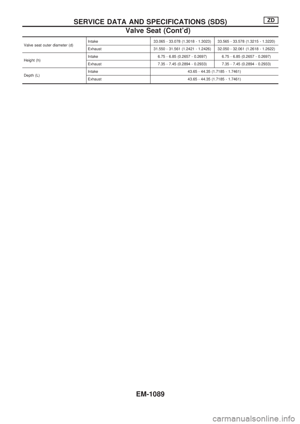
Valve seat outer diameter (d)Intake 33.065 - 33.078 (1.3018 - 1.3023) 33.565 - 33.578 (1.3215 - 1.3220)
Exhaust 31.550 - 31.561 (1.2421 - 1.2426) 32.050 - 32.061 (1.2618 - 1.2622)
Height (h)Intake 6.75 - 6.85 (0.2657 - 0.2697) 6.75 - 6.85 (0.2657 - 0.2697)
Exhaust 7.35 - 7.45 (0.2894 - 0.2933) 7.35 - 7.45 (0.2894 - 0.2933)
Depth (L)Intake 43.65 - 44.35 (1.7185 - 1.7461)
Exhaust 43.65 - 44.35 (1.7185 - 1.7461)
SERVICE DATA AND SPECIFICATIONS (SDS)ZD
Valve Seat (Cont'd)
EM-1089
Page 828 of 1033
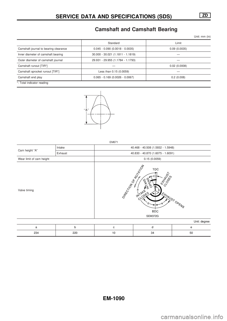
Camshaft and Camshaft Bearing
Unit: mm (in)
Standard Limit
Camshaft journal to bearing clearance 0.045 - 0.090 (0.0018 - 0.0035) 0.09 (0.0035)
Inner diameter of camshaft bearing 30.000 - 30.021 (1.1811 - 1.1819) Ð
Outer diameter of camshaft journal 29.931 - 29.955 (1.1784 - 1.1793) Ð
Camshaft runout [TIR*] Ð 0.02 (0.0008)
Camshaft sprocket runout [TIR*] Less than 0.15 (0.0059) Ð
Camshaft end play 0.065 - 0.169 (0.0026 - 0.0067) 0.2 (0.008)
*: Total indicator reading
EM671
Cam height ªAºIntake 40.468 - 40.508 (1.5932 - 1.5948)
Exhaust 40.830 - 40.870 (1.6075 - 1.6091)
Wear limit of cam height0.15 (0.0059)
Valve timing
SEM372G
Unit: degree
abcde
234 220 10 34 50
SERVICE DATA AND SPECIFICATIONS (SDS)ZD
EM-1090
Page 829 of 1033
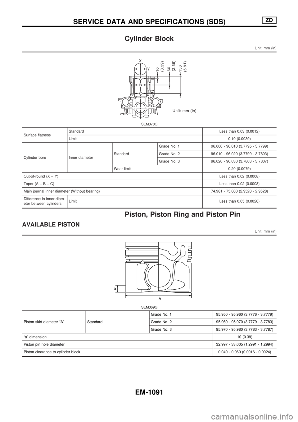
Cylinder Block
Unit: mm (in)
SEM370G
Surface flatnessStandardLess than 0.03 (0.0012)
Limit0.10 (0.0039)
Cylinder bore Inner diameterStandardGrade No. 1 96.000 - 96.010 (3.7795 - 3.7799)
Grade No. 2 96.010 - 96.020 (3.7799 - 3.7803)
Grade No. 3 96.020 - 96.030 (3.7803 - 3.7807)
Wear limit 0.20 (0.0079)
Out-of-round (X þ Y)Less than 0.02 (0.0008)
Taper (AþBþC)Less than 0.02 (0.0008)
Main journal inner diameter (Without bearing) 74.981 - 75.000 (2.9520 - 2.9528)
Difference in inner diam-
eter between cylindersLimitLess than 0.05 (0.0020)
Piston, Piston Ring and Piston Pin
AVAILABLE PISTON
Unit: mm (in)
SEM369G
Piston skirt diameter ªAº StandardGrade No. 1 95.950 - 95.960 (3.7776 - 3.7779)
Grade No. 2 95.960 - 95.970 (3.7779 - 3.7783)
Grade No. 3 95.970 - 95.980 (3.7783 - 3.7787)
ªaº dimension10 (0.39)
Piston pin hole diameter32.997 - 33.005 (1.2991 - 1.2994)
Piston clearance to cylinder block0.040 - 0.060 (0.0016 - 0.0024)
SERVICE DATA AND SPECIFICATIONS (SDS)ZD
EM-1091
Page 830 of 1033
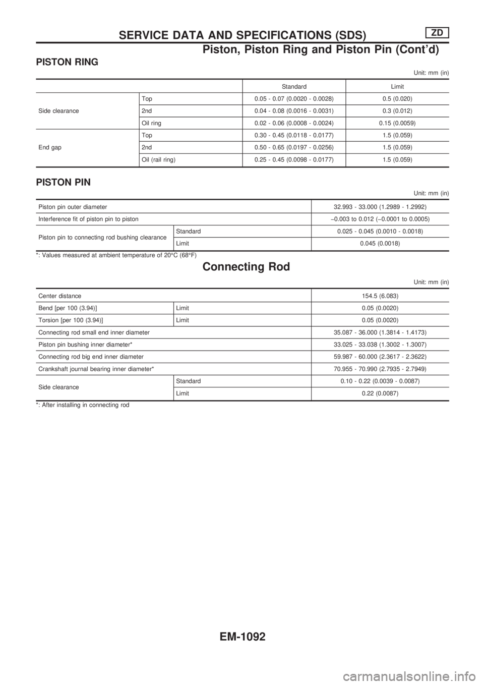
PISTON RING
Unit: mm (in)
Standard Limit
Side clearanceTop 0.05 - 0.07 (0.0020 - 0.0028) 0.5 (0.020)
2nd 0.04 - 0.08 (0.0016 - 0.0031) 0.3 (0.012)
Oil ring 0.02 - 0.06 (0.0008 - 0.0024) 0.15 (0.0059)
End gapTop 0.30 - 0.45 (0.0118 - 0.0177) 1.5 (0.059)
2nd 0.50 - 0.65 (0.0197 - 0.0256) 1.5 (0.059)
Oil (rail ring) 0.25 - 0.45 (0.0098 - 0.0177) 1.5 (0.059)
PISTON PIN
Unit: mm (in)
Piston pin outer diameter32.993 - 33.000 (1.2989 - 1.2992)
Interference fit of piston pin to piston þ0.003 to 0.012 (þ0.0001 to 0.0005)
Piston pin to connecting rod bushing clearanceStandard 0.025 - 0.045 (0.0010 - 0.0018)
Limit 0.045 (0.0018)
*: Values measured at ambient temperature of 20ÉC (68ÉF)
Connecting Rod
Unit: mm (in)
Center distance154.5 (6.083)
Bend [per 100 (3.94)] Limit 0.05 (0.0020)
Torsion [per 100 (3.94)] Limit 0.05 (0.0020)
Connecting rod small end inner diameter 35.087 - 36.000 (1.3814 - 1.4173)
Piston pin bushing inner diameter*33.025 - 33.038 (1.3002 - 1.3007)
Connecting rod big end inner diameter 59.987 - 60.000 (2.3617 - 2.3622)
Crankshaft journal bearing inner diameter* 70.955 - 70.990 (2.7935 - 2.7949)
Side clearanceStandard 0.10 - 0.22 (0.0039 - 0.0087)
Limit 0.22 (0.0087)
*: After installing in connecting rod
SERVICE DATA AND SPECIFICATIONS (SDS)ZD
Piston, Piston Ring and Piston Pin (Cont'd)
EM-1092