NISSAN PICK-UP 1998 Repair Manual
PICK-UP 1998
NISSAN
NISSAN
https://www.carmanualsonline.info/img/5/57374/w960_57374-0.png
NISSAN PICK-UP 1998 Repair Manual
Trending: engine oil, spare tire, heater, coolant capacity, jump cable, engine oil capacity, instrument cluster
Page 1211 of 1659
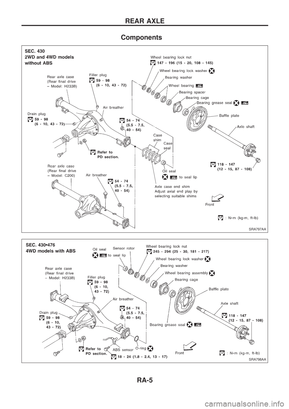
Components
SRA797AA
SRA798AA
REAR AXLE
RA-5
Page 1212 of 1659
Removal
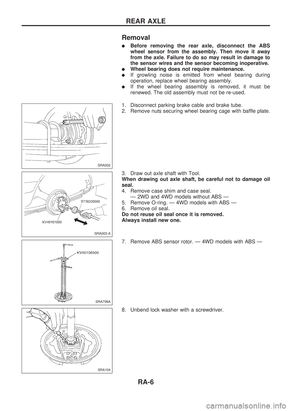
lBefore removing the rear axle, disconnect the ABS
wheel sensor from the assembly. Then move it away
from the axle. Failure to do so may result in damage to
the sensor wires and the sensor becoming inoperative.
lWheel bearing does not require maintenance.
lIf growling noise is emitted from wheel bearing during
operation, replace wheel bearing assembly.
lIf the wheel bearing assembly is removed, it must be
renewed. The old assembly must not be re-used.
1. Disconnect parking brake cable and brake tube.
2. Remove nuts securing wheel bearing cage with baffle plate.
3. Draw out axle shaft with Tool.
When drawing out axle shaft, be careful not to damage oil
seal.
4. Remove case shim and case seal.
Ð 2WD and 4WD models without ABS Ð
5. Remove O-ring. Ð 4WD models with ABS Ð
6. Remove oil seal.
Do not reuse oil seal once it is removed.
Always install new one.
7. Remove ABS sensor rotor. Ð 4WD models with ABS Ð
8. Unbend lock washer with a screwdriver.
SRA002
SRA003-A
SRA799A
SRA104
REAR AXLE
RA-6
Page 1213 of 1659
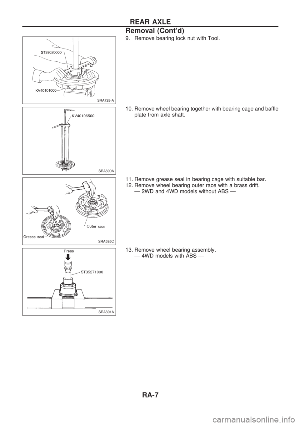
9. Remove bearing lock nut with Tool.
10. Remove wheel bearing together with bearing cage and baffle
plate from axle shaft.
11. Remove grease seal in bearing cage with suitable bar.
12. Remove wheel bearing outer race with a brass drift.
Ð 2WD and 4WD models without ABS Ð
13. Remove wheel bearing assembly.
Ð 4WD models with ABS Ð
SRA728-A
SRA800A
SRA595C
SRA801A
REAR AXLE
Removal (Cont'd)
RA-7
Page 1214 of 1659
Inspection
AXLE SHAFT
lCheck axle shaft for straightness, cracks, damage, wear or
distortion. Replace if necessary.
WHEEL BEARING
lMake sure wheel bearing rolls freely and is free from noise,
cracks, pitting or wear.
AXLE CASE
lCheck axle case for yield, deformation or cracks. Replace if
necessary.
Installation Ð 2WD and 4WD models without
ABS Ð
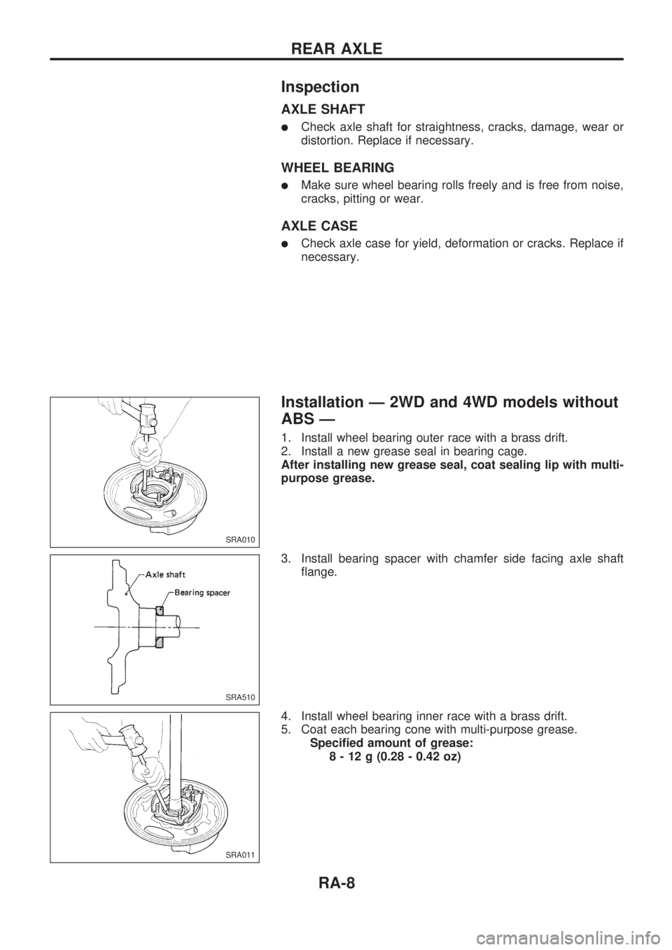
1. Install wheel bearing outer race with a brass drift.
2. Install a new grease seal in bearing cage.
After installing new grease seal, coat sealing lip with multi-
purpose grease.
3. Install bearing spacer with chamfer side facing axle shaft
flange.
4. Install wheel bearing inner race with a brass drift.
5. Coat each bearing cone with multi-purpose grease.
Specified amount of grease:
8 - 12 g (0.28 - 0.42 oz)
SRA010
SRA510
SRA011
REAR AXLE
RA-8
Page 1215 of 1659
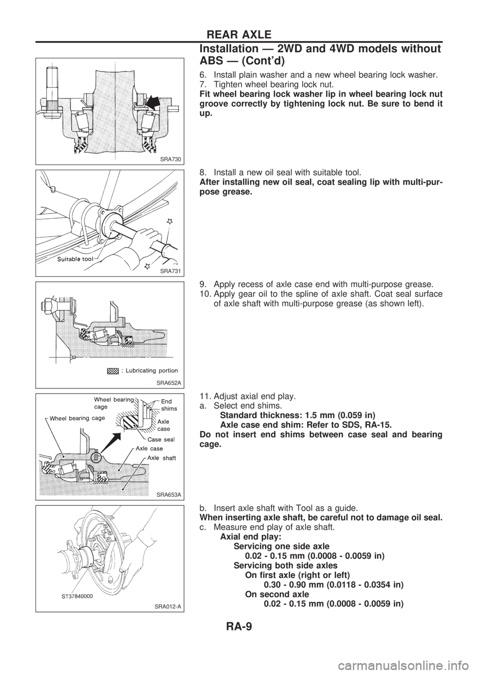
6. Install plain washer and a new wheel bearing lock washer.
7. Tighten wheel bearing lock nut.
Fit wheel bearing lock washer lip in wheel bearing lock nut
groove correctly by tightening lock nut. Be sure to bend it
up.
8. Install a new oil seal with suitable tool.
After installing new oil seal, coat sealing lip with multi-pur-
pose grease.
9. Apply recess of axle case end with multi-purpose grease.
10. Apply gear oil to the spline of axle shaft. Coat seal surface
of axle shaft with multi-purpose grease (as shown left).
11. Adjust axial end play.
a. Select end shims.
Standard thickness: 1.5 mm (0.059 in)
Axle case end shim: Refer to SDS, RA-15.
Do not insert end shims between case seal and bearing
cage.
b. Insert axle shaft with Tool as a guide.
When inserting axle shaft, be careful not to damage oil seal.
c. Measure end play of axle shaft.
Axial end play:
Servicing one side axle
0.02 - 0.15 mm (0.0008 - 0.0059 in)
Servicing both side axles
On first axle (right or left)
0.30 - 0.90 mm (0.0118 - 0.0354 in)
On second axle
0.02 - 0.15 mm (0.0008 - 0.0059 in)
SRA730
SRA731
SRA652A
SRA653A
SRA012-A
REAR AXLE
Installation Ð 2WD and 4WD models without
ABS Ð (Cont'd)
RA-9
Page 1216 of 1659
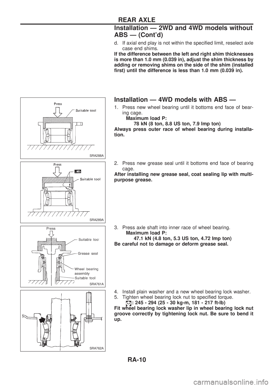
d. If axial end play is not within the specified limit, reselect axle
case end shims.
If the difference between the left and right shim thicknesses
is more than 1.0 mm (0.039 in), adjust the shim thickness by
adding or removing shims on the side of the shim (installed
first) until the difference is less than 1.0 mm (0.039 in).
Installation Ð 4WD models with ABS Ð
1. Press new wheel bearing until it bottoms end face of bear-
ing cage.
Maximum load P:
78 kN (8 ton, 8.8 US ton, 7.9 Imp ton)
Always press outer race of wheel bearing during installa-
tion.
2. Press new grease seal until it bottoms end face of bearing
cage.
After installing new grease seal, coat sealing lip with multi-
purpose grease.
3. Press axle shaft into inner race of wheel bearing.
Maximum load P:
47.1 kN (4.8 ton, 5.3 US ton, 4.72 Imp ton)
Be careful not to damage or deform grease seal.
4. Install plain washer and a new wheel bearing lock washer.
5. Tighten wheel bearing lock nut to specified torque.
: 245 - 294 (25 - 30 kg-m, 181 - 217 ft-lb)
Fit wheel bearing lock washer lip in wheel bearing lock nut
groove correctly by tightening lock nut. Be sure to bend it
up.
SRA288A
SRA289A
SRA761A
SRA762A
REAR AXLE
Installation Ð 2WD and 4WD models without
ABS Ð (Cont'd)
RA-10
Page 1217 of 1659
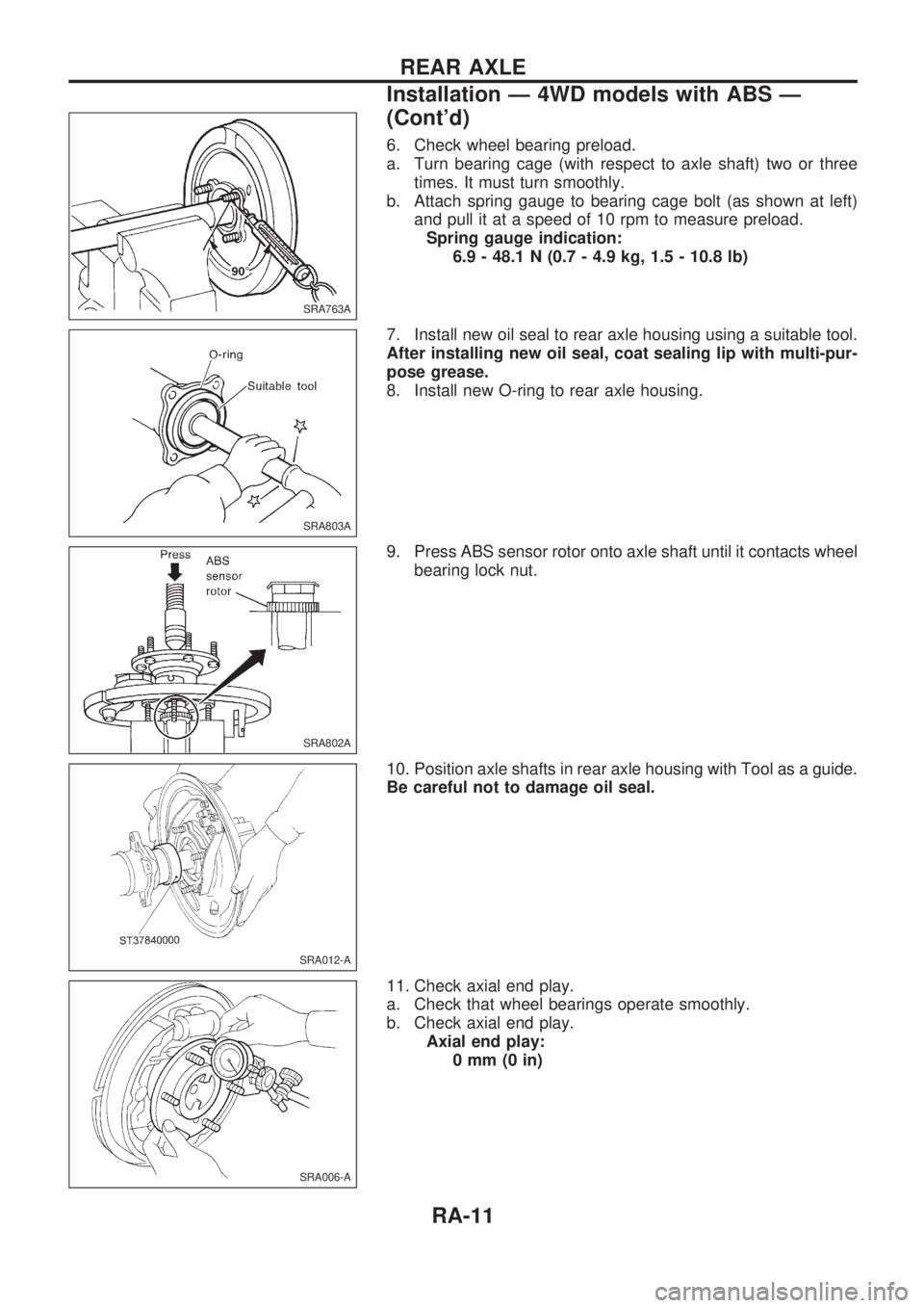
6. Check wheel bearing preload.
a. Turn bearing cage (with respect to axle shaft) two or three
times. It must turn smoothly.
b. Attach spring gauge to bearing cage bolt (as shown at left)
and pull it at a speed of 10 rpm to measure preload.
Spring gauge indication:
6.9 - 48.1 N (0.7 - 4.9 kg, 1.5 - 10.8 lb)
7. Install new oil seal to rear axle housing using a suitable tool.
After installing new oil seal, coat sealing lip with multi-pur-
pose grease.
8. Install new O-ring to rear axle housing.
9. Press ABS sensor rotor onto axle shaft until it contacts wheel
bearing lock nut.
10. Position axle shafts in rear axle housing with Tool as a guide.
Be careful not to damage oil seal.
11. Check axial end play.
a. Check that wheel bearings operate smoothly.
b. Check axial end play.
Axial end play:
0mm(0in)
SRA763A
SRA803A
SRA802A
SRA012-A
SRA006-A
REAR AXLE
Installation Ð 4WD models with ABS Ð
(Cont'd)
RA-11
Page 1218 of 1659
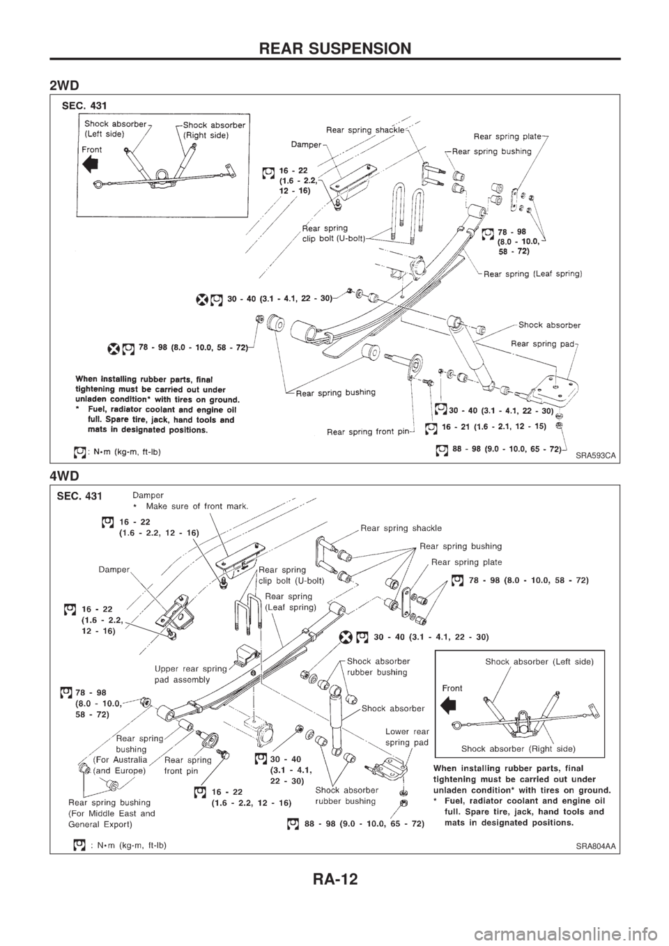
2WD
4WD
SRA593CA
SRA804AA
REAR SUSPENSION
RA-12
Page 1219 of 1659
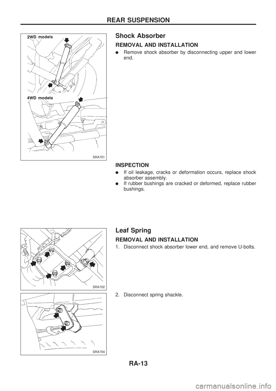
Shock Absorber
REMOVAL AND INSTALLATION
lRemove shock absorber by disconnecting upper and lower
end.
INSPECTION
lIf oil leakage, cracks or deformation occurs, replace shock
absorber assembly.
lIf rubber bushings are cracked or deformed, replace rubber
bushings.
Leaf Spring
REMOVAL AND INSTALLATION
1. Disconnect shock absorber lower end, and remove U-bolts.
2. Disconnect spring shackle.
SRA701
SRA702
SRA704
REAR SUSPENSION
RA-13
Page 1220 of 1659
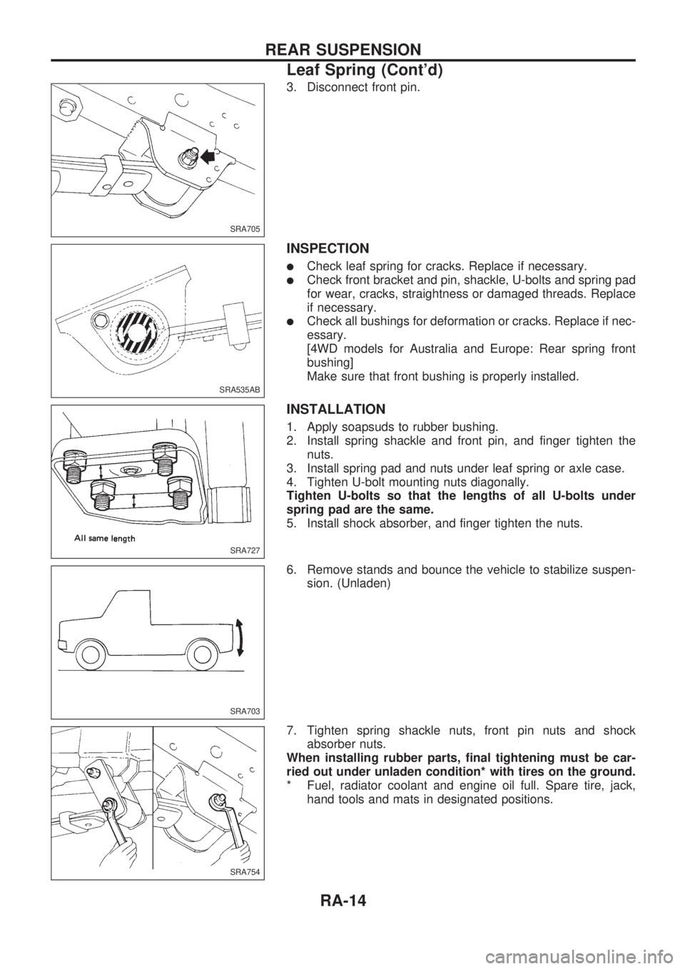
3. Disconnect front pin.
INSPECTION
lCheck leaf spring for cracks. Replace if necessary.
lCheck front bracket and pin, shackle, U-bolts and spring pad
for wear, cracks, straightness or damaged threads. Replace
if necessary.
lCheck all bushings for deformation or cracks. Replace if nec-
essary.
[4WD models for Australia and Europe: Rear spring front
bushing]
Make sure that front bushing is properly installed.
INSTALLATION
1. Apply soapsuds to rubber bushing.
2. Install spring shackle and front pin, and finger tighten the
nuts.
3. Install spring pad and nuts under leaf spring or axle case.
4. Tighten U-bolt mounting nuts diagonally.
Tighten U-bolts so that the lengths of all U-bolts under
spring pad are the same.
5. Install shock absorber, and finger tighten the nuts.
6. Remove stands and bounce the vehicle to stabilize suspen-
sion. (Unladen)
7. Tighten spring shackle nuts, front pin nuts and shock
absorber nuts.
When installing rubber parts, final tightening must be car-
ried out under unladen condition* with tires on the ground.
* Fuel, radiator coolant and engine oil full. Spare tire, jack,
hand tools and mats in designated positions.
SRA705
SRA535AB
.
SRA727
SRA703
SRA754
REAR SUSPENSION
Leaf Spring (Cont'd)
RA-14
Trending: ABS, brake, maintenance schedule, 4WD, engine oil, refrigerant type, weight
