NISSAN PICK-UP 1998 Repair Manual
PICK-UP 1998
NISSAN
NISSAN
https://www.carmanualsonline.info/img/5/57374/w960_57374-0.png
NISSAN PICK-UP 1998 Repair Manual
Trending: tires, height, headlamp, change wheel, cooling, jump start terminals, roof
Page 1241 of 1659
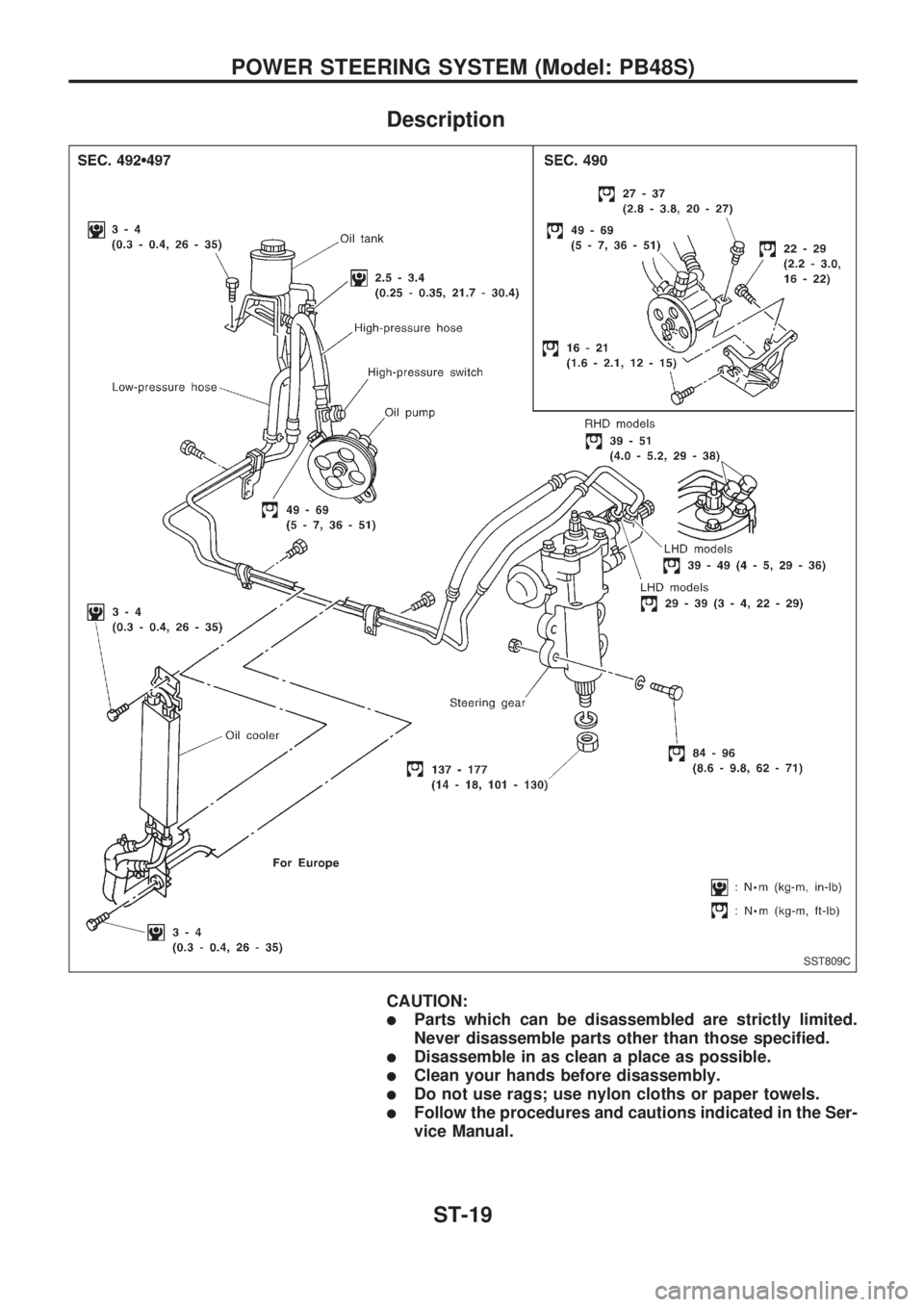
Description
CAUTION:
lParts which can be disassembled are strictly limited.
Never disassemble parts other than those specified.
lDisassemble in as clean a place as possible.
lClean your hands before disassembly.
lDo not use rags; use nylon cloths or paper towels.
lFollow the procedures and cautions indicated in the Ser-
vice Manual.
SST809C
POWER STEERING SYSTEM (Model: PB48S)
ST-19
Page 1242 of 1659
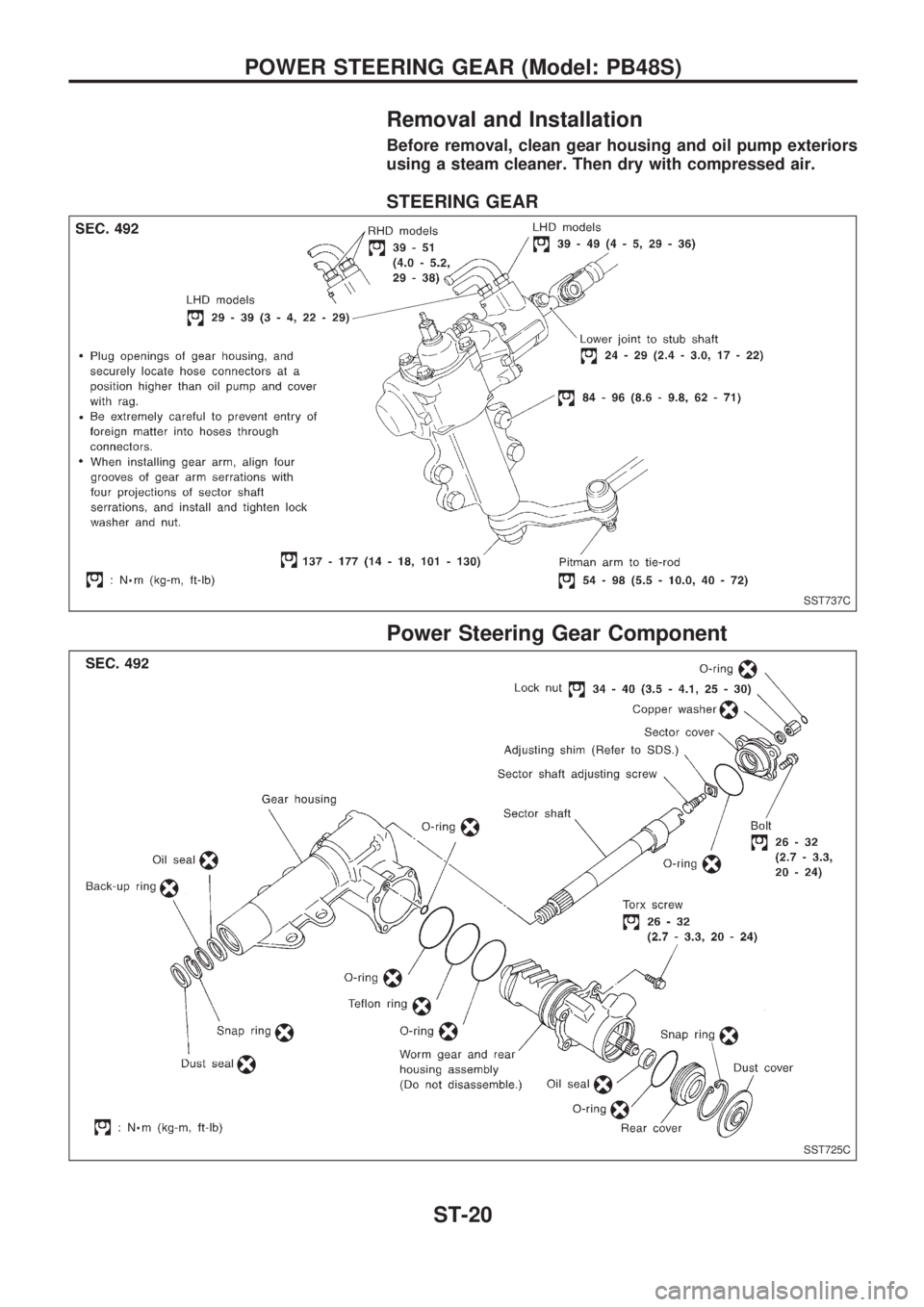
Removal and Installation
Before removal, clean gear housing and oil pump exteriors
using a steam cleaner. Then dry with compressed air.
STEERING GEAR
Power Steering Gear Component
SST737C
SST725C
POWER STEERING GEAR (Model: PB48S)
ST-20
Page 1243 of 1659
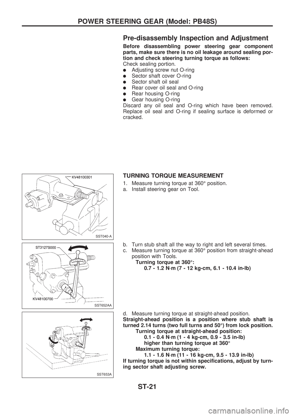
Pre-disassembly Inspection and Adjustment
Before disassembling power steering gear component
parts, make sure there is no oil leakage around sealing por-
tion and check steering turning torque as follows:
Check sealing portion.
lAdjusting screw nut O-ring
lSector shaft cover O-ring
lSector shaft oil seal
lRear cover oil seal and O-ring
lRear housing O-ring
lGear housing O-ring
Discard any oil seal and O-ring which have been removed.
Replace oil seal and O-ring if sealing surface is deformed or
cracked.
TURNING TORQUE MEASUREMENT
1. Measure turning torque at 360É position.
a. Install steering gear on Tool.
b. Turn stub shaft all the way to right and left several times.
c. Measure turning torque at 360É position from straight-ahead
position with Tools.
Turning torque at 360É:
0.7 - 1.2 N´m (7 - 12 kg-cm, 6.1 - 10.4 in-lb)
d. Measure turning torque at straight-ahead position.
Straight-ahead position is a position where stub shaft is
turned 2.14 turns (two full turns and 50É) from lock position.
Turning torque at straight-ahead position:
0.1 - 0.4 N´m (1 - 4 kg-cm, 0.9 - 3.5 in-lb)
higher than turning torque at 360É
Maximum turning torque:
1.1 - 1.6 N´m (11 - 16 kg-cm, 9.5 - 13.9 in-lb)
If turning torque is not within specifications, adjust by turn-
ing sector shaft adjusting screw.
SST040-A
SST652AA
SST653A
POWER STEERING GEAR (Model: PB48S)
ST-21
Page 1244 of 1659
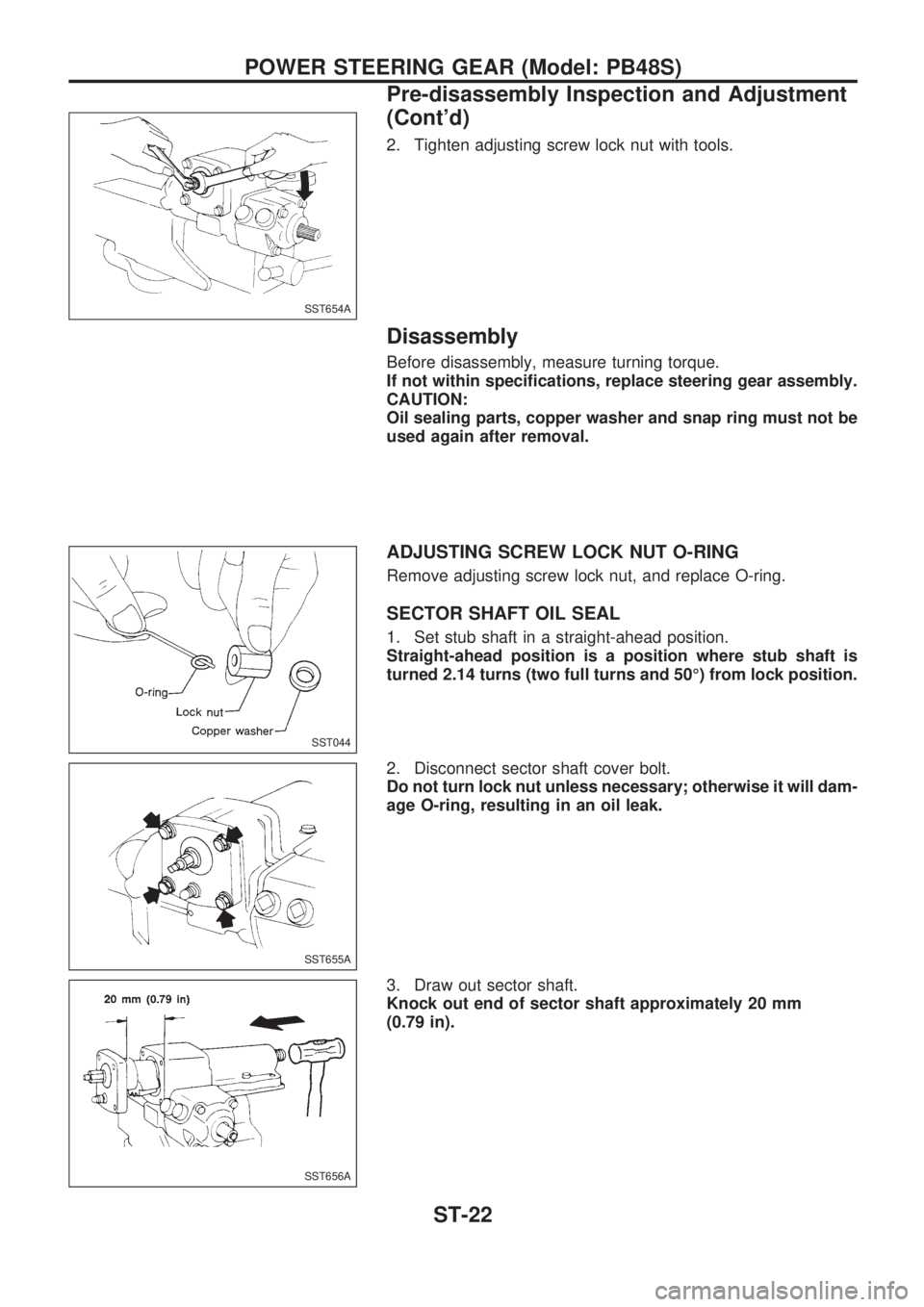
2. Tighten adjusting screw lock nut with tools.
Disassembly
Before disassembly, measure turning torque.
If not within specifications, replace steering gear assembly.
CAUTION:
Oil sealing parts, copper washer and snap ring must not be
used again after removal.
ADJUSTING SCREW LOCK NUT O-RING
Remove adjusting screw lock nut, and replace O-ring.
SECTOR SHAFT OIL SEAL
1. Set stub shaft in a straight-ahead position.
Straight-ahead position is a position where stub shaft is
turned 2.14 turns (two full turns and 50É) from lock position.
2. Disconnect sector shaft cover bolt.
Do not turn lock nut unless necessary; otherwise it will dam-
age O-ring, resulting in an oil leak.
3. Draw out sector shaft.
Knock out end of sector shaft approximately 20 mm
(0.79 in).
SST654A
SST044
SST655A
SST656A
POWER STEERING GEAR (Model: PB48S)
Pre-disassembly Inspection and Adjustment
(Cont'd)
ST-22
Page 1245 of 1659
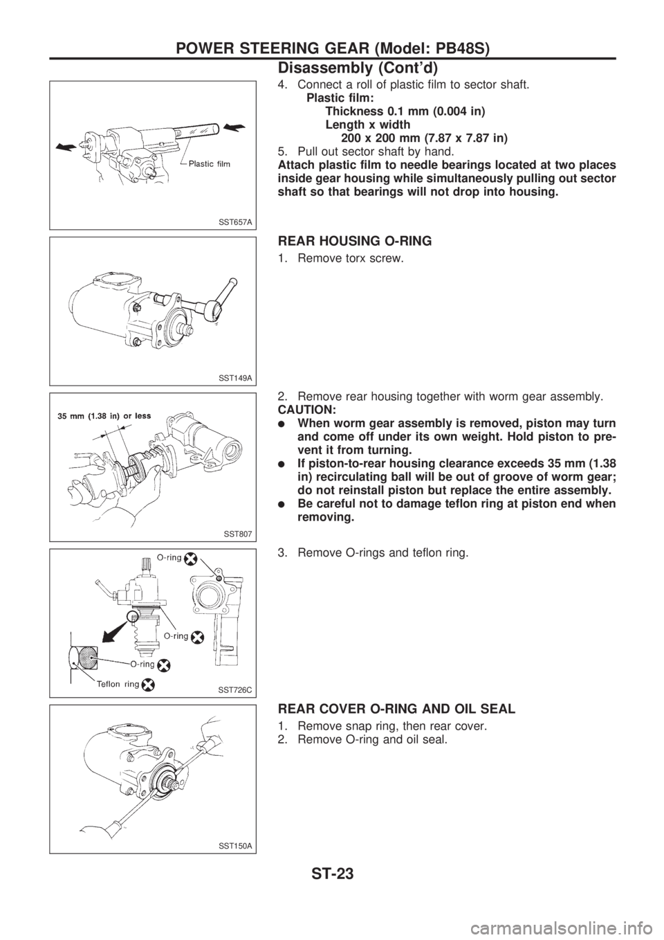
4. Connect a roll of plastic film to sector shaft.
Plastic film:
Thickness 0.1 mm (0.004 in)
Length x width
200 x 200 mm (7.87 x 7.87 in)
5. Pull out sector shaft by hand.
Attach plastic film to needle bearings located at two places
inside gear housing while simultaneously pulling out sector
shaft so that bearings will not drop into housing.
REAR HOUSING O-RING
1. Remove torx screw.
2. Remove rear housing together with worm gear assembly.
CAUTION:
lWhen worm gear assembly is removed, piston may turn
and come off under its own weight. Hold piston to pre-
vent it from turning.
lIf piston-to-rear housing clearance exceeds 35 mm (1.38
in) recirculating ball will be out of groove of worm gear;
do not reinstall piston but replace the entire assembly.
lBe careful not to damage teflon ring at piston end when
removing.
3. Remove O-rings and teflon ring.
REAR COVER O-RING AND OIL SEAL
1. Remove snap ring, then rear cover.
2. Remove O-ring and oil seal.
SST657A
SST149A
SST807
SST726C
SST150A
POWER STEERING GEAR (Model: PB48S)
Disassembly (Cont'd)
ST-23
Page 1246 of 1659
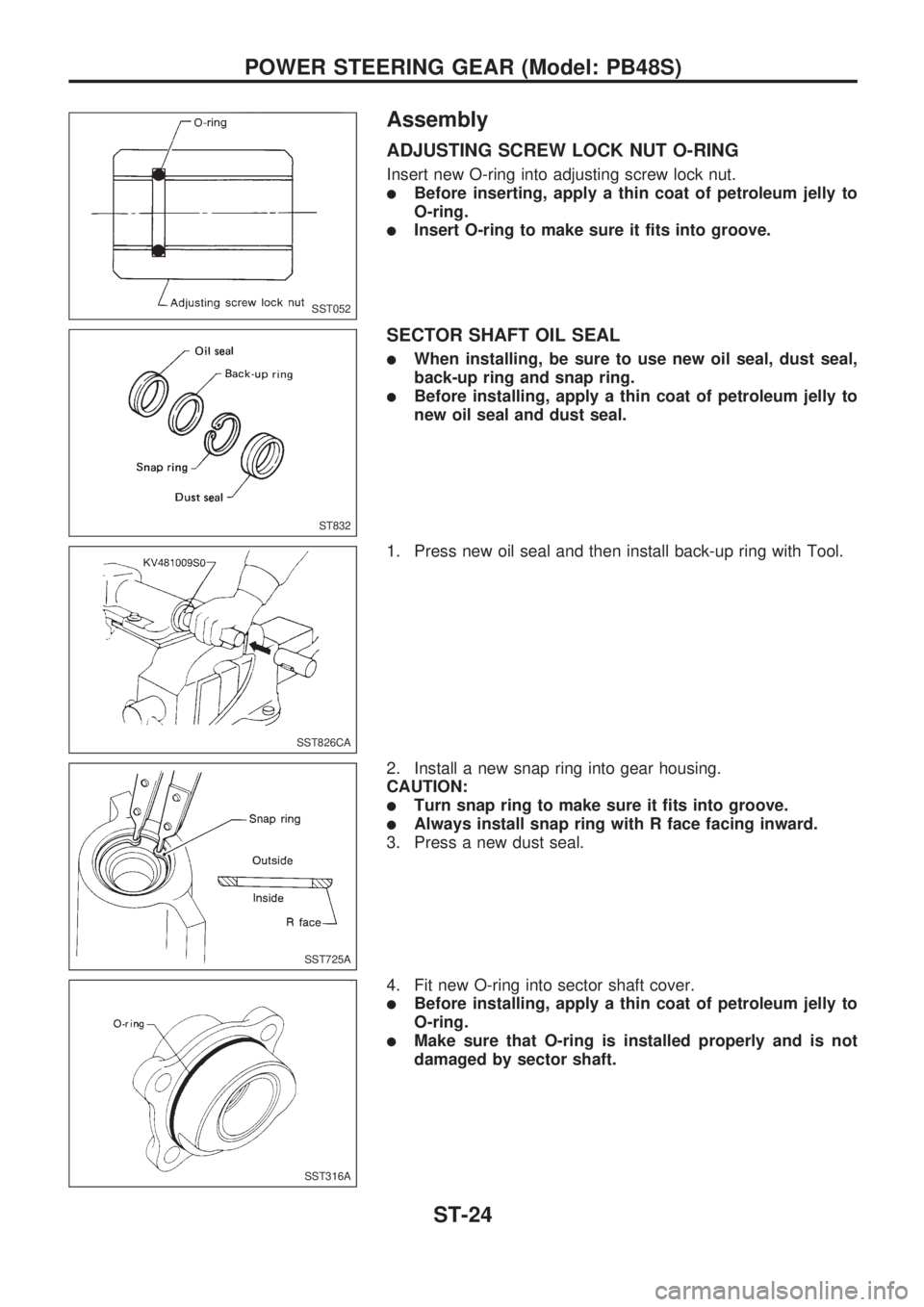
Assembly
ADJUSTING SCREW LOCK NUT O-RING
Insert new O-ring into adjusting screw lock nut.
lBefore inserting, apply a thin coat of petroleum jelly to
O-ring.
lInsert O-ring to make sure it fits into groove.
SECTOR SHAFT OIL SEAL
lWhen installing, be sure to use new oil seal, dust seal,
back-up ring and snap ring.
lBefore installing, apply a thin coat of petroleum jelly to
new oil seal and dust seal.
1. Press new oil seal and then install back-up ring with Tool.
2. Install a new snap ring into gear housing.
CAUTION:
lTurn snap ring to make sure it fits into groove.
lAlways install snap ring with R face facing inward.
3. Press a new dust seal.
4. Fit new O-ring into sector shaft cover.
lBefore installing, apply a thin coat of petroleum jelly to
O-ring.
lMake sure that O-ring is installed properly and is not
damaged by sector shaft.
SST052
ST832
SST826CA
SST725A
SST316A
POWER STEERING GEAR (Model: PB48S)
ST-24
Page 1247 of 1659
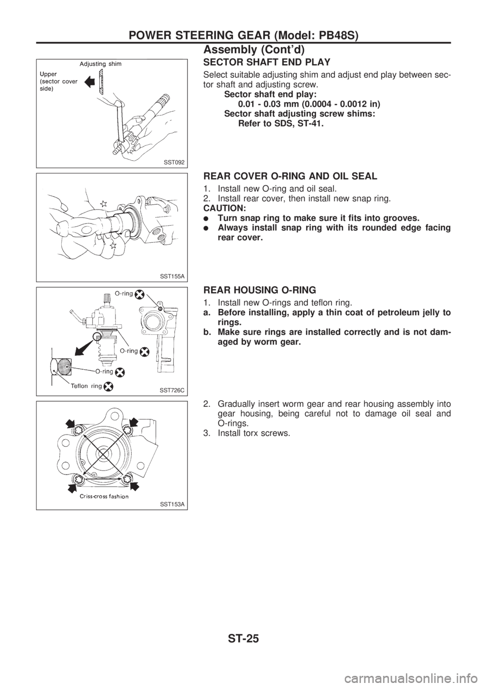
SECTOR SHAFT END PLAY
Select suitable adjusting shim and adjust end play between sec-
tor shaft and adjusting screw.
Sector shaft end play:
0.01 - 0.03 mm (0.0004 - 0.0012 in)
Sector shaft adjusting screw shims:
Refer to SDS, ST-41.
REAR COVER O-RING AND OIL SEAL
1. Install new O-ring and oil seal.
2. Install rear cover, then install new snap ring.
CAUTION:
lTurn snap ring to make sure it fits into grooves.
lAlways install snap ring with its rounded edge facing
rear cover.
REAR HOUSING O-RING
1. Install new O-rings and teflon ring.
a. Before installing, apply a thin coat of petroleum jelly to
rings.
b. Make sure rings are installed correctly and is not dam-
aged by worm gear.
2. Gradually insert worm gear and rear housing assembly into
gear housing, being careful not to damage oil seal and
O-rings.
3. Install torx screws.
SST092
SST155A
SST726C
SST153A
POWER STEERING GEAR (Model: PB48S)
Assembly (Cont'd)
ST-25
Page 1248 of 1659
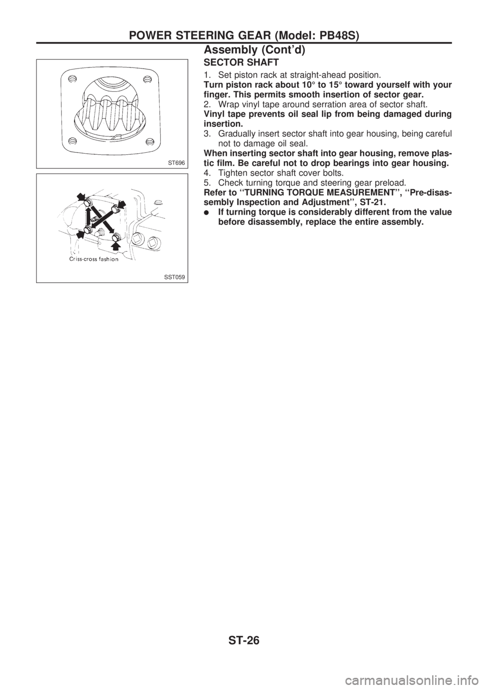
SECTOR SHAFT
1. Set piston rack at straight-ahead position.
Turn piston rack about 10É to 15É toward yourself with your
finger. This permits smooth insertion of sector gear.
2. Wrap vinyl tape around serration area of sector shaft.
Vinyl tape prevents oil seal lip from being damaged during
insertion.
3. Gradually insert sector shaft into gear housing, being careful
not to damage oil seal.
When inserting sector shaft into gear housing, remove plas-
tic film. Be careful not to drop bearings into gear housing.
4. Tighten sector shaft cover bolts.
5. Check turning torque and steering gear preload.
Refer to ``TURNING TORQUE MEASUREMENT'', ``Pre-disas-
sembly Inspection and Adjustment'', ST-21.
lIf turning torque is considerably different from the value
before disassembly, replace the entire assembly.
ST696
SST059
POWER STEERING GEAR (Model: PB48S)
Assembly (Cont'd)
ST-26
Page 1249 of 1659
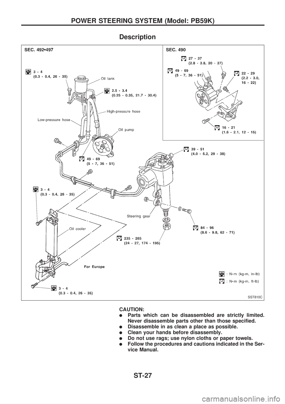
Description
CAUTION:
lParts which can be disassembled are strictly limited.
Never disassemble parts other than those specified.
lDisassemble in as clean a place as possible.
lClean your hands before disassembly.
lDo not use rags; use nylon cloths or paper towels.
lFollow the procedures and cautions indicated in the Ser-
vice Manual.
SST810C
POWER STEERING SYSTEM (Model: PB59K)
ST-27
Page 1250 of 1659
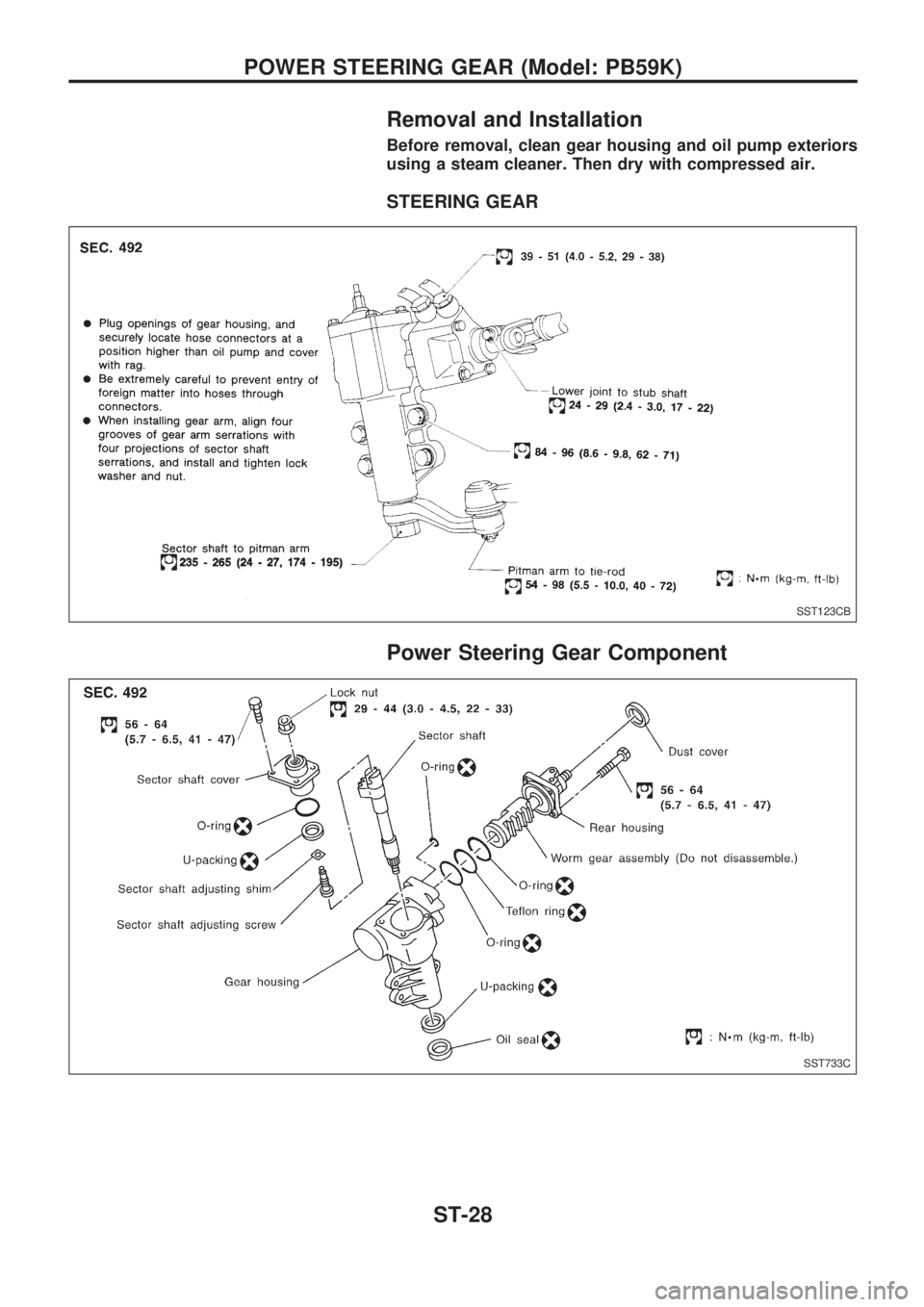
Removal and Installation
Before removal, clean gear housing and oil pump exteriors
using a steam cleaner. Then dry with compressed air.
STEERING GEAR
Power Steering Gear Component
SST123CB
SST733C
POWER STEERING GEAR (Model: PB59K)
ST-28
Trending: diagram, change wheel, maintenance, fuel filter, fuel cap release, jacking points, rear view mirror
