NISSAN PICK-UP 1998 Repair Manual
Manufacturer: NISSAN, Model Year: 1998, Model line: PICK-UP, Model: NISSAN PICK-UP 1998Pages: 1659, PDF Size: 53.39 MB
Page 1231 of 1659
![NISSAN PICK-UP 1998 Repair Manual Steering Wheel
REMOVAL AND INSTALLATION
1. Remove air bag module and spiral cable. Refer to RS sec-
tion [``Air Bag Module and Spiral Cable, ``SUPPLEMENTAL
RESTRAINT SYSTEM (SRS)]. (With air bag)
NISSAN PICK-UP 1998 Repair Manual Steering Wheel
REMOVAL AND INSTALLATION
1. Remove air bag module and spiral cable. Refer to RS sec-
tion [``Air Bag Module and Spiral Cable, ``SUPPLEMENTAL
RESTRAINT SYSTEM (SRS)]. (With air bag)](/img/5/57374/w960_57374-1230.png)
Steering Wheel
REMOVAL AND INSTALLATION
1. Remove air bag module and spiral cable. Refer to RS sec-
tion [``Air Bag Module and Spiral Cable'', ``SUPPLEMENTAL
RESTRAINT SYSTEM (SRS)'']. (With air bag)
Remove horn pad. (Without air bag)
2. Disconnect horn connector and remove steering wheel nut.
SST721C
SBF812EC
SST730C
STEERING WHEEL AND STEERING COLUMN
ST-9
Page 1232 of 1659
![NISSAN PICK-UP 1998 Repair Manual 3. Remove steering wheel using Tool.
lFor installation, refer to RS section [``Air Bag Module and
Spiral Cable, ``SUPPLEMENTAL RESTRAINT SYSTEM
(SRS)].
Steering Column
REMOVAL
CAUTION:
lThe rotati NISSAN PICK-UP 1998 Repair Manual 3. Remove steering wheel using Tool.
lFor installation, refer to RS section [``Air Bag Module and
Spiral Cable, ``SUPPLEMENTAL RESTRAINT SYSTEM
(SRS)].
Steering Column
REMOVAL
CAUTION:
lThe rotati](/img/5/57374/w960_57374-1231.png)
3. Remove steering wheel using Tool.
lFor installation, refer to RS section [``Air Bag Module and
Spiral Cable'', ``SUPPLEMENTAL RESTRAINT SYSTEM
(SRS)''].
Steering Column
REMOVAL
CAUTION:
lThe rotation of the spiral cable (SRS ``Air bag'' compo-
nent part) is limited. If the steering gear must be
removed, set the front wheels in the straight-ahead
direction.
Do not rotate the steering column while the steering gear
is removed.
lRemove the steering wheel before removing the steering
lower joint to avoid damaging the SRS spiral cable. Refer
to ST-9.
1. Remove steering wheel, refer to ST-9.
2. Remove steering column cover.
3. Remove instrument lower panel.
4. Disconnect combination switch electrical connectors and air
bag harness connector.
5. Remove dash insulator.
6. Remove bolt from lower joint.
7. Remove two steering column bolts and remove steering col-
umn.
INSTALLATION
lWhen installing steering column, finger-tighten all lower
bracket and clamp retaining bolts; then tighten them
securely. Make sure that undue stress is not applied to steer-
ing column.
lWhen fitting steering lower joint, be sure tightening bolt faces
cutout portion.
lAlign spiral cable correctly when installing steering wheel.
Refer to RS section [``Air Bag Module and Spiral Cable'',
``SUPPLEMENTAL RESTRAINT SYSTEM (SRS)''].
CAUTION:
After installation, turn steering wheel to make sure it moves
smoothly. Ensure the number of turns from the straight for-
ward position to left and right locks are the same. Be sure
that the steering wheel is in a neutral position when driving
straight ahead.
SST515B
SST666A
STEERING WHEEL AND STEERING COLUMN
Steering Wheel (Cont'd)
ST-10
Page 1233 of 1659
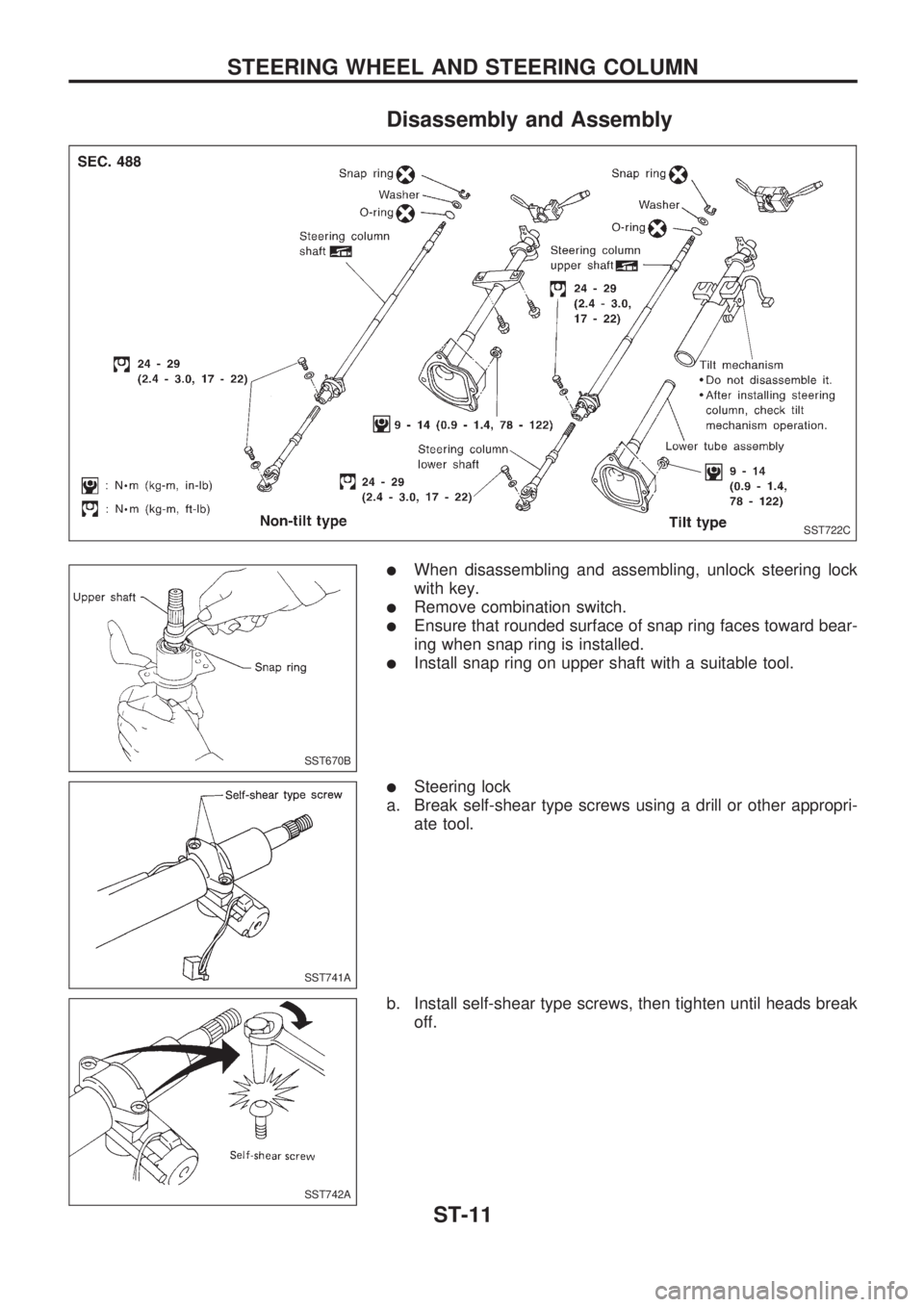
Disassembly and Assembly
lWhen disassembling and assembling, unlock steering lock
with key.
lRemove combination switch.
lEnsure that rounded surface of snap ring faces toward bear-
ing when snap ring is installed.
lInstall snap ring on upper shaft with a suitable tool.
lSteering lock
a. Break self-shear type screws using a drill or other appropri-
ate tool.
b. Install self-shear type screws, then tighten until heads break
off.
SST722C
SST670B
SST741A
SST742A
STEERING WHEEL AND STEERING COLUMN
ST-11
Page 1234 of 1659
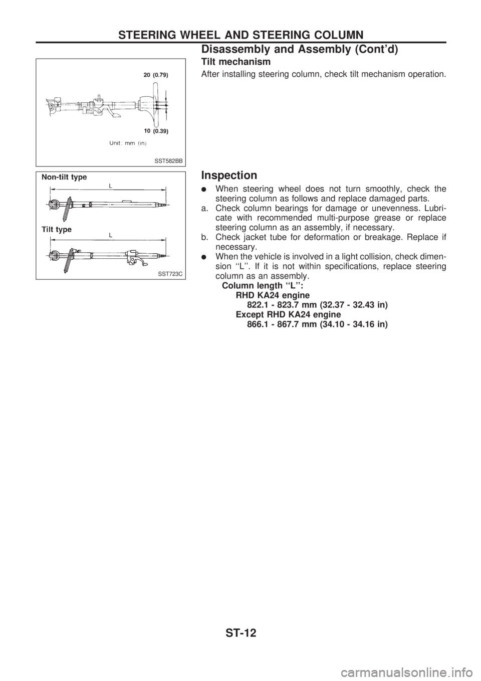
Tilt mechanism
After installing steering column, check tilt mechanism operation.
Inspection
lWhen steering wheel does not turn smoothly, check the
steering column as follows and replace damaged parts.
a. Check column bearings for damage or unevenness. Lubri-
cate with recommended multi-purpose grease or replace
steering column as an assembly, if necessary.
b. Check jacket tube for deformation or breakage. Replace if
necessary.
lWhen the vehicle is involved in a light collision, check dimen-
sion ``L''. If it is not within specifications, replace steering
column as an assembly.
Column length ``L'':
RHD KA24 engine
822.1 - 823.7 mm (32.37 - 32.43 in)
Except RHD KA24 engine
866.1 - 867.7 mm (34.10 - 34.16 in)
SST582BB
SST723C
STEERING WHEEL AND STEERING COLUMN
Disassembly and Assembly (Cont'd)
ST-12
Page 1235 of 1659
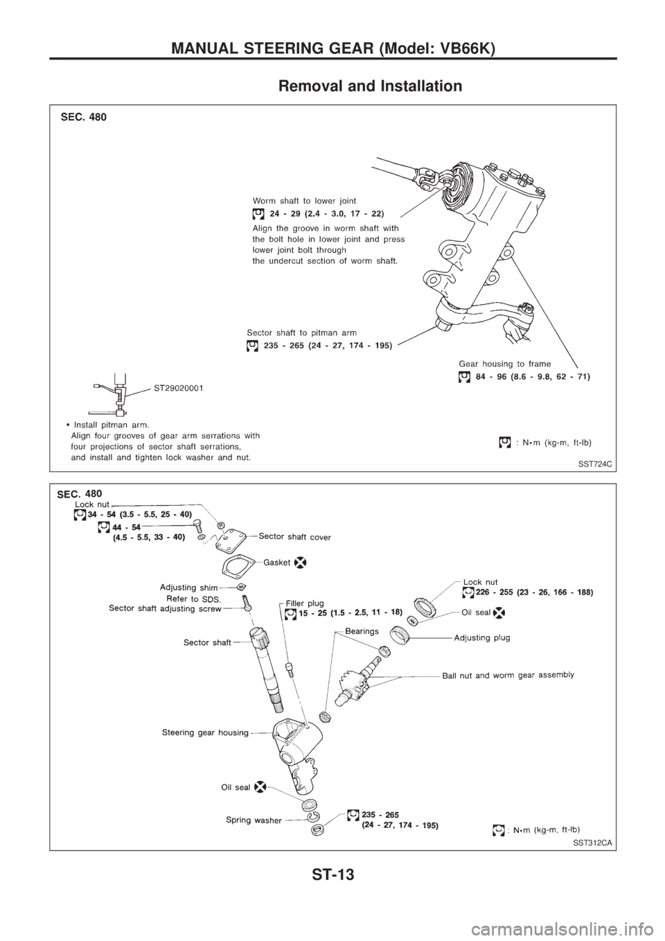
Removal and Installation
SST724C
SST312CA
MANUAL STEERING GEAR (Model: VB66K)
ST-13
Page 1236 of 1659
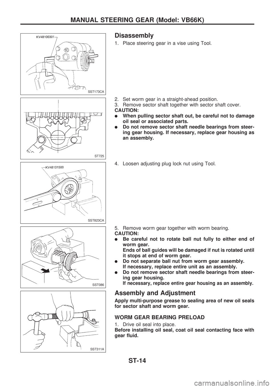
Disassembly
1. Place steering gear in a vise using Tool.
2. Set worm gear in a straight-ahead position.
3. Remove sector shaft together with sector shaft cover.
CAUTION:
lWhen pulling sector shaft out, be careful not to damage
oil seal or associated parts.
lDo not remove sector shaft needle bearings from steer-
ing gear housing. If necessary, replace gear housing as
an assembly.
4. Loosen adjusting plug lock nut using Tool.
5. Remove worm gear together with worm bearing.
CAUTION:
lBe careful not to rotate ball nut fully to either end of
worm gear.
Ends of ball guides will be damaged if nut is rotated until
it stops at end of worm gear.
lDo not separate ball nut from worm gear assembly.
If necessary, replace entire unit as an assembly.
lDo not remove sector shaft needle bearings from steer-
ing gear housing.
If necessary, replace entire gear housing as an assembly.
Assembly and Adjustment
Apply multi-purpose grease to sealing area of new oil seals
for sector shaft and worm gear.
WORM GEAR BEARING PRELOAD
1. Drive oil seal into place.
Before installing oil seal, coat oil seal contacting face with
gear fluid.
SST173CA
ST725
SST823CA
SST086
SST311A
MANUAL STEERING GEAR (Model: VB66K)
ST-14
Page 1237 of 1659
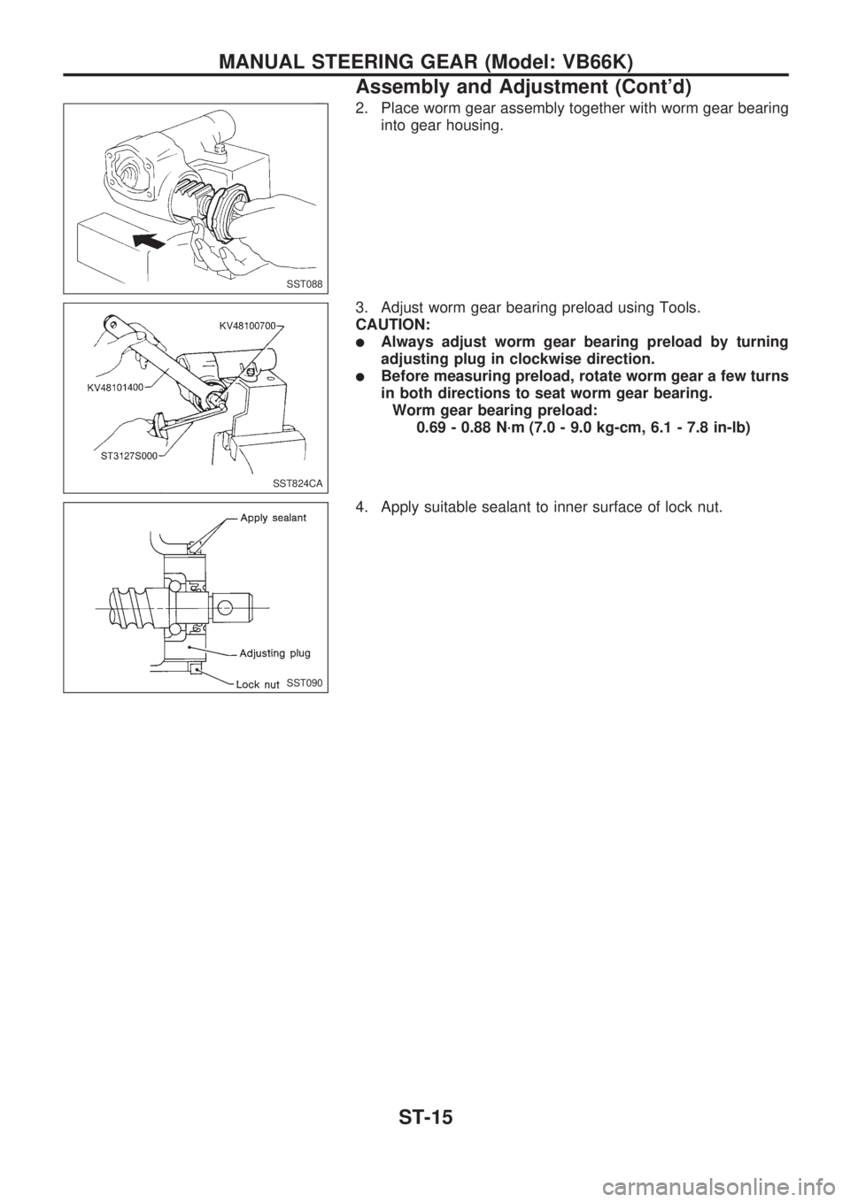
2. Place worm gear assembly together with worm gear bearing
into gear housing.
3. Adjust worm gear bearing preload using Tools.
CAUTION:
lAlways adjust worm gear bearing preload by turning
adjusting plug in clockwise direction.
lBefore measuring preload, rotate worm gear a few turns
in both directions to seat worm gear bearing.
Worm gear bearing preload:
0.69 - 0.88 N´m (7.0 - 9.0 kg-cm, 6.1 - 7.8 in-lb)
4. Apply suitable sealant to inner surface of lock nut.
SST088
SST824CA
SST090
MANUAL STEERING GEAR (Model: VB66K)
Assembly and Adjustment (Cont'd)
ST-15
Page 1238 of 1659
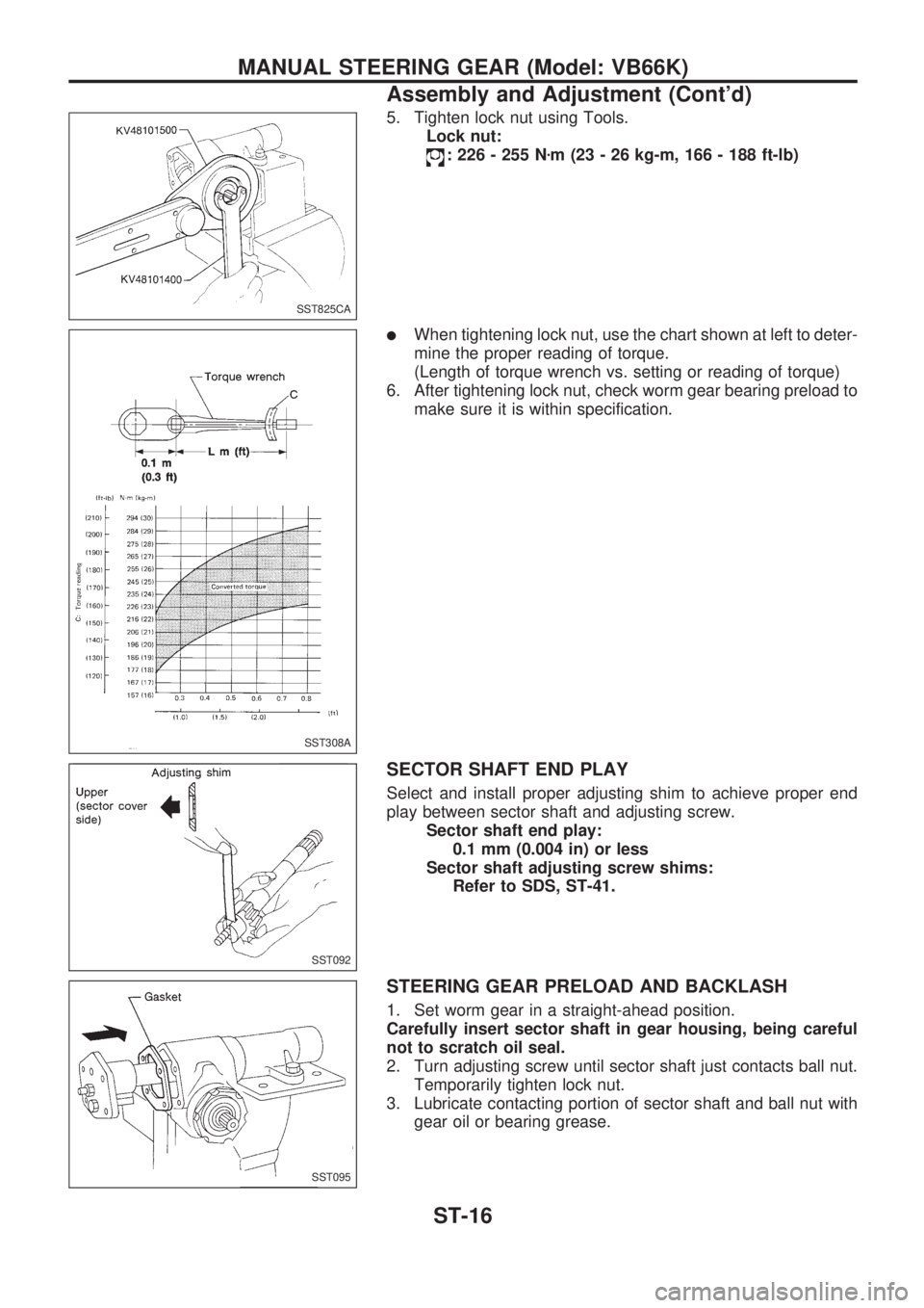
5. Tighten lock nut using Tools.
Lock nut:
: 226 - 255 Nzm (23 - 26 kg-m, 166 - 188 ft-lb)
lWhen tightening lock nut, use the chart shown at left to deter-
mine the proper reading of torque.
(Length of torque wrench vs. setting or reading of torque)
6. After tightening lock nut, check worm gear bearing preload to
make sure it is within specification.
SECTOR SHAFT END PLAY
Select and install proper adjusting shim to achieve proper end
play between sector shaft and adjusting screw.
Sector shaft end play:
0.1 mm (0.004 in) or less
Sector shaft adjusting screw shims:
Refer to SDS, ST-41.
STEERING GEAR PRELOAD AND BACKLASH
1. Set worm gear in a straight-ahead position.
Carefully insert sector shaft in gear housing, being careful
not to scratch oil seal.
2. Turn adjusting screw until sector shaft just contacts ball nut.
Temporarily tighten lock nut.
3. Lubricate contacting portion of sector shaft and ball nut with
gear oil or bearing grease.
SST825CA
SST308A
SST092
SST095
MANUAL STEERING GEAR (Model: VB66K)
Assembly and Adjustment (Cont'd)
ST-16
Page 1239 of 1659
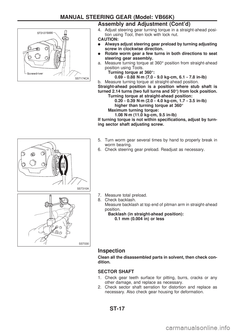
4. Adjust steering gear turning torque in a straight-ahead posi-
tion using Tool, then lock with lock nut.
CAUTION:
lAlways adjust steering gear preload by turning adjusting
screw in clockwise direction.
lRotate worm gear a few turns in both directions to seat
steering gear assembly.
a. Measure turning torque at 360É position from straight-ahead
position using Tools.
Turning torque at 360É:
0.69 - 0.88 N´m (7.0 - 9.0 kg-cm, 6.1 - 7.8 in-lb)
b. Measure turning torque at straight-ahead position.
Straight-ahead position is a position where stub shaft is
turned 2.14 turns (two full turns and 50É) from lock position.
Turning torque at straight-ahead position:
0.20 - 0.39 N´m (2.0 - 4.0 kg-cm, 1.7 - 3.5 in-lb)
higher than turning torque at 360É
Maximum turning torque:
1.08 N´m (11.0 kg-cm, 9.5 in-lb)
If turning torque is not within specifications, adjust by turn-
ing sector shaft adjusting screw.
5. Turn worm gear several times by hand to properly break in
worm bearing.
6. Check steering gear preload. Readjust as necessary.
7. Measure total preload.
8. Check backlash.
Measure backlash at top end of pitman arm in straight-ahead
position.
Backlash (in straight-ahead position):
0.1 mm (0.004 in) or less
Inspection
Clean all the disassembled parts in solvent, then check con-
dition.
SECTOR SHAFT
1. Check gear teeth surface for pitting, burrs, cracks or any
other damage, and replace as necessary.
2. Check sector shaft serration for distortion and replace as
necessary. Also check gear housing for deformation.
SST174CA
SST310A
SST030
MANUAL STEERING GEAR (Model: VB66K)
Assembly and Adjustment (Cont'd)
ST-17
Page 1240 of 1659
STEERING WORM ASSEMBLY
1. Inspect ball nut gear teeth surface. Replace if pitting, burrs,
wear or any other damage is found.
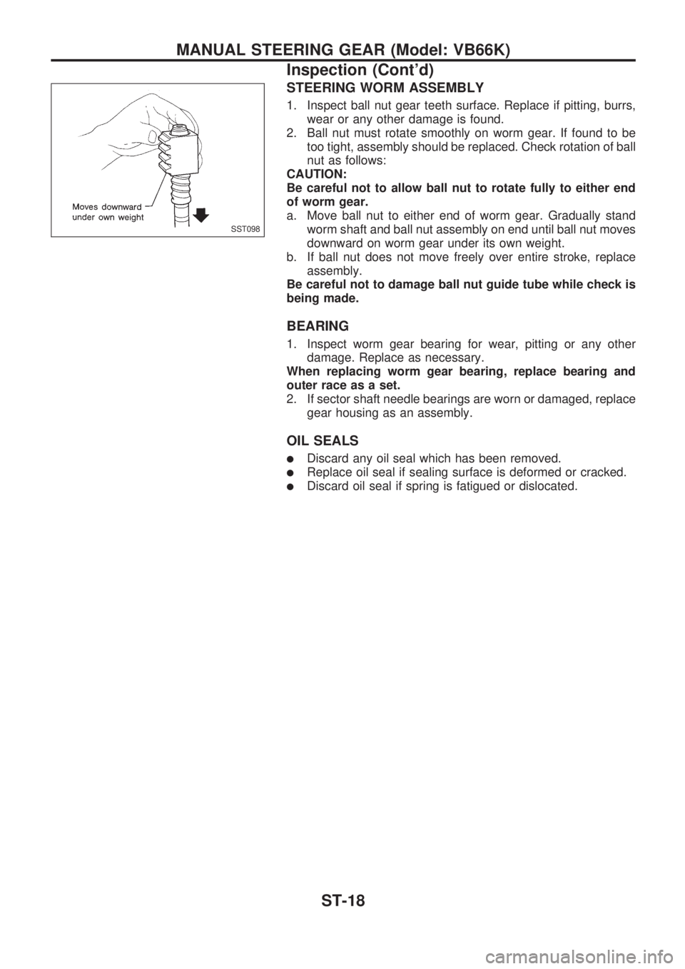
2. Ball nut must rotate smoothly on worm gear. If found to be
too tight, assembly should be replaced. Check rotation of ball
nut as follows:
CAUTION:
Be careful not to allow ball nut to rotate fully to either end
of worm gear.
a. Move ball nut to either end of worm gear. Gradually stand
worm shaft and ball nut assembly on end until ball nut moves
downward on worm gear under its own weight.
b. If ball nut does not move freely over entire stroke, replace
assembly.
Be careful not to damage ball nut guide tube while check is
being made.
BEARING
1. Inspect worm gear bearing for wear, pitting or any other
damage. Replace as necessary.
When replacing worm gear bearing, replace bearing and
outer race as a set.
2. If sector shaft needle bearings are worn or damaged, replace
gear housing as an assembly.
OIL SEALS
lDiscard any oil seal which has been removed.
lReplace oil seal if sealing surface is deformed or cracked.
lDiscard oil seal if spring is fatigued or dislocated.
SST098
MANUAL STEERING GEAR (Model: VB66K)
Inspection (Cont'd)
ST-18