NISSAN PICK-UP 1998 Repair Manual
PICK-UP 1998
NISSAN
NISSAN
https://www.carmanualsonline.info/img/5/57374/w960_57374-0.png
NISSAN PICK-UP 1998 Repair Manual
Trending: door lock, brake sensor, coolant, tow, coolant level, automatic transmission, coolant reservoir
Page 1281 of 1659
Mainshaft
DISASSEMBLY
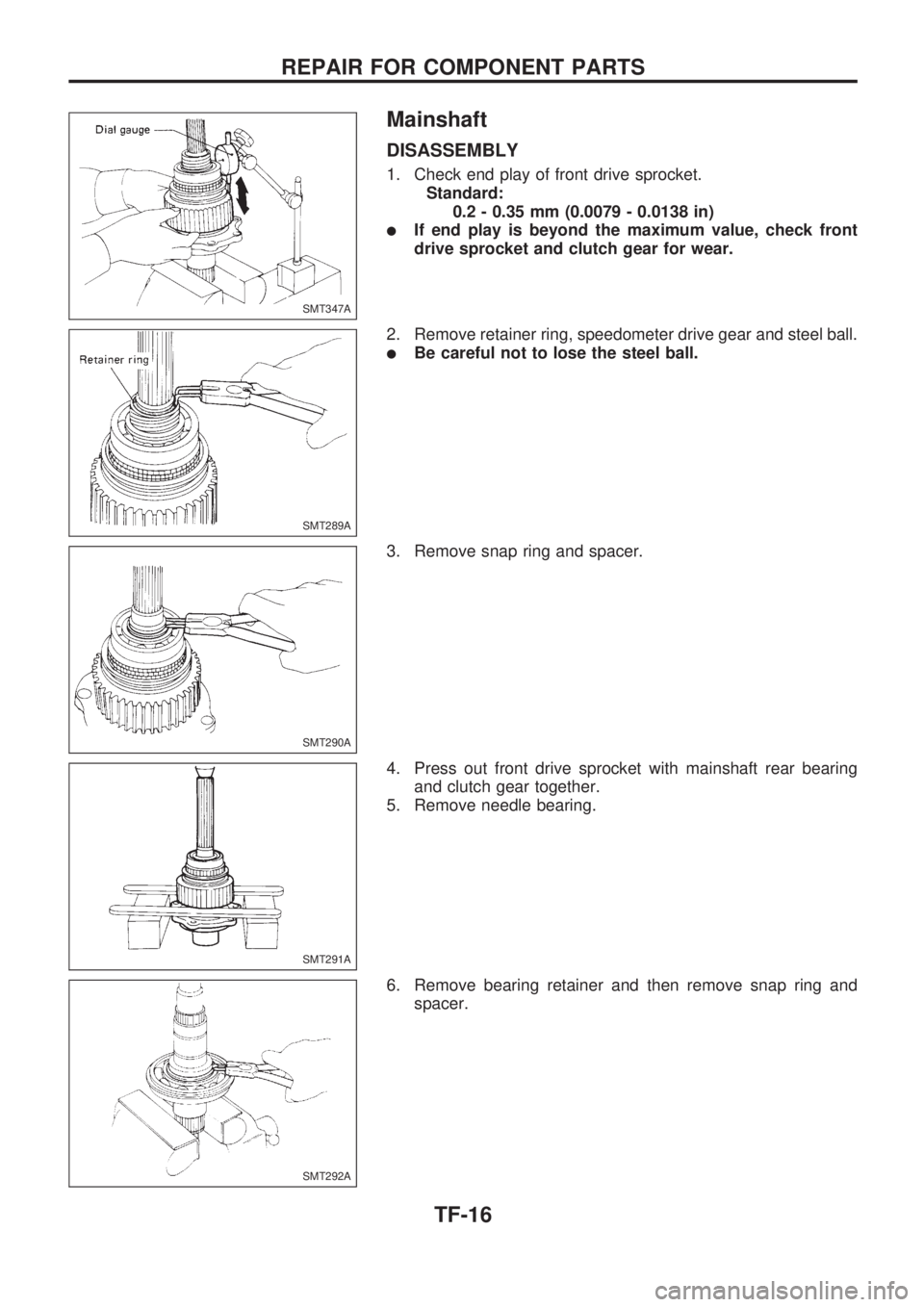
1. Check end play of front drive sprocket.
Standard:
0.2 - 0.35 mm (0.0079 - 0.0138 in)
lIf end play is beyond the maximum value, check front
drive sprocket and clutch gear for wear.
2. Remove retainer ring, speedometer drive gear and steel ball.
lBe careful not to lose the steel ball.
3. Remove snap ring and spacer.
4. Press out front drive sprocket with mainshaft rear bearing
and clutch gear together.
5. Remove needle bearing.
6. Remove bearing retainer and then remove snap ring and
spacer.
SMT347A
SMT289A
SMT290A
SMT291A
SMT292A
REPAIR FOR COMPONENT PARTS
TF-16
Page 1282 of 1659
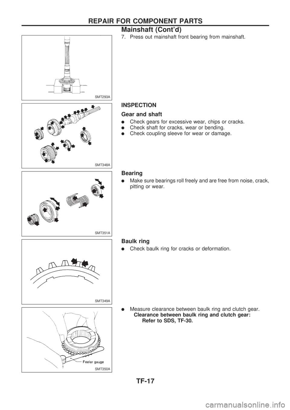
7. Press out mainshaft front bearing from mainshaft.
INSPECTION
Gear and shaft
lCheck gears for excessive wear, chips or cracks.
lCheck shaft for cracks, wear or bending.
lCheck coupling sleeve for wear or damage.
Bearing
lMake sure bearings roll freely and are free from noise, crack,
pitting or wear.
Baulk ring
lCheck baulk ring for cracks or deformation.
lMeasure clearance between baulk ring and clutch gear.
Clearance between baulk ring and clutch gear:
Refer to SDS, TF-30.
SMT293A
SMT348A
SMT351A
SMT349A
SMT350A
REPAIR FOR COMPONENT PARTS
Mainshaft (Cont'd)
TF-17
Page 1283 of 1659
ASSEMBLY
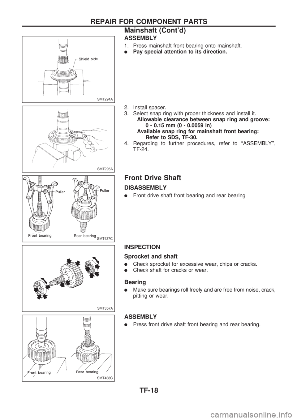
1. Press mainshaft front bearing onto mainshaft.
lPay special attention to its direction.
2. Install spacer.
3. Select snap ring with proper thickness and install it.
Allowable clearance between snap ring and groove:
0 - 0.15 mm (0 - 0.0059 in)
Available snap ring for mainshaft front bearing:
Refer to SDS, TF-30.
4. Regarding to further procedures, refer to ``ASSEMBLY'',
TF-24.
Front Drive Shaft
DISASSEMBLY
lFront drive shaft front bearing and rear bearing
INSPECTION
Sprocket and shaft
lCheck sprocket for excessive wear, chips or cracks.
lCheck shaft for cracks or wear.
Bearing
lMake sure bearings roll freely and are free from noise, crack,
pitting or wear.
ASSEMBLY
lPress front drive shaft front bearing and rear bearing.
SMT294A
SMT295A
SMT437C
SMT357A
SMT438C
REPAIR FOR COMPONENT PARTS
Mainshaft (Cont'd)
TF-18
Page 1284 of 1659
Counter Gear
DISASSEMBLY
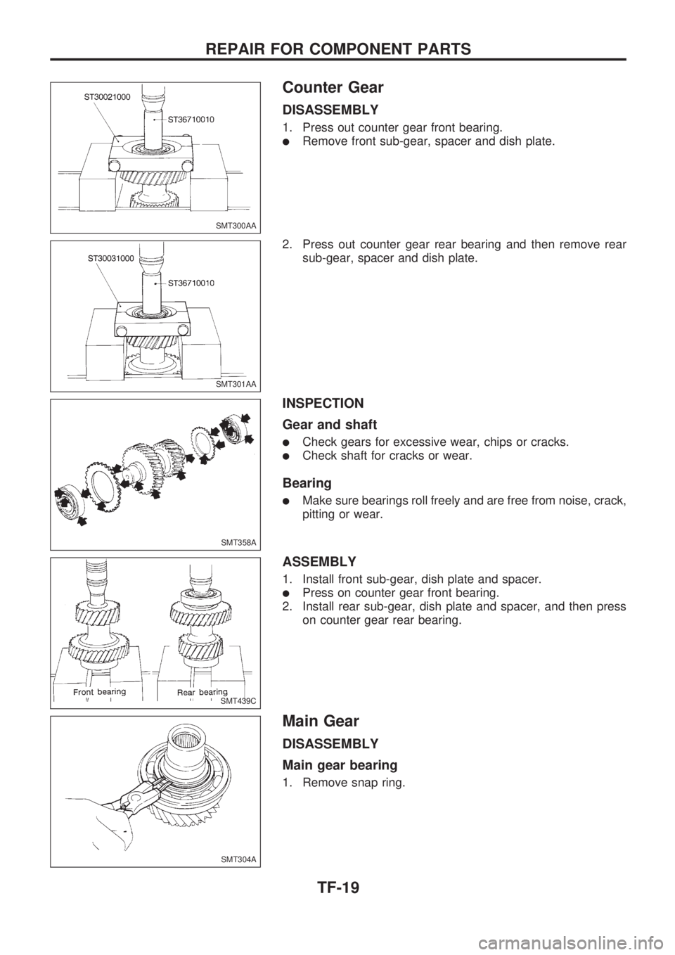
1. Press out counter gear front bearing.
lRemove front sub-gear, spacer and dish plate.
2. Press out counter gear rear bearing and then remove rear
sub-gear, spacer and dish plate.
INSPECTION
Gear and shaft
lCheck gears for excessive wear, chips or cracks.
lCheck shaft for cracks or wear.
Bearing
lMake sure bearings roll freely and are free from noise, crack,
pitting or wear.
ASSEMBLY
1. Install front sub-gear, dish plate and spacer.
lPress on counter gear front bearing.
2. Install rear sub-gear, dish plate and spacer, and then press
on counter gear rear bearing.
Main Gear
DISASSEMBLY
Main gear bearing
1. Remove snap ring.
SMT300AA
SMT301AA
SMT358A
SMT439C
SMT304A
REPAIR FOR COMPONENT PARTS
TF-19
Page 1285 of 1659
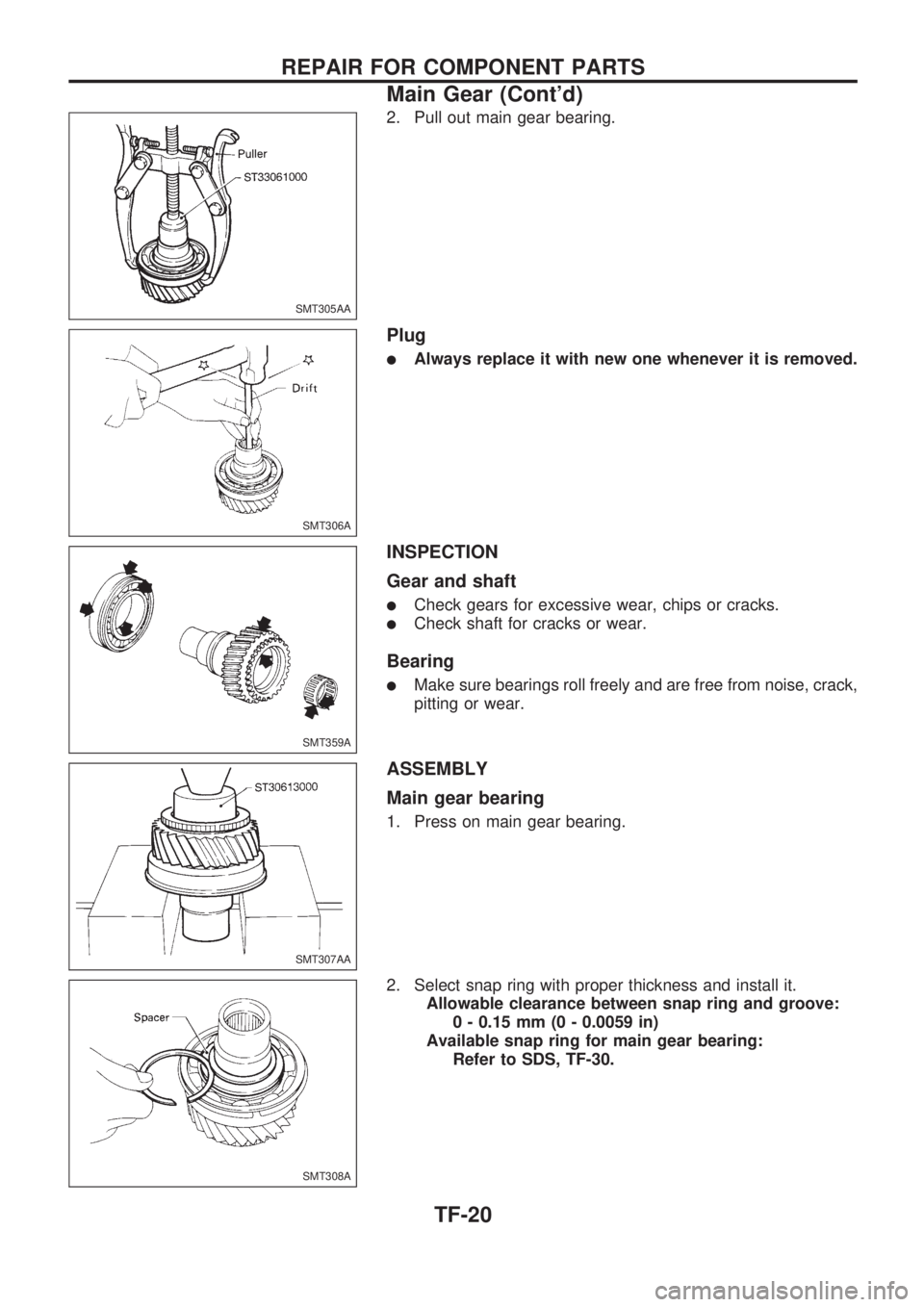
2. Pull out main gear bearing.
Plug
lAlways replace it with new one whenever it is removed.
INSPECTION
Gear and shaft
lCheck gears for excessive wear, chips or cracks.
lCheck shaft for cracks or wear.
Bearing
lMake sure bearings roll freely and are free from noise, crack,
pitting or wear.
ASSEMBLY
Main gear bearing
1. Press on main gear bearing.
2. Select snap ring with proper thickness and install it.
Allowable clearance between snap ring and groove:
0 - 0.15 mm (0 - 0.0059 in)
Available snap ring for main gear bearing:
Refer to SDS, TF-30.
SMT305AA
SMT306A
SMT359A
SMT307AA
SMT308A
REPAIR FOR COMPONENT PARTS
Main Gear (Cont'd)
TF-20
Page 1286 of 1659
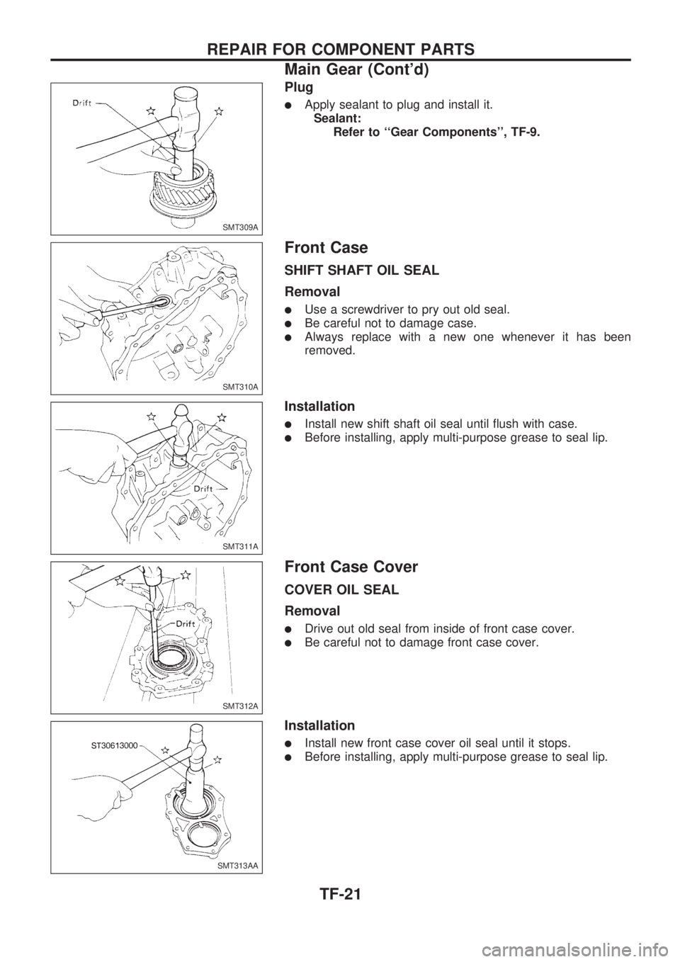
Plug
lApply sealant to plug and install it.
Sealant:
Refer to ``Gear Components'', TF-9.
Front Case
SHIFT SHAFT OIL SEAL
Removal
lUse a screwdriver to pry out old seal.
lBe careful not to damage case.
lAlways replace with a new one whenever it has been
removed.
Installation
lInstall new shift shaft oil seal until flush with case.
lBefore installing, apply multi-purpose grease to seal lip.
Front Case Cover
COVER OIL SEAL
Removal
lDrive out old seal from inside of front case cover.
lBe careful not to damage front case cover.
Installation
lInstall new front case cover oil seal until it stops.
lBefore installing, apply multi-purpose grease to seal lip.
SMT309A
SMT310A
SMT311A
SMT312A
SMT313AA
REPAIR FOR COMPONENT PARTS
Main Gear (Cont'd)
TF-21
Page 1287 of 1659
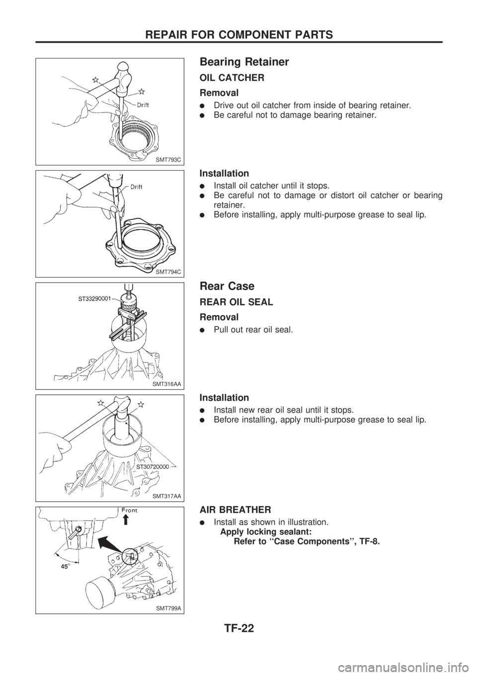
Bearing Retainer
OIL CATCHER
Removal
lDrive out oil catcher from inside of bearing retainer.
lBe careful not to damage bearing retainer.
Installation
lInstall oil catcher until it stops.
lBe careful not to damage or distort oil catcher or bearing
retainer.
lBefore installing, apply multi-purpose grease to seal lip.
Rear Case
REAR OIL SEAL
Removal
lPull out rear oil seal.
Installation
lInstall new rear oil seal until it stops.
lBefore installing, apply multi-purpose grease to seal lip.
AIR BREATHER
lInstall as shown in illustration.
Apply locking sealant:
Refer to ``Case Components'', TF-8.
SMT793C
SMT794C
SMT316AA
SMT317AA
SMT799A
REPAIR FOR COMPONENT PARTS
TF-22
Page 1288 of 1659
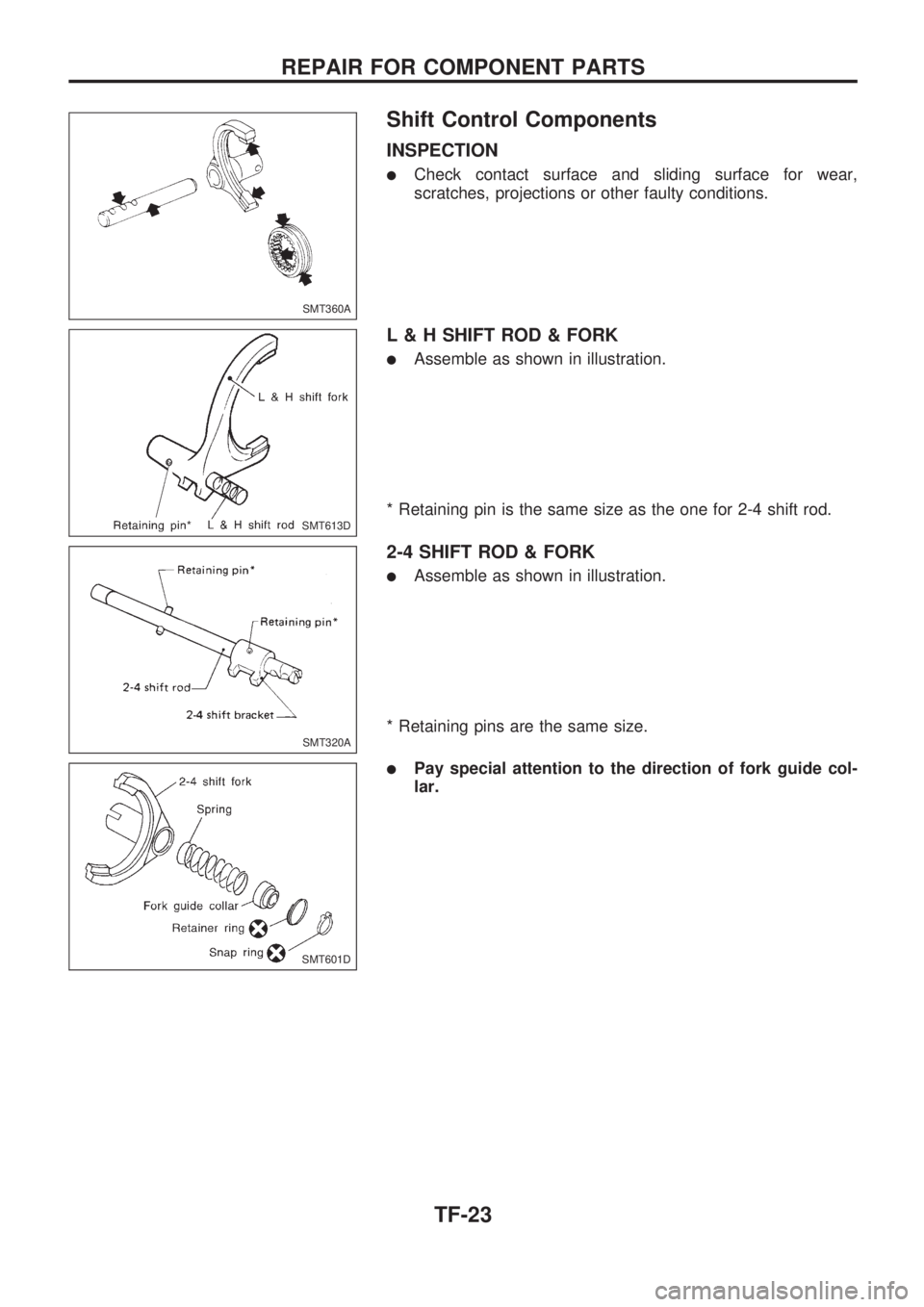
Shift Control Components
INSPECTION
lCheck contact surface and sliding surface for wear,
scratches, projections or other faulty conditions.
L & H SHIFT ROD & FORK
lAssemble as shown in illustration.
* Retaining pin is the same size as the one for 2-4 shift rod.
2-4 SHIFT ROD & FORK
lAssemble as shown in illustration.
* Retaining pins are the same size.
lPay special attention to the direction of fork guide col-
lar.
SMT360A
SMT613D
SMT320A
SMT601D
REPAIR FOR COMPONENT PARTS
TF-23
Page 1289 of 1659
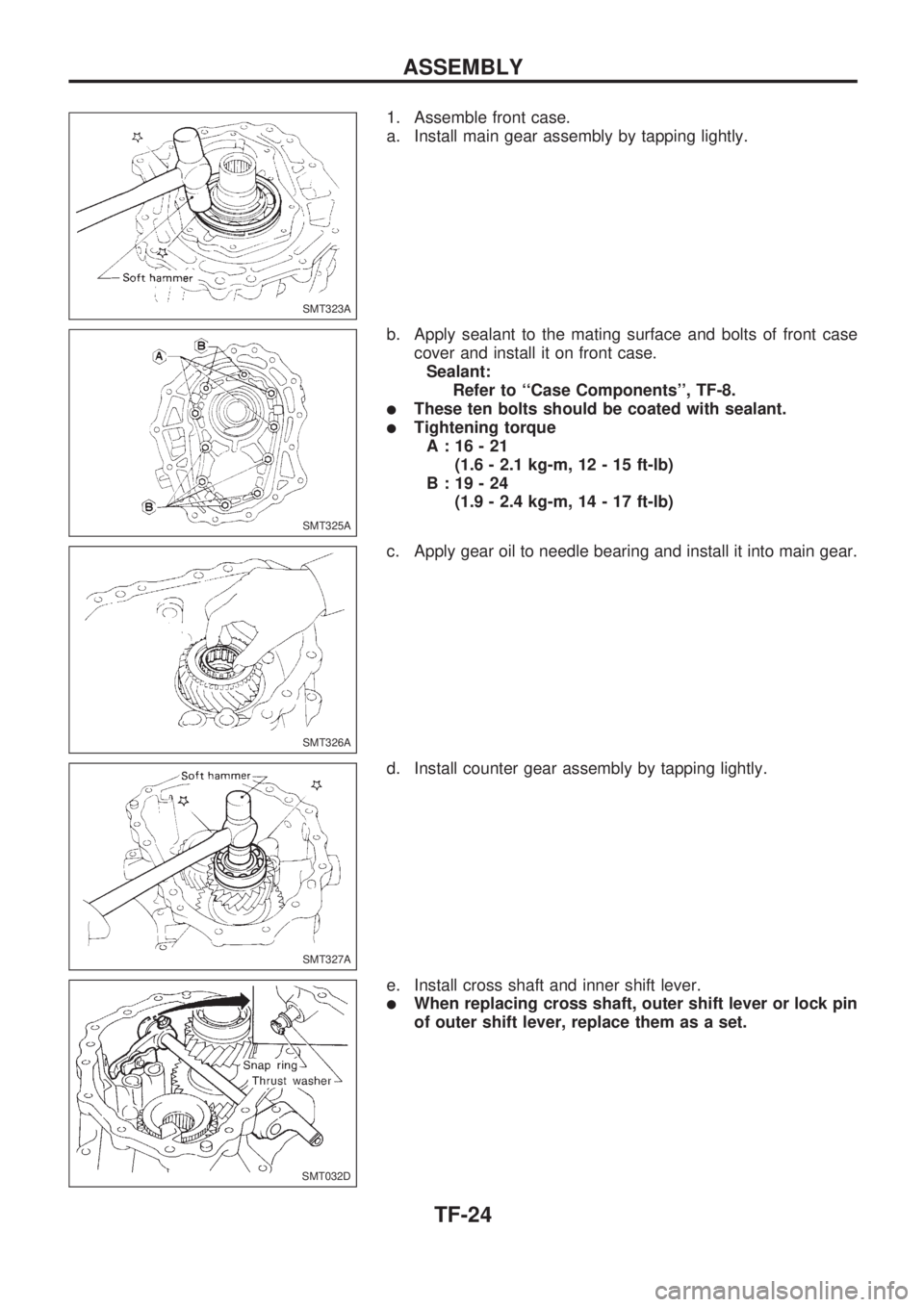
1. Assemble front case.
a. Install main gear assembly by tapping lightly.
b. Apply sealant to the mating surface and bolts of front case
cover and install it on front case.
Sealant:
Refer to ``Case Components'', TF-8.
lThese ten bolts should be coated with sealant.
lTightening torque
A:16-21
(1.6 - 2.1 kg-m, 12 - 15 ft-lb)
B:19-24
(1.9 - 2.4 kg-m, 14 - 17 ft-lb)
c. Apply gear oil to needle bearing and install it into main gear.
d. Install counter gear assembly by tapping lightly.
e. Install cross shaft and inner shift lever.
lWhen replacing cross shaft, outer shift lever or lock pin
of outer shift lever, replace them as a set.
SMT323A
SMT325A
SMT326A
SMT327A
SMT032D
ASSEMBLY
TF-24
Page 1290 of 1659
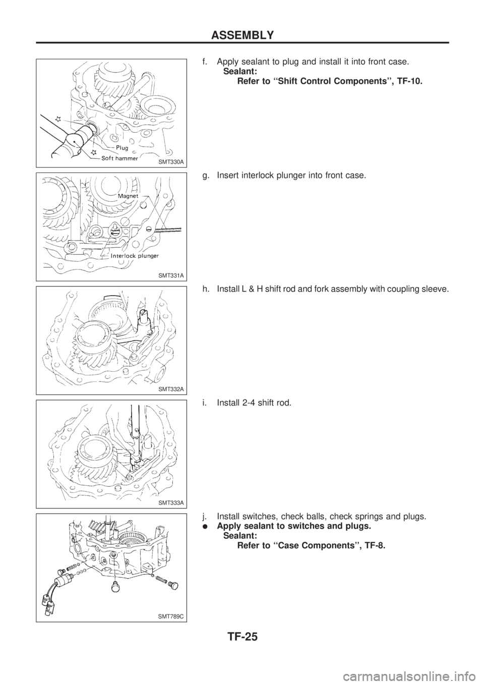
f. Apply sealant to plug and install it into front case.
Sealant:
Refer to ``Shift Control Components'', TF-10.
g. Insert interlock plunger into front case.
h. InstallL&Hshift rod and fork assembly with coupling sleeve.
i. Install 2-4 shift rod.
j. Install switches, check balls, check springs and plugs.
lApply sealant to switches and plugs.
Sealant:
Refer to ``Case Components'', TF-8.
SMT330A
SMT331A
SMT332A
SMT333A
SMT789C
ASSEMBLY
TF-25
Trending: rear view mirror, interior lights, inflation pressure, wiper fluid, tire type, high beam, 4WD
