NISSAN PICK-UP 1998 Repair Manual
Manufacturer: NISSAN, Model Year: 1998, Model line: PICK-UP, Model: NISSAN PICK-UP 1998Pages: 1659, PDF Size: 53.39 MB
Page 791 of 1659
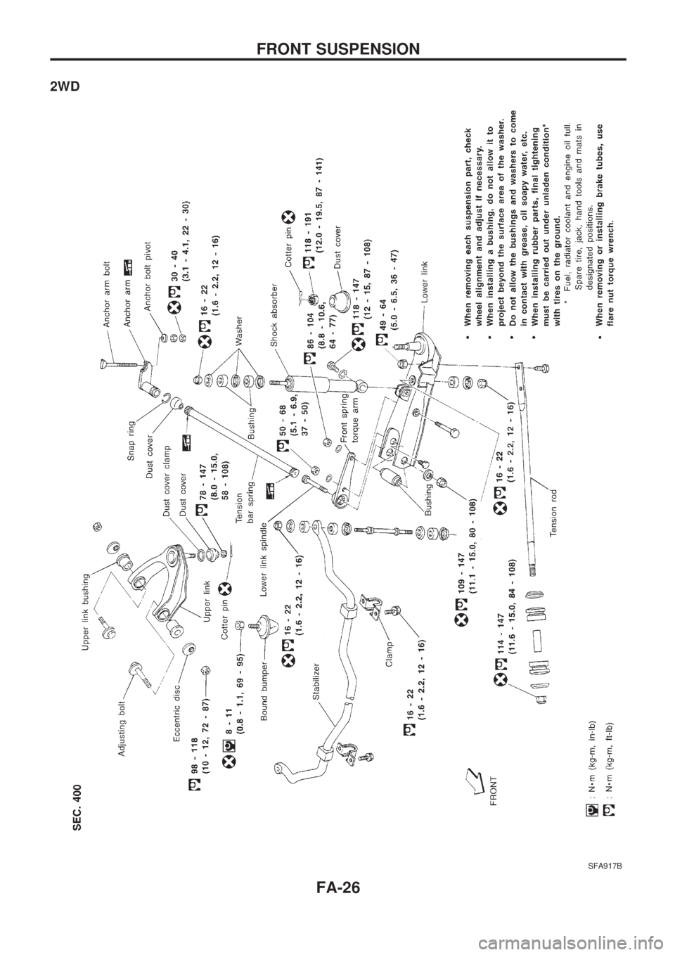
2WD
SFA917B
FRONT SUSPENSION
FA-26
Page 792 of 1659
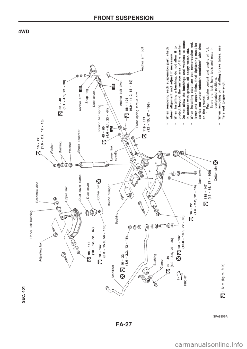
4WD
SFA835BA
FRONT SUSPENSION
FA-27
Page 793 of 1659
Shock Absorber
REMOVAL AND INSTALLATION
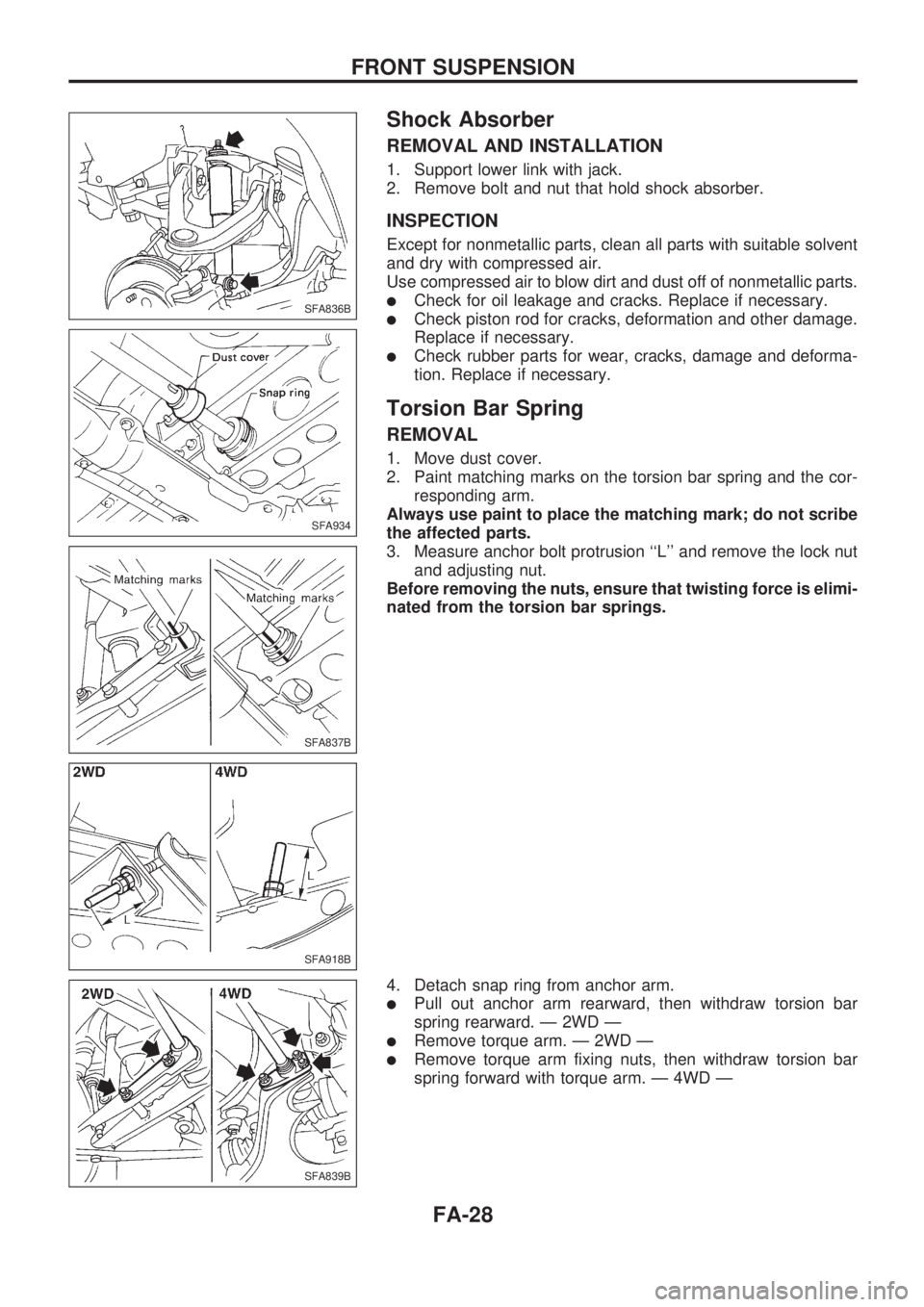
1. Support lower link with jack.
2. Remove bolt and nut that hold shock absorber.
INSPECTION
Except for nonmetallic parts, clean all parts with suitable solvent
and dry with compressed air.
Use compressed air to blow dirt and dust off of nonmetallic parts.
lCheck for oil leakage and cracks. Replace if necessary.
lCheck piston rod for cracks, deformation and other damage.
Replace if necessary.
lCheck rubber parts for wear, cracks, damage and deforma-
tion. Replace if necessary.
Torsion Bar Spring
REMOVAL
1. Move dust cover.
2. Paint matching marks on the torsion bar spring and the cor-
responding arm.
Always use paint to place the matching mark; do not scribe
the affected parts.
3. Measure anchor bolt protrusion ``L'' and remove the lock nut
and adjusting nut.
Before removing the nuts, ensure that twisting force is elimi-
nated from the torsion bar springs.
4. Detach snap ring from anchor arm.
lPull out anchor arm rearward, then withdraw torsion bar
spring rearward. Ð 2WD Ð
lRemove torque arm. Ð 2WD Ð
lRemove torque arm fixing nuts, then withdraw torsion bar
spring forward with torque arm. Ð 4WD Ð
SFA836B
SFA934
SFA837B
SFA918B
SFA839B
FRONT SUSPENSION
FA-28
Page 794 of 1659
INSPECTION
lCheck torsion bar spring for wear, twist, bend and other
damage.
lCheck serrations of each part for cracks, wear, twist and
other damage.
lCheck dust cover for cracks.
INSTALLATION AND ADJUSTMENT
Adjustment of anchor arm adjusting nut is in tightening
direction only.
Do not adjust by loosening anchor arm adjusting nut.
1. Install torque arm to lower link. Ð 2WD Ð
2. Coat multi-purpose grease on the serration of torsion bar
spring.
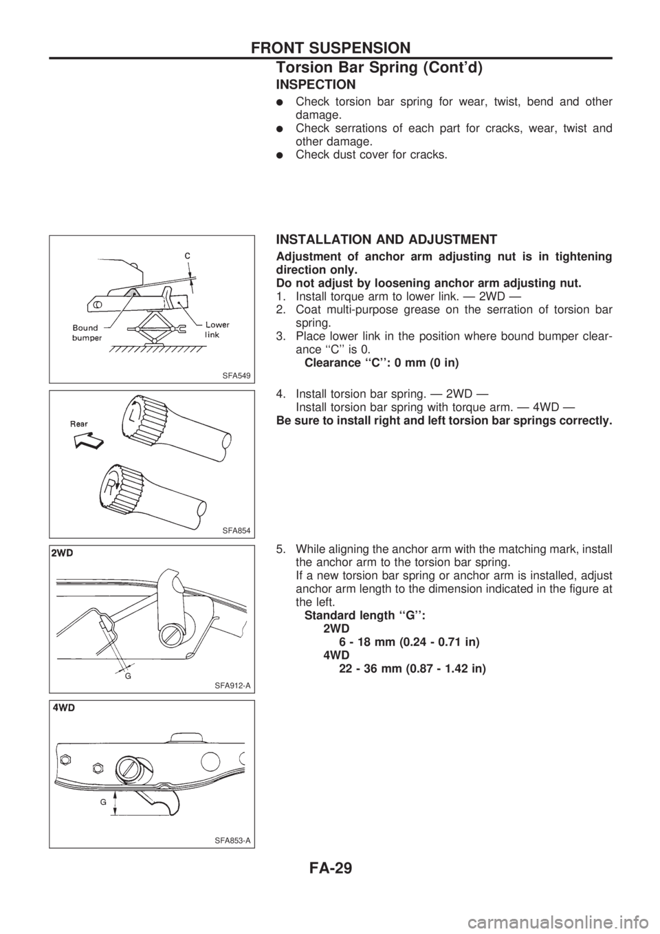
3. Place lower link in the position where bound bumper clear-
ance ``C'' is 0.
Clearance ``C'': 0 mm (0 in)
4. Install torsion bar spring. Ð 2WD Ð
Install torsion bar spring with torque arm. Ð 4WD Ð
Be sure to install right and left torsion bar springs correctly.
5. While aligning the anchor arm with the matching mark, install
the anchor arm to the torsion bar spring.
If a new torsion bar spring or anchor arm is installed, adjust
anchor arm length to the dimension indicated in the figure at
the left.
Standard length ``G'':
2WD
6 - 18 mm (0.24 - 0.71 in)
4WD
22 - 36 mm (0.87 - 1.42 in)
SFA549
SFA854
SFA912-A
SFA853-A
FRONT SUSPENSION
Torsion Bar Spring (Cont'd)
FA-29
Page 795 of 1659
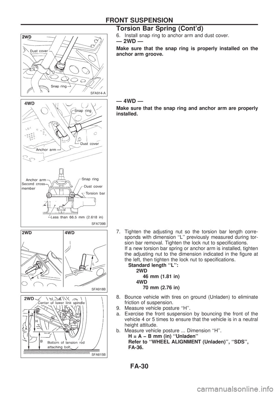
6. Install snap ring to anchor arm and dust cover.
Ð 2WD Ð
Make sure that the snap ring is properly installed on the
anchor arm groove.
Ð 4WD Ð
Make sure that the snap ring and anchor arm are properly
installed.
7. Tighten the adjusting nut so the torsion bar length corre-
sponds with dimension ``L'' previously measured during tor-
sion bar removal. Tighten the lock nut to specifications.
If a new torsion bar spring or anchor arm is installed, tighten
the adjusting nut to the dimension indicated in the figure at
the left, then tighten the lock nut to specifications.
Standard length ``L'':
2WD
46 mm (1.81 in)
4WD
70 mm (2.76 in)
8. Bounce vehicle with tires on ground (Unladen) to eliminate
friction of suspension.
9. Measure vehicle posture ``H''.
a. Exercise the front suspension by bouncing the front of the
vehicle 4 or 5 times to ensure that the vehicle is in a neutral
height attitude.
b. Measure vehicle posture ... Dimension ``H''.
H=AþBmm(in) ``Unladen''
Refer to ``WHEEL ALIGNMENT (Unladen)'', ``SDS'',
FA-36.
SFA914-A
SFA739B
SFA918B
SFA815B
FRONT SUSPENSION
Torsion Bar Spring (Cont'd)
FA-30
Page 796 of 1659
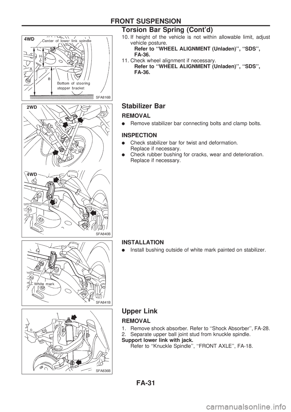
10. If height of the vehicle is not within allowable limit, adjust
vehicle posture.
Refer to ``WHEEL ALIGNMENT (Unladen)'', ``SDS'',
FA-36.
11. Check wheel alignment if necessary.
Refer to ``WHEEL ALIGNMENT (Unladen)'', ``SDS'',
FA-36.
Stabilizer Bar
REMOVAL
lRemove stabilizer bar connecting bolts and clamp bolts.
INSPECTION
lCheck stabilizer bar for twist and deformation.
Replace if necessary.
lCheck rubber bushing for cracks, wear and deterioration.
Replace if necessary.
INSTALLATION
lInstall bushing outside of white mark painted on stabilizer.
Upper Link
REMOVAL
1. Remove shock absorber. Refer to ``Shock Absorber'', FA-28.
2. Separate upper ball joint stud from knuckle spindle.
Support lower link with jack.
Refer to ``Knuckle Spindle'', ``FRONT AXLE'', FA-18.
SFA816B
SFA840B
SFA841B
SFA836B
FRONT SUSPENSION
Torsion Bar Spring (Cont'd)
FA-31
Page 797 of 1659
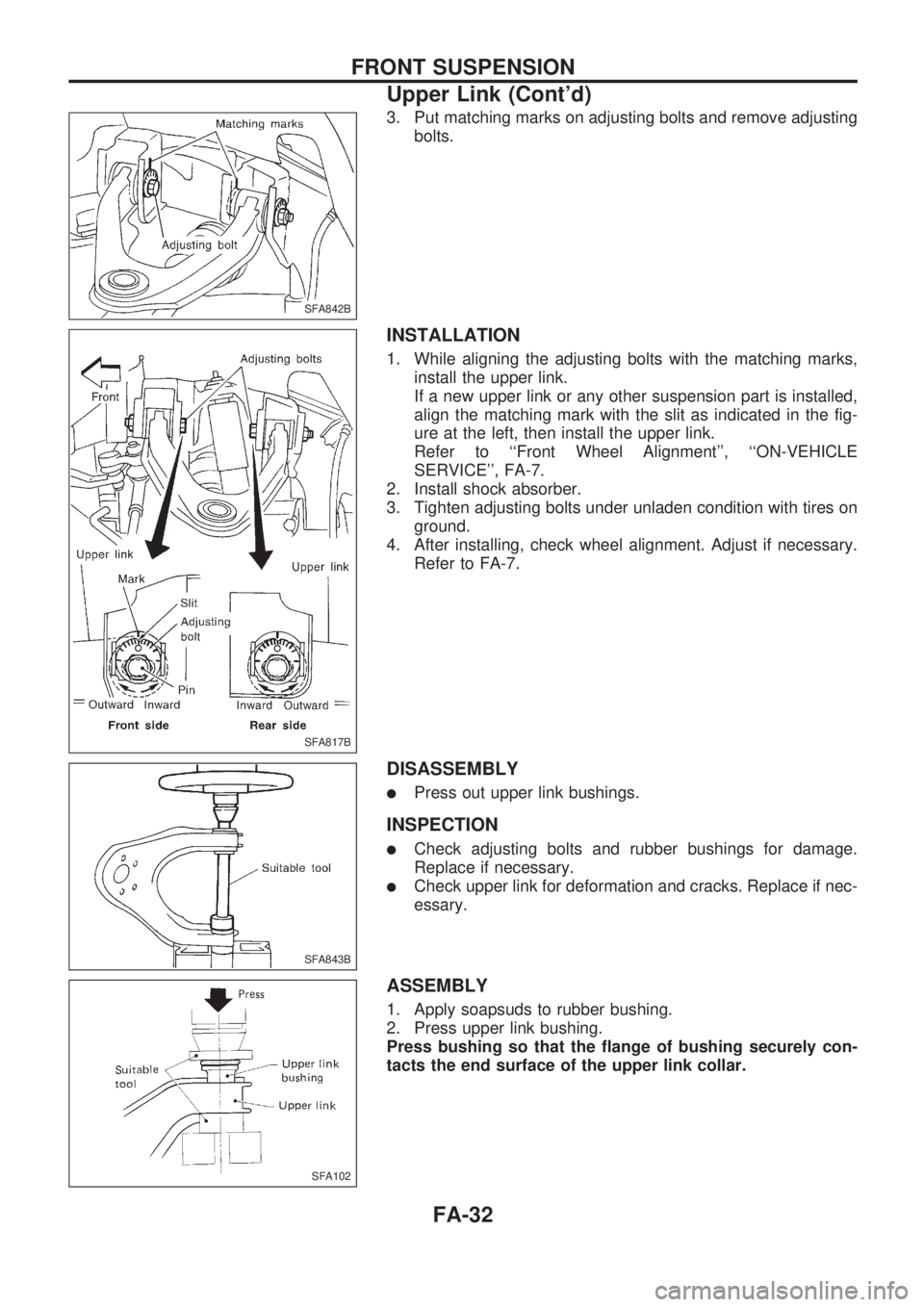
3. Put matching marks on adjusting bolts and remove adjusting
bolts.
INSTALLATION
1. While aligning the adjusting bolts with the matching marks,
install the upper link.
If a new upper link or any other suspension part is installed,
align the matching mark with the slit as indicated in the fig-
ure at the left, then install the upper link.
Refer to ``Front Wheel Alignment'', ``ON-VEHICLE
SERVICE'', FA-7.
2. Install shock absorber.
3. Tighten adjusting bolts under unladen condition with tires on
ground.
4. After installing, check wheel alignment. Adjust if necessary.
Refer to FA-7.
DISASSEMBLY
lPress out upper link bushings.
INSPECTION
lCheck adjusting bolts and rubber bushings for damage.
Replace if necessary.
lCheck upper link for deformation and cracks. Replace if nec-
essary.
ASSEMBLY
1. Apply soapsuds to rubber bushing.
2. Press upper link bushing.
Press bushing so that the flange of bushing securely con-
tacts the end surface of the upper link collar.
SFA842B
SFA817B
SFA843B
SFA102
FRONT SUSPENSION
Upper Link (Cont'd)
FA-32
Page 798 of 1659
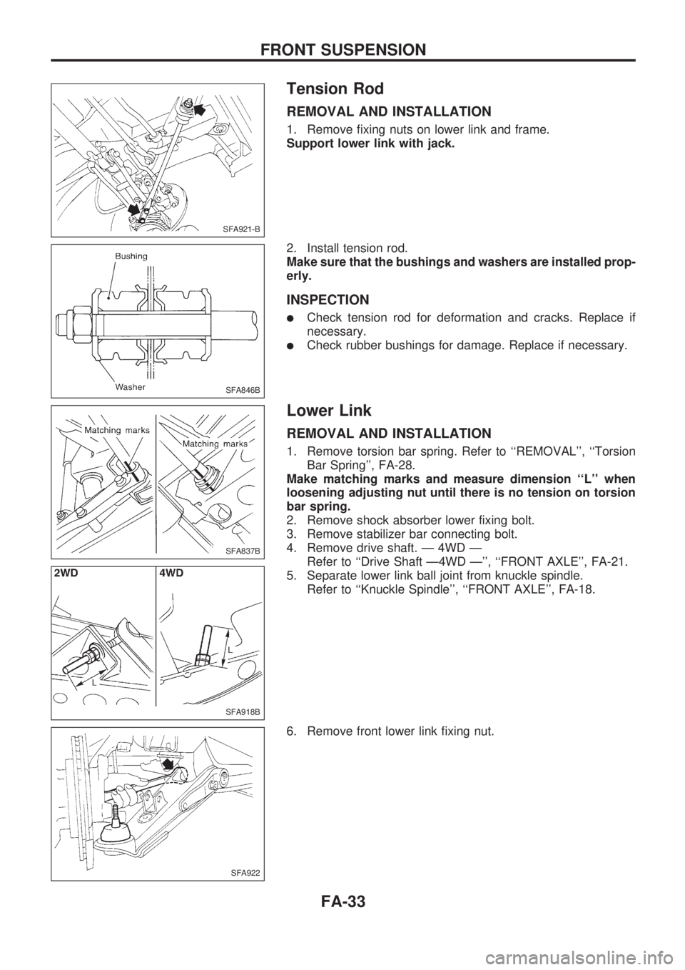
Tension Rod
REMOVAL AND INSTALLATION
1. Remove fixing nuts on lower link and frame.
Support lower link with jack.
2. Install tension rod.
Make sure that the bushings and washers are installed prop-
erly.
INSPECTION
lCheck tension rod for deformation and cracks. Replace if
necessary.
lCheck rubber bushings for damage. Replace if necessary.
Lower Link
REMOVAL AND INSTALLATION
1. Remove torsion bar spring. Refer to ``REMOVAL'', ``Torsion
Bar Spring'', FA-28.
Make matching marks and measure dimension ``L'' when
loosening adjusting nut until there is no tension on torsion
bar spring.
2. Remove shock absorber lower fixing bolt.
3. Remove stabilizer bar connecting bolt.
4. Remove drive shaft. Ð 4WD Ð
Refer to ``Drive Shaft Ð4WD Ð'', ``FRONT AXLE'', FA-21.
5. Separate lower link ball joint from knuckle spindle.
Refer to ``Knuckle Spindle'', ``FRONT AXLE'', FA-18.
6. Remove front lower link fixing nut.
SFA921-B
SFA846B
SFA837B
SFA918B
SFA922
FRONT SUSPENSION
FA-33
Page 799 of 1659
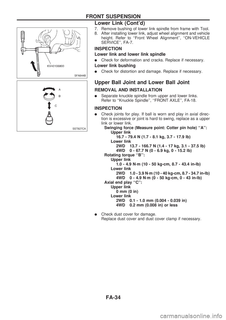
7. Remove bushing of lower link spindle from frame with Tool.
8. After installing lower link, adjust wheel alignment and vehicle
height. Refer to ``Front Wheel Alignment'', ``ON-VEHICLE
SERVICE'', FA-7.
INSPECTION
Lower link and lower link spindle
lCheck for deformation and cracks. Replace if necessary.
Lower link bushing
lCheck for distortion and damage. Replace if necessary.
Upper Ball Joint and Lower Ball Joint
REMOVAL AND INSTALLATION
lSeparate knuckle spindle from upper and lower links.
Refer to ``Knuckle Spindle'', ``FRONT AXLE'', FA-18.
INSPECTION
lCheck joints for play. If ball is worn and play in axial direc-
tion is excessive or joint is hard to swing, replace as a upper
link or lower link.
Swinging force (Measure point: Cotter pin hole) ``A'':
Upper link
16.7 - 79.4 N (1.7 - 8.1 kg, 3.7 - 17.9 lb)
Lower link
2WD 13.7 - 166.7 N (1.4 - 17 kg, 3.1 - 37.5 lb)
4WD 0 - 67.7 N (0 - 6.9 kg, 0 - 15.2 lb)
Rotating torque ``B'':
Upper link
1.0 - 4.9 N´m (10 - 50 kg-cm, 8.7 - 43.4 in-lb)
Lower link
2WD 1.0 - 3.9 N´m (10 - 40 kg-cm, 8.7 - 34.7 in-lb)
4WD 0 - 4.9 N´m (0 - 50 kg-cm,0-43in-lb)
Axial end play ``C'':
Upper link
0mm(0in)
Lower link
2WD 0.1 - 1.0 mm (0.004 - 0.039 in)
4WD 0.2 mm (0.008 in) or less
lCheck dust cover for damage.
Replace dust cover and dust cover clamp if necessary.
SFA844B
SST827CA
FRONT SUSPENSION
Lower Link (Cont'd)
FA-34
Page 800 of 1659
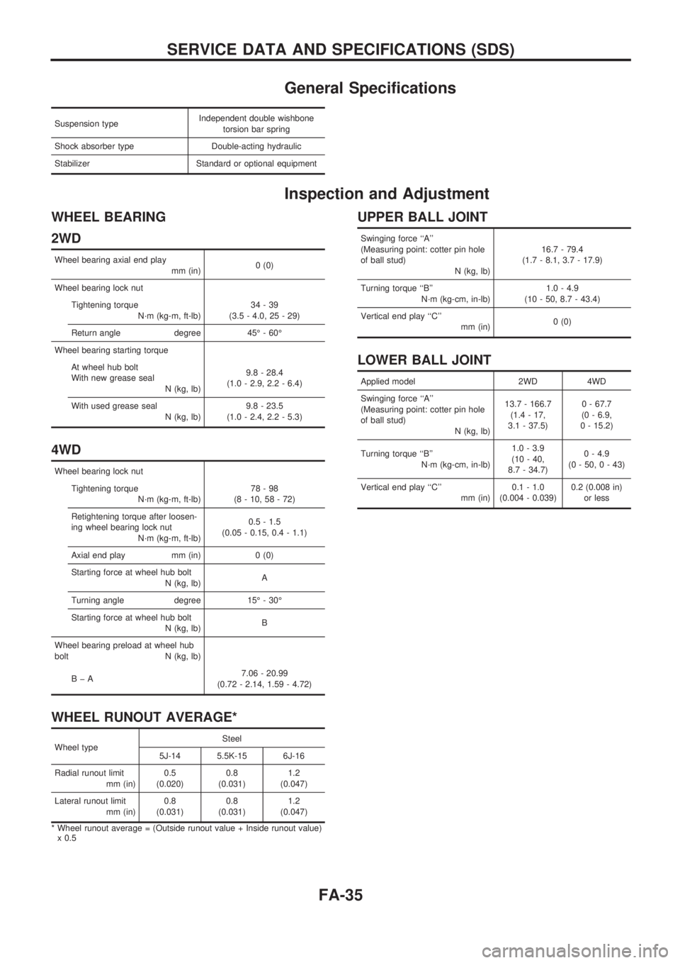
General Specifications
Suspension typeIndependent double wishbone
torsion bar spring
Shock absorber type Double-acting hydraulic
Stabilizer Standard or optional equipment
Inspection and Adjustment
WHEEL BEARING
2WD
Wheel bearing axial end play
mm (in)0 (0)
Wheel bearing lock nut
Tightening torque
N´m (kg-m, ft-lb)34-39
(3.5 - 4.0, 25 - 29)
Return angle degree 45É - 60É
Wheel bearing starting torque
At wheel hub bolt
With new grease seal
N (kg, lb)9.8 - 28.4
(1.0 - 2.9, 2.2 - 6.4)
With used grease seal
N (kg, lb)9.8 - 23.5
(1.0 - 2.4, 2.2 - 5.3)
4WD
Wheel bearing lock nut
Tightening torque
N´m (kg-m, ft-lb)78-98
(8 - 10, 58 - 72)
Retightening torque after loosen-
ing wheel bearing lock nut
N´m (kg-m, ft-lb)0.5 - 1.5
(0.05 - 0.15, 0.4 - 1.1)
Axial end play mm (in) 0 (0)
Starting force at wheel hub bolt
N (kg, lb)A
Turning angle degree 15É - 30É
Starting force at wheel hub bolt
N (kg, lb)B
Wheel bearing preload at wheel hub
bolt N (kg, lb)
BþA7.06 - 20.99
(0.72 - 2.14, 1.59 - 4.72)
WHEEL RUNOUT AVERAGE*
Wheel typeSteel
5J-14 5.5K-15 6J-16
Radial runout limit
mm (in)0.5
(0.020)0.8
(0.031)1.2
(0.047)
Lateral runout limit
mm (in)0.8
(0.031)0.8
(0.031)1.2
(0.047)
* Wheel runout average = (Outside runout value + Inside runout value)
x 0.5
UPPER BALL JOINT
Swinging force ``A''
(Measuring point: cotter pin hole
of ball stud)
N (kg, lb)16.7 - 79.4
(1.7 - 8.1, 3.7 - 17.9)
Turning torque ``B''
N´m (kg-cm, in-lb)1.0 - 4.9
(10 - 50, 8.7 - 43.4)
Vertical end play ``C''
mm (in)0 (0)
LOWER BALL JOINT
Applied model 2WD 4WD
Swinging force ``A''
(Measuring point: cotter pin hole
of ball stud)
N (kg, lb)13.7 - 166.7
(1.4 - 17,
3.1 - 37.5)0 - 67.7
(0 - 6.9,
0 - 15.2)
Turning torque ``B''
N´m (kg-cm, in-lb)1.0 - 3.9
(10 - 40,
8.7 - 34.7)0 - 4.9
(0 - 50, 0 - 43)
Vertical end play ``C''
mm (in)0.1 - 1.0
(0.004 - 0.039)0.2 (0.008 in)
or less
SERVICE DATA AND SPECIFICATIONS (SDS)
FA-35