NISSAN PRIMERA 1999 Electronic Repair Manual
Manufacturer: NISSAN, Model Year: 1999, Model line: PRIMERA, Model: NISSAN PRIMERA 1999Pages: 2267, PDF Size: 35.74 MB
Page 1561 of 2267
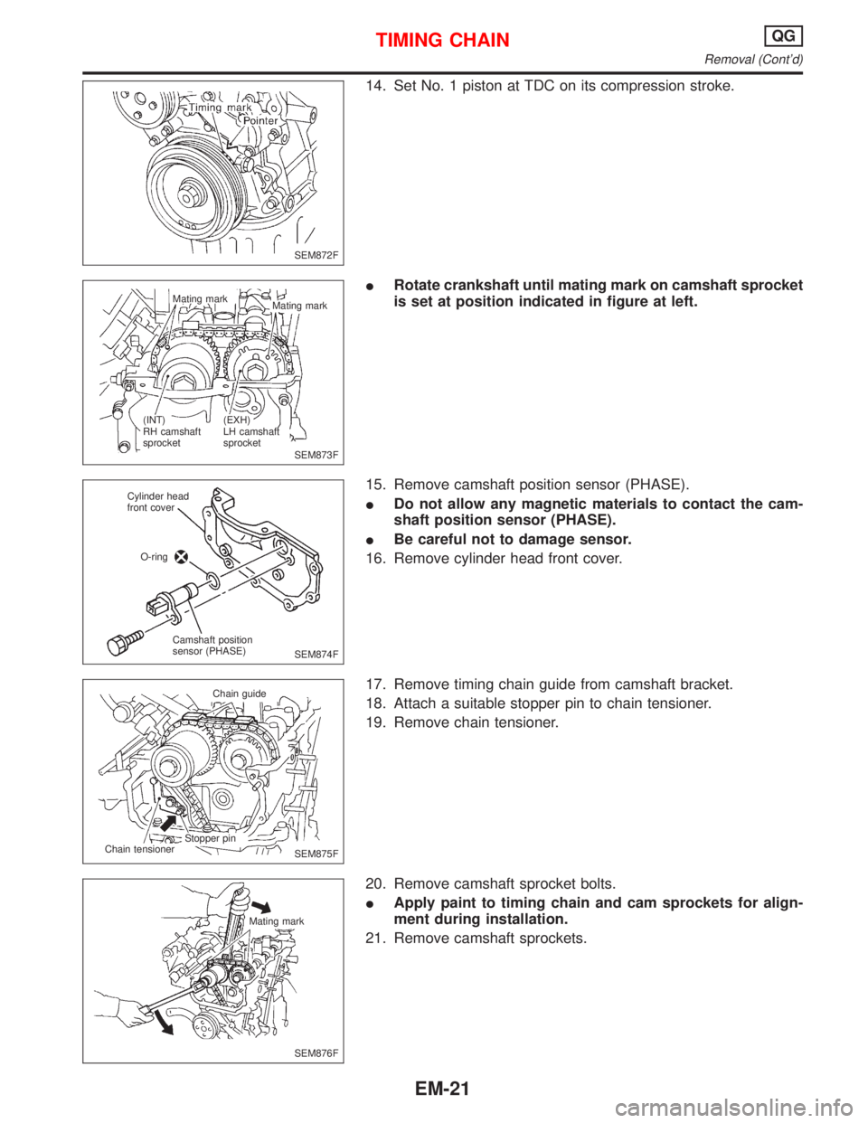
14. Set No. 1 piston at TDC on its compression stroke.
IRotate crankshaft until mating mark on camshaft sprocket
is set at position indicated in figure at left.
15. Remove camshaft position sensor (PHASE).
IDo not allow any magnetic materials to contact the cam-
shaft position sensor (PHASE).
IBe careful not to damage sensor.
16. Remove cylinder head front cover.
17. Remove timing chain guide from camshaft bracket.
18. Attach a suitable stopper pin to chain tensioner.
19. Remove chain tensioner.
20. Remove camshaft sprocket bolts.
IApply paint to timing chain and cam sprockets for align-
ment during installation.
21. Remove camshaft sprockets.
SEM872F
SEM873F Mating mark
Mating mark
(INT)
RH camshaft
sprocket(EXH)
LH camshaft
sprocket
SEM874F Cylinder head
front cover
O-ring
Camshaft position
sensor (PHASE)
SEM875F Chain guide
Stopper pin
Chain tensioner
SEM876F Mating mark
TIMING CHAINQG
Removal (Cont'd)
EM-21
Page 1562 of 2267
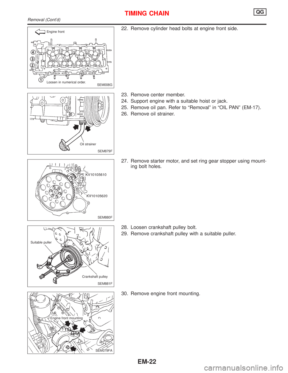
22. Remove cylinder head bolts at engine front side.
23. Remove center member.
24. Support engine with a suitable hoist or jack.
25. Remove oil pan. Refer to ªRemovalº in ªOIL PANº (EM-17).
26. Remove oil strainer.
27. Remove starter motor, and set ring gear stopper using mount-
ing bolt holes.
28. Loosen crankshaft pulley bolt.
29. Remove crankshaft pulley with a suitable puller.
30. Remove engine front mounting.
SEM008G Engine front
Loosen in numerical order.
SEM879F Oil strainer
SEM880F
SEM881F Suitable puller
Crankshaft pulley
SEM079FA Engine front mounting
TIMING CHAINQG
Removal (Cont'd)
EM-22
Page 1563 of 2267
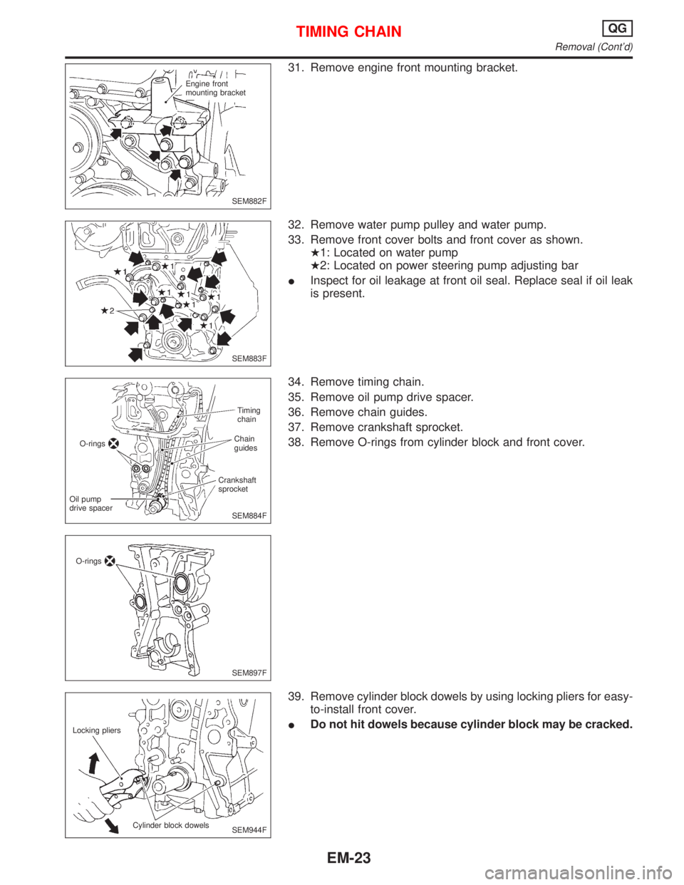
31. Remove engine front mounting bracket.
32. Remove water pump pulley and water pump.
33. Remove front cover bolts and front cover as shown.
H1: Located on water pump
H2: Located on power steering pump adjusting bar
IInspect for oil leakage at front oil seal. Replace seal if oil leak
is present.
34. Remove timing chain.
35. Remove oil pump drive spacer.
36. Remove chain guides.
37. Remove crankshaft sprocket.
38. Remove O-rings from cylinder block and front cover.
39. Remove cylinder block dowels by using locking pliers for easy-
to-install front cover.
IDo not hit dowels because cylinder block may be cracked.
SEM882F Engine front
mounting bracket
SEM883F
SEM884FTiming
chain
Chain
guides
Crankshaft
sprocket
Oil pump
drive spacerO-rings
SEM897F O-rings
SEM944F Locking pliers
Cylinder block dowels
TIMING CHAINQG
Removal (Cont'd)
EM-23
Page 1564 of 2267
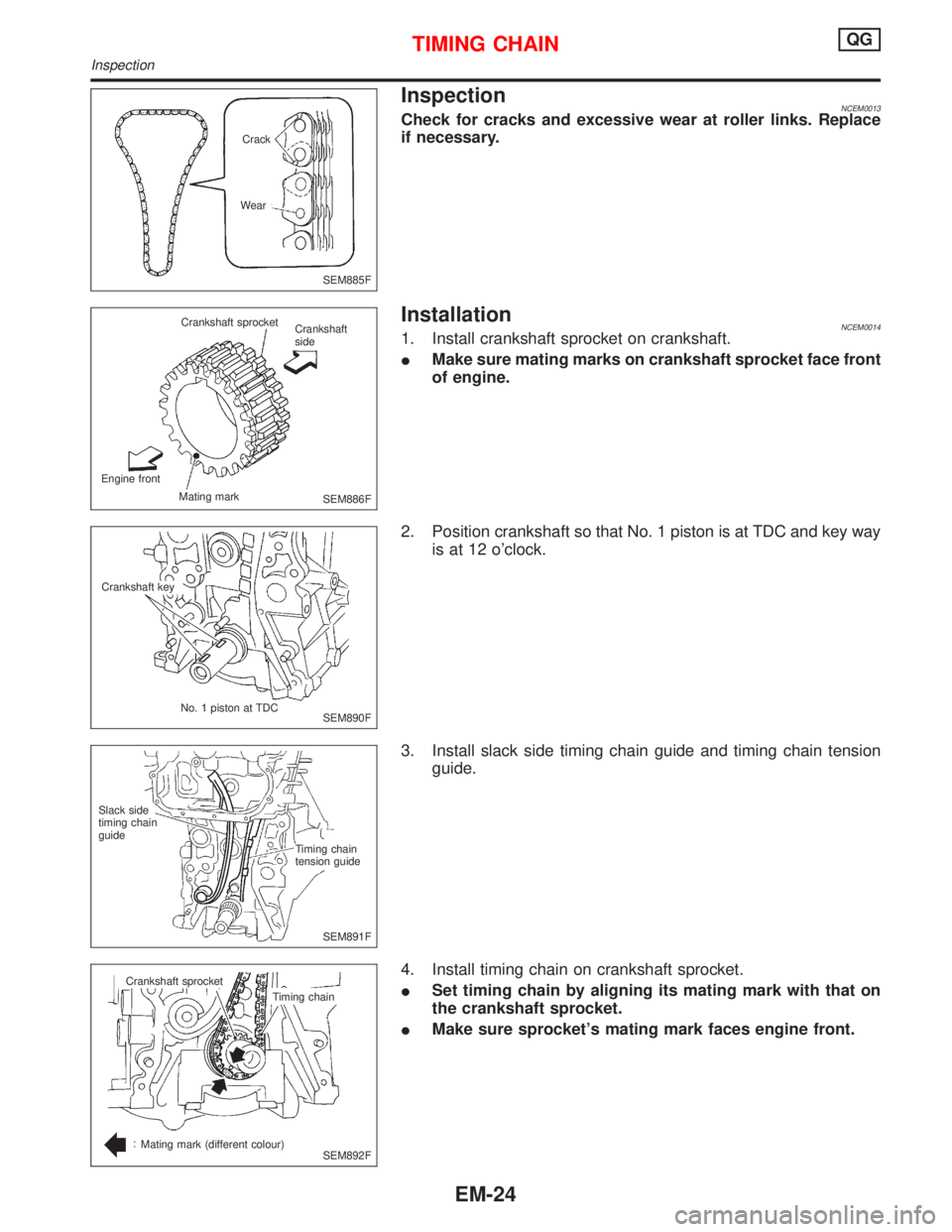
InspectionNCEM0013Check for cracks and excessive wear at roller links. Replace
if necessary.
InstallationNCEM00141. Install crankshaft sprocket on crankshaft.
IMake sure mating marks on crankshaft sprocket face front
of engine.
2. Position crankshaft so that No. 1 piston is at TDC and key way
is at 12 o'clock.
3. Install slack side timing chain guide and timing chain tension
guide.
4. Install timing chain on crankshaft sprocket.
ISet timing chain by aligning its mating mark with that on
the crankshaft sprocket.
IMake sure sprocket's mating mark faces engine front.
SEM885F Crack
Wear
SEM886F Crankshaft sprocket
Crankshaft
side
Engine front
Mating mark
SEM890F Crankshaft key
No. 1 piston at TDC
SEM891F Timing chain
tension guide Slack side
timing chain
guide
SEM892F Crankshaft sprocket
Timing chain
Mating mark (different colour)
TIMING CHAINQG
Inspection
EM-24
Page 1565 of 2267
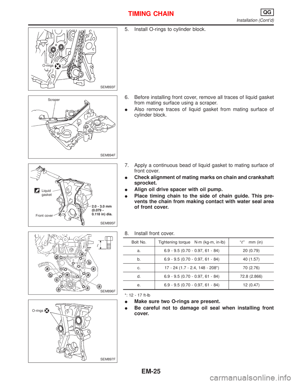
5. Install O-rings to cylinder block.
6. Before installing front cover, remove all traces of liquid gasket
from mating surface using a scraper.
IAlso remove traces of liquid gasket from mating surface of
cylinder block.
7. Apply a continuous bead of liquid gasket to mating surface of
front cover.
ICheck alignment of mating marks on chain and crankshaft
sprocket.
IAlign oil drive spacer with oil pump.
IPlace timing chain to the side of chain guide. This pre-
vents the chain from making contact with water seal area
of front cover.
8. Install front cover.
Bolt No. Tightening torque N×m (kg-m, in-lb) ªº mm (in)
a. 6.9 - 9.5 (0.70 - 0.97, 61 - 84) 20 (0.79)
b. 6.9 - 9.5 (0.70 - 0.97, 61 - 84) 40 (1.57)
c. 17 - 24 (1.7 - 2.4, 148 - 208*) 70 (2.76)
d. 6.9 - 9.5 (0.70 - 0.97, 61 - 84) 72.8 (2.866)
e. 6.9 - 9.5 (0.70 - 0.97, 61 - 84) 12 (0.47)
*: 12 - 17 ft-lb
IMake sure two O-rings are present.
IBe careful not to damage oil seal when installing front
cover.
SEM893F O-rings
SEM894F Scraper
SEM895F 2.0 - 3.0 mm
(0.079 -
0.118 in) dia.
Liquid
gasket
Front cover
SEM896F
SEM897F O-rings
TIMING CHAINQG
Installation (Cont'd)
EM-25
Page 1566 of 2267
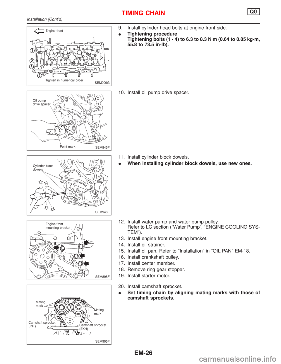
9. Install cylinder head bolts at engine front side.
ITightening procedure
Tightening bolts (1 - 4) to 6.3 to 8.3 N×m (0.64 to 0.85 kg-m,
55.8 to 73.5 in-lb).
10. Install oil pump drive spacer.
11. Install cylinder block dowels.
IWhen installing cylinder block dowels, use new ones.
12. Install water pump and water pump pulley.
Refer to LC section (ªWater Pumpº, ªENGINE COOLING SYS-
TEMº).
13. Install engine front mounting bracket.
14. Install oil strainer.
15. Install oil pan. Refer to ªInstallationº in ªOIL PANº EM-18.
16. Install crankshaft pulley.
17. Install center member.
18. Remove ring gear stopper.
19. Install starter motor.
20. Install camshaft sprocket.
ISet timing chain by aligning mating marks with those of
camshaft sprockets.
SEM009G Engine front
Tighten in numerical order
SEM945F Oil pump
drive spacer
Point mark
SEM946F Cylinder block
dowels
SEM898F Engine front
mounting bracket
SEM905F Mating
mark
Camshaft sprocket
(INT)Mating
mark
Camshaft sprocket
(EXH)
TIMING CHAINQG
Installation (Cont'd)
EM-26
Page 1567 of 2267
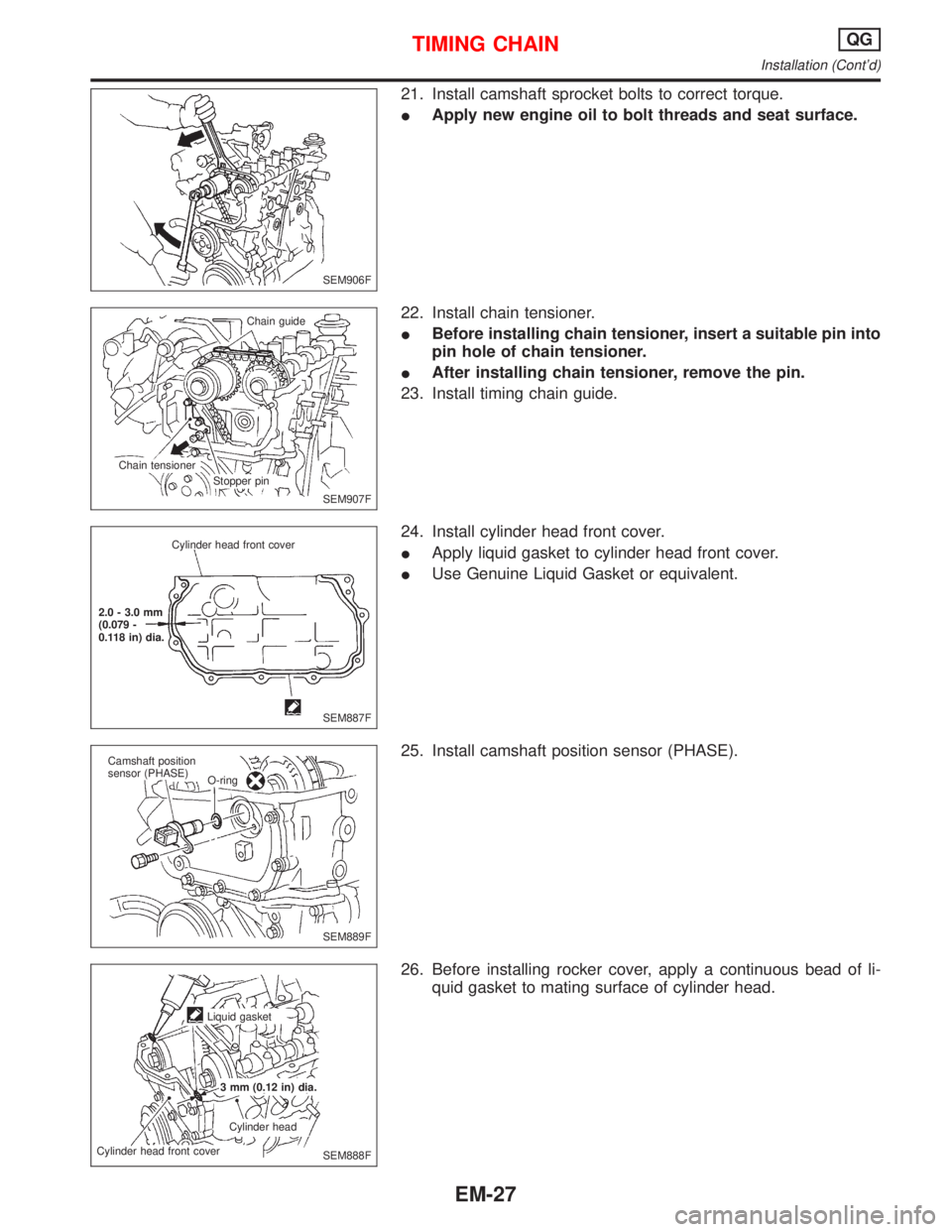
21. Install camshaft sprocket bolts to correct torque.
IApply new engine oil to bolt threads and seat surface.
22. Install chain tensioner.
IBefore installing chain tensioner, insert a suitable pin into
pin hole of chain tensioner.
IAfter installing chain tensioner, remove the pin.
23. Install timing chain guide.
24. Install cylinder head front cover.
IApply liquid gasket to cylinder head front cover.
IUse Genuine Liquid Gasket or equivalent.
25. Install camshaft position sensor (PHASE).
26. Before installing rocker cover, apply a continuous bead of li-
quid gasket to mating surface of cylinder head.
SEM906F
SEM907F Chain guide
Chain tensioner
Stopper pin
SEM887F Cylinder head front cover
2.0 - 3.0 mm
(0.079 -
0.118 in) dia.
SEM889F Camshaft position
sensor (PHASE)
O-ring
SEM888F Liquid gasket
3 mm (0.12 in) dia.
Cylinder head
Cylinder head front cover
TIMING CHAINQG
Installation (Cont'd)
EM-27
Page 1568 of 2267
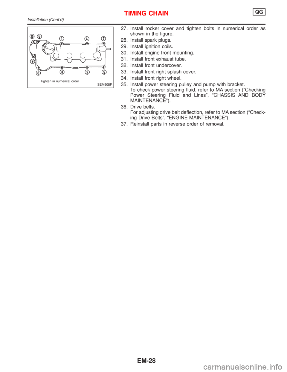
27. Install rocker cover and tighten bolts in numerical order as
shown in the figure.
28. Install spark plugs.
29. Install ignition coils.
30. Install engine front mounting.
31. Install front exhaust tube.
32. Install front undercover.
33. Install front right splash cover.
34. Install front right wheel.
35. Install power steering pulley and pump with bracket.
To check power steering fluid, refer to MA section (ªChecking
Power Steering Fluid and Linesº, ªCHASSIS AND BODY
MAINTENANCEº).
36. Drive belts.
For adjusting drive belt deflection, refer to MA section (ªCheck-
ing Drive Beltsº, ªENGINE MAINTENANCEº).
37. Reinstall parts in reverse order of removal.
SEM908F Tighten in numerical order
TIMING CHAINQG
Installation (Cont'd)
EM-28
Page 1569 of 2267
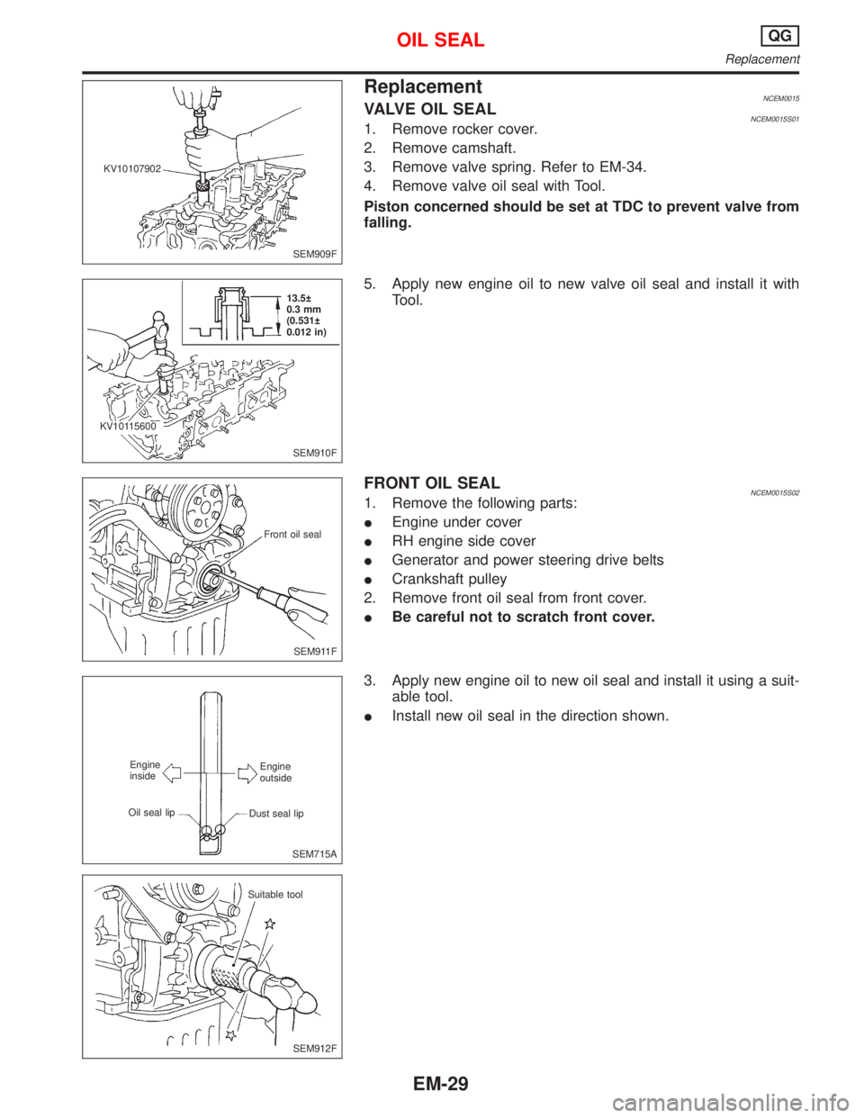
ReplacementNCEM0015VALVE OIL SEALNCEM0015S011. Remove rocker cover.
2. Remove camshaft.
3. Remove valve spring. Refer to EM-34.
4. Remove valve oil seal with Tool.
Piston concerned should be set at TDC to prevent valve from
falling.
5. Apply new engine oil to new valve oil seal and install it with
Tool.
FRONT OIL SEALNCEM0015S021. Remove the following parts:
IEngine under cover
IRH engine side cover
IGenerator and power steering drive belts
ICrankshaft pulley
2. Remove front oil seal from front cover.
IBe careful not to scratch front cover.
3. Apply new engine oil to new oil seal and install it using a suit-
able tool.
IInstall new oil seal in the direction shown.
SEM909F KV10107902
SEM910F 13.5
0.3 mm
(0.531
0.012 in)
KV10115600
SEM911F Front oil seal
SEM715A Engine
outside
Dust seal lip Engine
inside
Oil seal lip
SEM912F Suitable tool
OIL SEALQG
Replacement
EM-29
Page 1570 of 2267
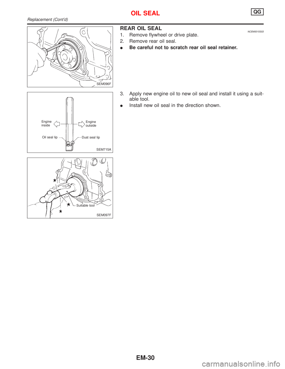
REAR OIL SEALNCEM0015S031. Remove flywheel or drive plate.
2. Remove rear oil seal.
IBe careful not to scratch rear oil seal retainer.
3. Apply new engine oil to new oil seal and install it using a suit-
able tool.
IInstall new oil seal in the direction shown.
SEM096F
SEM715A Engine
outside
Dust seal lip Oil seal lip Engine
inside
SEM097F Suitable tool
OIL SEALQG
Replacement (Cont'd)
EM-30