NISSAN PRIMERA 1999 Electronic Repair Manual
Manufacturer: NISSAN, Model Year: 1999, Model line: PRIMERA, Model: NISSAN PRIMERA 1999Pages: 2267, PDF Size: 35.74 MB
Page 1581 of 2267
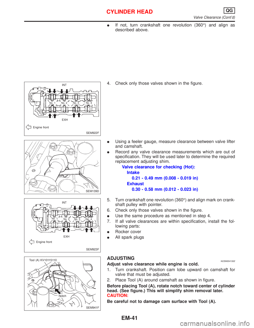
IIf not, turn crankshaft one revolution (360É) and align as
described above.
4. Check only those valves shown in the figure.
IUsing a feeler gauge, measure clearance between valve lifter
and camshaft.
IRecord any valve clearance measurements which are out of
specification. They will be used later to determine the required
replacement adjusting shim.
Valve clearance for checking (Hot):
Intake
0.21 - 0.49 mm (0.008 - 0.019 in)
Exhaust
0.30 - 0.58 mm (0.012 - 0.023 in)
5. Turn crankshaft one revolution (360É) and align mark on crank-
shaft pulley with pointer.
6. Check only those valves shown in the figure.
IUse the same procedure as mentioned in step 4.
7. If all valve clearances are within specification, install the fol-
lowing parts:
IRocker cover
IAll spark plugs
ADJUSTINGNCEM0041S02Adjust valve clearance while engine is cold.
1. Turn crankshaft. Position cam lobe upward on camshaft for
valve that must be adjusted.
2. Place Tool (A) around camshaft as shown in figure.
Before placing Tool (A), rotate notch toward center of cylinder
head. (See figure.) This will simplify shim removal later.
CAUTION:
Be careful not to damage cam surface with Tool (A).
SEM922F INT
EXH
Engine front
No. 4 No. 3 No. 2 No. 1
.SEM139D
SEM923F INT
EXH
Engine front
No. 1
No. 2
No. 3 No. 4
SEM941F Tool (A) KV10115110
Notch
CYLINDER HEADQG
Valve Clearance (Cont'd)
EM-41
Page 1582 of 2267
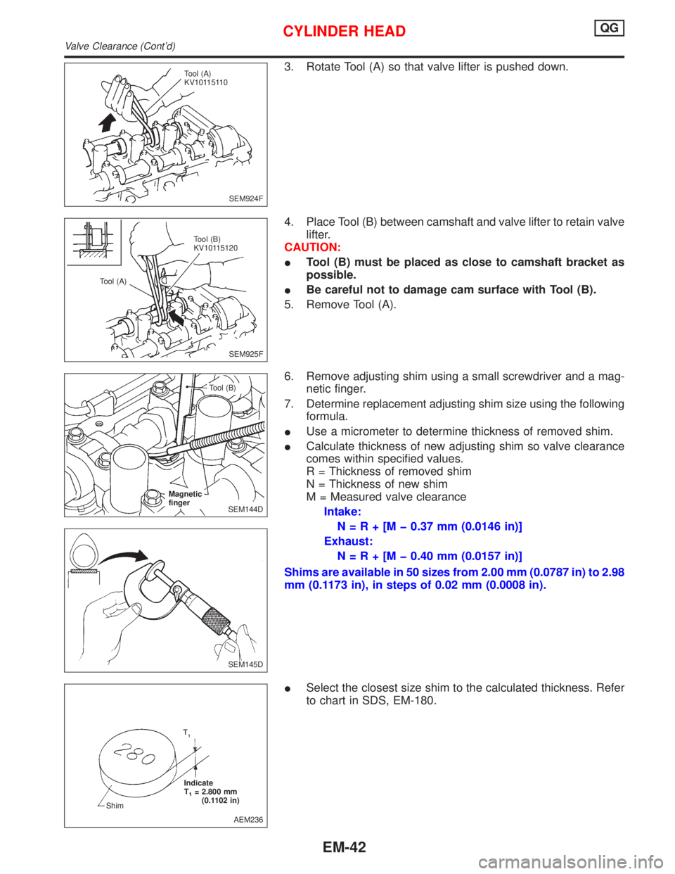
3. Rotate Tool (A) so that valve lifter is pushed down.
4. Place Tool (B) between camshaft and valve lifter to retain valve
lifter.
CAUTION:
ITool (B) must be placed as close to camshaft bracket as
possible.
IBe careful not to damage cam surface with Tool (B).
5. Remove Tool (A).
6. Remove adjusting shim using a small screwdriver and a mag-
netic finger.
7. Determine replacement adjusting shim size using the following
formula.
IUse a micrometer to determine thickness of removed shim.
ICalculate thickness of new adjusting shim so valve clearance
comes within specified values.
R = Thickness of removed shim
N = Thickness of new shim
M = Measured valve clearance
Intake:
N=R+[Mþ0.37 mm (0.0146 in)]
Exhaust:
N=R+[Mþ0.40 mm (0.0157 in)]
Shims are available in 50 sizes from 2.00 mm (0.0787 in) to 2.98
mm (0.1173 in), in steps of 0.02 mm (0.0008 in).
ISelect the closest size shim to the calculated thickness. Refer
to chart in SDS, EM-180.
SEM924F Tool (A)
KV10115110
SEM925F Tool (B)
KV10115120
Tool (A)
SEM144D Magnetic
finger
.Tool (B)
SEM145D
AEM236 Indicate
T
1= 2.800 mm
(0.1102 in)
Shim
CYLINDER HEADQG
Valve Clearance (Cont'd)
EM-42
Page 1583 of 2267
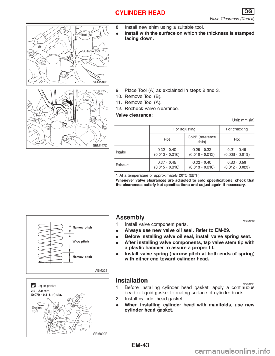
8. Install new shim using a suitable tool.
IInstall with the surface on which the thickness is stamped
facing down.
9. Place Tool (A) as explained in steps 2 and 3.
10. Remove Tool (B).
11. Remove Tool (A).
12. Recheck valve clearance.
Valve clearance:
Unit: mm (in)
For adjusting For checking
HotCold* (reference
data)Hot
Intake0.32 - 0.40
(0.013 - 0.016)0.25 - 0.33
(0.010 - 0.013)0.21 - 0.49
(0.008 - 0.019)
Exhaust0.37 - 0.45
(0.015 - 0.018)0.32 - 0.40
(0.013 - 0.016)0.30 - 0.58
(0.012 - 0.023)
*: At a temperature of approximately 20ÉC (68ÉF)
Whenever valve clearances are adjusted to cold specifications, check that
the clearances satisfy hot specifications and adjust again if necessary.
AssemblyNCEM00201. Install valve component parts.
IAlways use new valve oil seal. Refer to EM-29.
IBefore installing valve oil seal, install valve spring seat.
IAfter installing valve components, tap valve stem tip with
a plastic hammer to assure a proper fit.
IInstall valve spring (narrow pitch at both ends of spring)
with either end toward cylinder head.
InstallationNCEM00211. Before installing cylinder head gasket, apply a continuous
bead of liquid gasket to mating surface of cylinder block.
2. Install cylinder head gasket.
IWhen installing cylinder head with manifolds, use new
cylinder head gasket.
SEM146D Tool (B)
Suitable tool
SEM147D Tool (B)
Tool (A)
AEM293 Narrow pitch
Wide pitch
Narrow pitch
SEM899F
Liquid gasket
2.0 - 3.0 mm
(0.079 - 0.118 in) dia.
Engine
front
CYLINDER HEADQG
Valve Clearance (Cont'd)
EM-43
Page 1584 of 2267
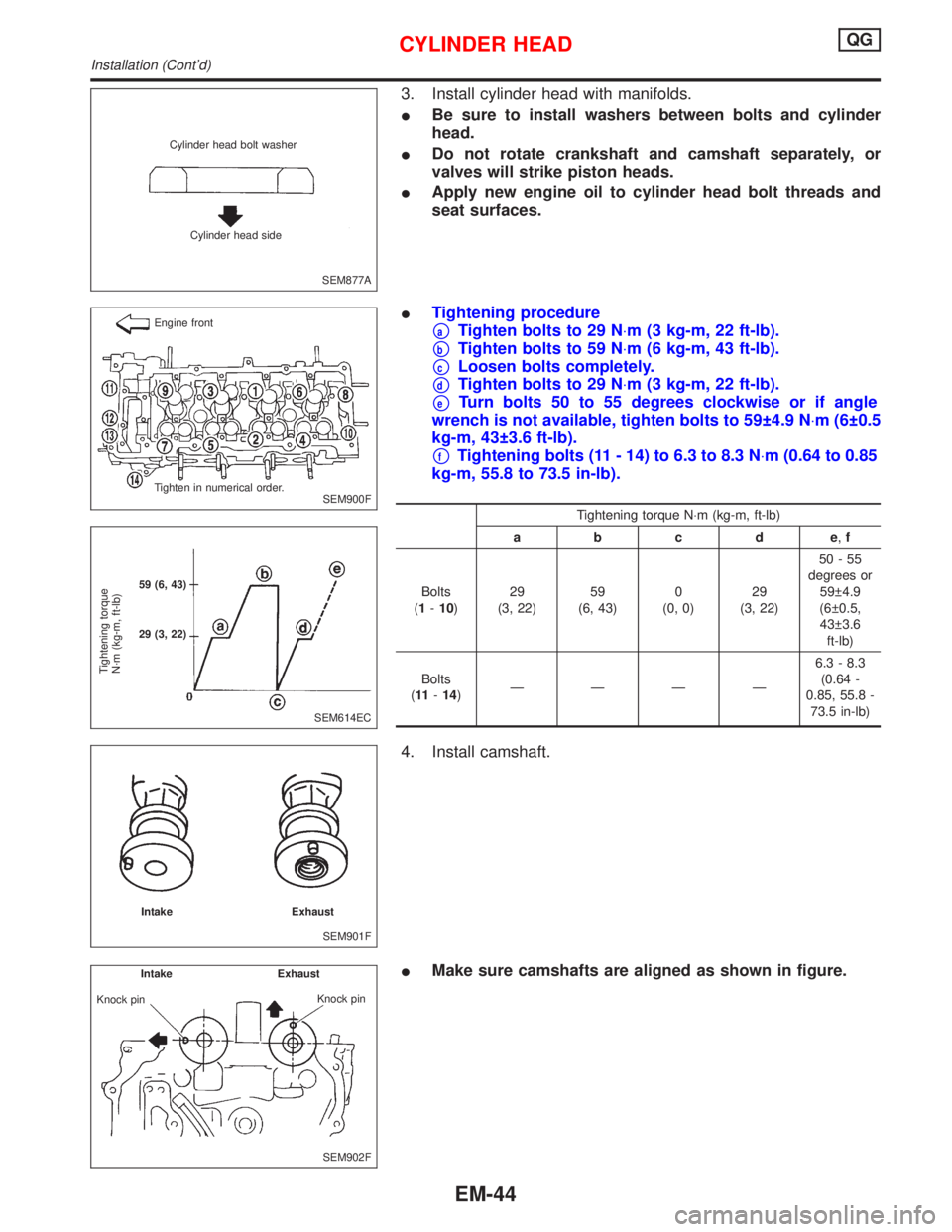
3. Install cylinder head with manifolds.
IBe sure to install washers between bolts and cylinder
head.
IDo not rotate crankshaft and camshaft separately, or
valves will strike piston heads.
IApply new engine oil to cylinder head bolt threads and
seat surfaces.
ITightening procedure
paTighten bolts to 29 N×m (3 kg-m, 22 ft-lb).
pbTighten bolts to 59 N×m (6 kg-m, 43 ft-lb).
pcLoosen bolts completely.
pdTighten bolts to 29 N×m (3 kg-m, 22 ft-lb).
peTurn bolts 50 to 55 degrees clockwise or if angle
wrench is not available, tighten bolts to 59 4.9 N×m (6 0.5
kg-m, 43 3.6 ft-lb).
pfTightening bolts (11 - 14) to 6.3 to 8.3 N×m (0.64 to 0.85
kg-m, 55.8 to 73.5 in-lb).
Tightening torque N×m (kg-m, ft-lb)
abcde,f
Bolts
(1-10)29
(3, 22)59
(6, 43)0
(0, 0)29
(3, 22)50-55
degrees or
59 4.9
(6 0.5,
43 3.6
ft-lb)
Bolts
(11-14)ÐÐÐÐ6.3 - 8.3
(0.64 -
0.85, 55.8 -
73.5 in-lb)
4. Install camshaft.
IMake sure camshafts are aligned as shown in figure.
SEM877A Cylinder head bolt washer
Cylinder head side
SEM900F Engine front
Tighten in numerical order.
SEM614EC
Tightening torque
N´m (kg-m, ft-lb)
59 (6, 43)
29 (3, 22)
SEM901F Intake Exhaust
SEM902F Intake Exhaust
Knock pin
Knock pin
CYLINDER HEADQG
Installation (Cont'd)
EM-44
Page 1585 of 2267
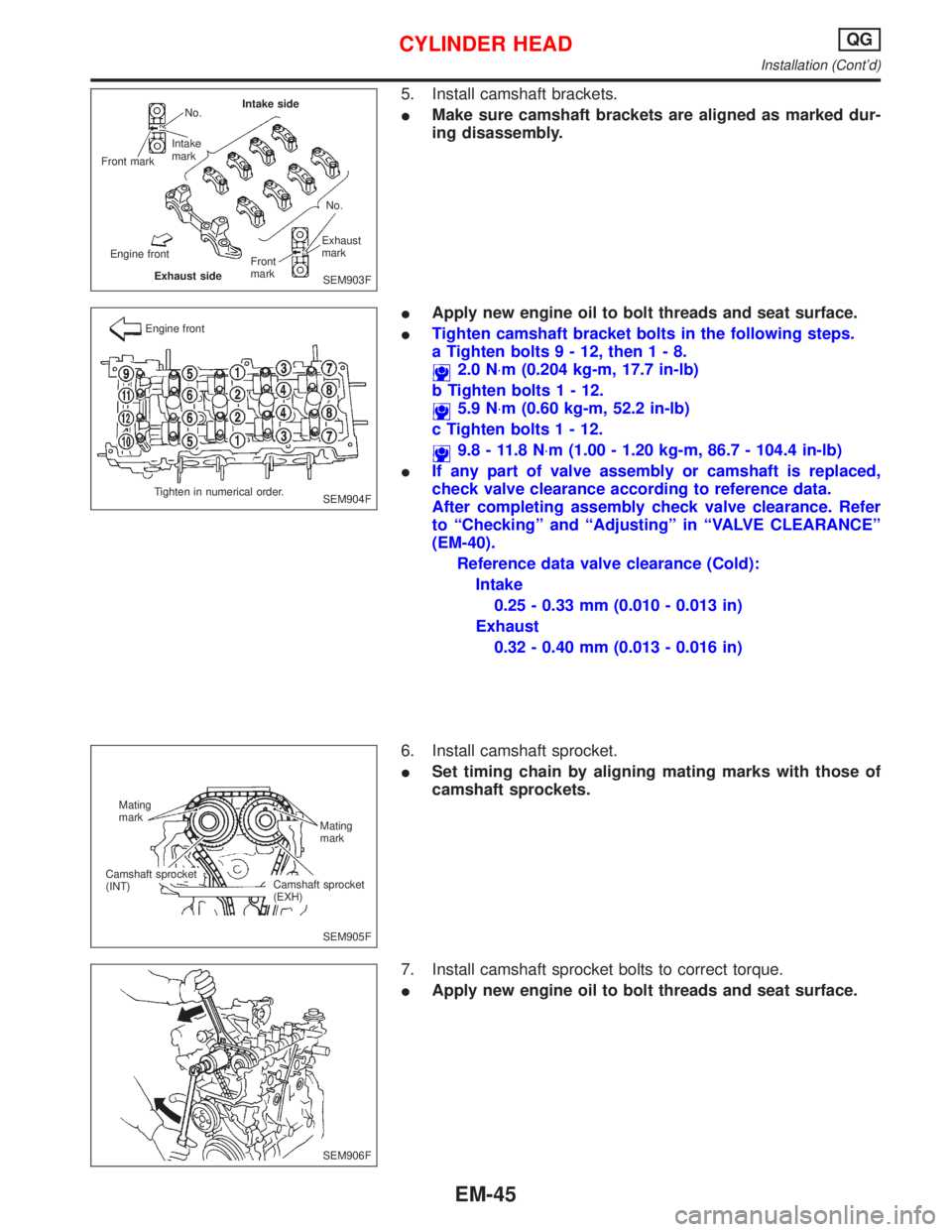
5. Install camshaft brackets.
IMake sure camshaft brackets are aligned as marked dur-
ing disassembly.
IApply new engine oil to bolt threads and seat surface.
ITighten camshaft bracket bolts in the following steps.
a Tighten bolts9-12,then1-8.
2.0 N×m (0.204 kg-m, 17.7 in-lb)
b Tighten bolts1-12.
5.9 N×m (0.60 kg-m, 52.2 in-lb)
c Tighten bolts1-12.
9.8 - 11.8 N×m (1.00 - 1.20 kg-m, 86.7 - 104.4 in-lb)
IIf any part of valve assembly or camshaft is replaced,
check valve clearance according to reference data.
After completing assembly check valve clearance. Refer
to ªCheckingº and ªAdjustingº in ªVALVE CLEARANCEº
(EM-40).
Reference data valve clearance (Cold):
Intake
0.25 - 0.33 mm (0.010 - 0.013 in)
Exhaust
0.32 - 0.40 mm (0.013 - 0.016 in)
6. Install camshaft sprocket.
ISet timing chain by aligning mating marks with those of
camshaft sprockets.
7. Install camshaft sprocket bolts to correct torque.
IApply new engine oil to bolt threads and seat surface.
SEM903F No.
Intake
mark
Front markIntake side
No.
Exhaust
mark
Front
mark
Exhaust side Engine front
SEM904F Engine front
Tighten in numerical order.
SEM905F Mating
mark
Mating
mark
Camshaft sprocket
(EXH) Camshaft sprocket
(INT)
SEM906F
CYLINDER HEADQG
Installation (Cont'd)
EM-45
Page 1586 of 2267
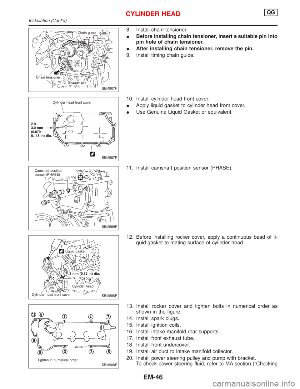
8. Install chain tensioner.
IBefore installing chain tensioner, insert a suitable pin into
pin hole of chain tensioner.
IAfter installing chain tensioner, remove the pin.
9. Install timing chain guide.
10. Install cylinder head front cover.
IApply liquid gasket to cylinder head front cover.
IUse Genuine Liquid Gasket or equivalent.
11. Install camshaft position sensor (PHASE).
12. Before installing rocker cover, apply a continuous bead of li-
quid gasket to mating surface of cylinder head.
13. Install rocker cover and tighten bolts in numerical order as
shown in the figure.
14. Install spark plugs.
15. Install ignition coils.
16. Install intake manifold rear supports.
17. Install front exhaust tube.
18. Install front undercover.
19. Install air duct to intake manifold collector.
20. Install power steering pulley and pump with bracket.
To check power steering fluid, refer to MA section (ªChecking
SEM907F Chain guide
Stopper pin Chain tensioner
SEM887F Cylinder head front cover
2.0 -
3.0 mm
(0.079 -
0.118 in) dia.
SEM889F Camshaft position
sensor (PHASE)
O-ring
SEM888F Liquid gasket
3 mm (0.12 in) dia.
Cylinder head
Cylinder head front cover
SEM908F Tighten in numerical order.
CYLINDER HEADQG
Installation (Cont'd)
EM-46
Page 1587 of 2267
Power Steering Fluid and Linesº, ªCHASSIS AND BODY
MAINTENANCEº).
21. Drive belts.
For adjusting drive belt deflection, refer to MA section (ªCheck-
ing Drive Beltsº, ªENGINE MAINTENANCEº).
22. Reinstall parts in reverse order of removal.
CYLINDER HEADQG
Installation (Cont'd)
EM-47
Page 1588 of 2267
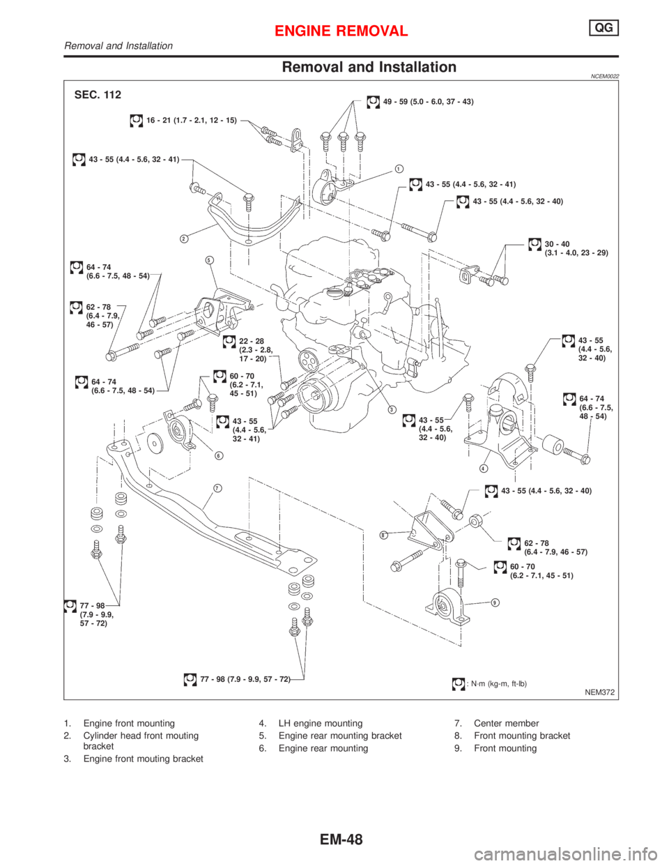
Removal and InstallationNCEM0022
1. Engine front mounting
2. Cylinder head front mouting
bracket
3. Engine front mouting bracket4. LH engine mounting
5. Engine rear mounting bracket
6. Engine rear mounting7. Center member
8. Front mounting bracket
9. Front mounting
NEM372
SEC. 112
16 - 21 (1.7 - 2.1, 12 - 15)
43 - 55 (4.4 - 5.6, 32 - 41)
p2
62-78
(6.4 - 7.9,
46 - 57)
64-74
(6.6 - 7.5, 48 - 54)p5
64-74
(6.6 - 7.5, 48 - 54)60-70
(6.2 - 7.1,
45 - 51)
22-28
(2.3 - 2.8,
17 - 20)
43-55
(4.4 - 5.6,
32 - 41)
p6
p7
p8
77-98
(7.9 - 9.9,
57 - 72)
77 - 98 (7.9 - 9.9, 57 - 72)
49 - 59 (5.0 - 6.0, 37 - 43)
43 - 55 (4.4 - 5.6, 32 - 41)
43 - 55 (4.4 - 5.6, 32 - 40)
30-40
(3.1 - 4.0, 23 - 29)
.43-55
(4.4 - 5.6,
32 - 40)
64-74
(6.6 - 7.5,
48 - 54).p3
43-55
(4.4 - 5.6,
32 - 40)
p4
43 - 55 (4.4 - 5.6, 32 - 40)
62-78
(6.4 - 7.9, 46 - 57)
60-70
(6.2 - 7.1, 45 - 51)
p9
p1
: N´m (kg-m, ft-lb)
ENGINE REMOVALQG
Removal and Installation
EM-48
Page 1589 of 2267
WARNING:
IPosition vehicle on a flat and solid surface.
IPlace chocks at front and back of rear wheels.
IDo not remove engine until exhaust system has com-
pletely cooled off, otherwise, you may burn yourself
and/or fire may break out in fuel line.
IBefore disconnecting fuel hose, release pressure.
Refer to EC section (ªFuel Pressure Releaseº, ªBASIC
SERVICE PROCEDUREº).
IBe sure to lift engine and transaxle in a safe manner.
IFor engines not equipped with engine slingers, attach
proper slingers and bolts described in PARTS CATALOG.
CAUTION:
IWhen lifting engine, be sure to clear surrounding parts.
Use special care near accelerator wire casing, brake lines
and brake master cylinder.
IWhen lifting the engine, always use engine slingers in a
safe manner.
IWhen removing drive shaft, be careful not to damage
grease seal of transaxle.
IBefore separating engine and transaxle, remove crank-
shaft position sensor (POS) from the cylinder block
assembly.
IAlways be extra careful not to damage edge of crankshaft
position sensor (POS), or signal plate teeth.
Engine cannot be removed separately from transaxle. Remove
engine with transaxle as an assembly.
REMOVALNCEM0022S011. Drain coolant from radiator and cylinder block. Refer to (LC)
section (ªChanging Engine Coolantº, ªENGINE MAINTE-
NANCEº).
2. Drain engine oil.
3. Remove battery.
4. Remove coolant reservoir tank and bracket.
5. Remove drive belts.
6. Remove generator and air conditioner compressor from
engine.
7. Remove power steering oil pump from engine and position
aside.
Power steering oil pump does not need to be disconnected
from power steering tubes.
ENGINE REMOVALQG
Removal and Installation (Cont'd)
EM-49
Page 1590 of 2267
8. Remove the following parts:
IRH and LH front tires
IUndercovers
ISplash covers
IRH and LH brake caliper assemblies
:54-64N×m (5.5 - 6.5 kg-m, 40 - 47 ft-lb)
Brake hose does not need to be disconnected from brake
caliper assembly. Never depress brake pedal.
IRH & LH drive shaft. Refer to FA section (ªDrive Shaftº,
ªFRONT AXLEº).
When removing drive shaft, be careful not to damage tran-
saxle side grease seal.
IDisconnect control rod and support rod from transaxle.
Control rod:
:14-18N×m (1.4 - 1.8 kg-m, 10 - 13 ft-lb)
Support rod:
:35-47N×m (3.6 - 4.8 kg-m, 26 - 35 ft-lb)
ICenter member
IFront exhaust tube
IStabilizer bar
ICooling fan
IRadiator
ICylinder head front mounting bracket
IRemove air duct and disconnect wires, harness, pipes, hoses
and so on.
9. Lift up engine slightly and disconnect or remove all engine
mountings.
When lifting engine, be sure to clear surrounding parts. Use
special care near brake tubes and brake master cylinder.
10. Remove engine with transaxle as shown.
SEM174D
NEM330
.SEM875DA
SEM419D
ENGINE REMOVALQG
Removal and Installation (Cont'd)
EM-50