NISSAN PRIMERA 1999 Electronic Repair Manual
Manufacturer: NISSAN, Model Year: 1999, Model line: PRIMERA, Model: NISSAN PRIMERA 1999Pages: 2267, PDF Size: 35.74 MB
Page 1601 of 2267
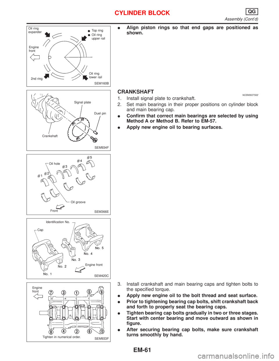
IAlign piston rings so that end gaps are positioned as
shown.
CRANKSHAFTNCEM0027S021. Install signal plate to crankshaft.
2. Set main bearings in their proper positions on cylinder block
and main bearing cap.
IConfirm that correct main bearings are selected by using
Method A or Method B. Refer to EM-57.
IApply new engine oil to bearing surfaces.
3. Install crankshaft and main bearing caps and tighten bolts to
the specified torque.
IApply new engine oil to the bolt thread and seat surface.
IPrior to tightening bearing cap bolts, shift crankshaft back
and forth to properly seat the bearing caps.
ITighten bearing cap bolts gradually in two or three stages.
Start with center bearing and move outward as shown in
figure.
IAfter securing bearing cap bolts, make sure crankshaft
turns smoothly by hand.
SEM160B Oil ring
expanderTop ring
Oil ring
upper rail
Oil ring
lower rail
2nd ring Engine
front
SEM934F CrankshaftSignal plate
Duel pin
SEM366E Oil hole
Oil groove
Front
SEM420C Identification No.
Cap
Engine front
SEM933F Engine
front
Tighten in numerical order.
CYLINDER BLOCKQG
Assembly (Cont'd)
EM-61
Page 1602 of 2267
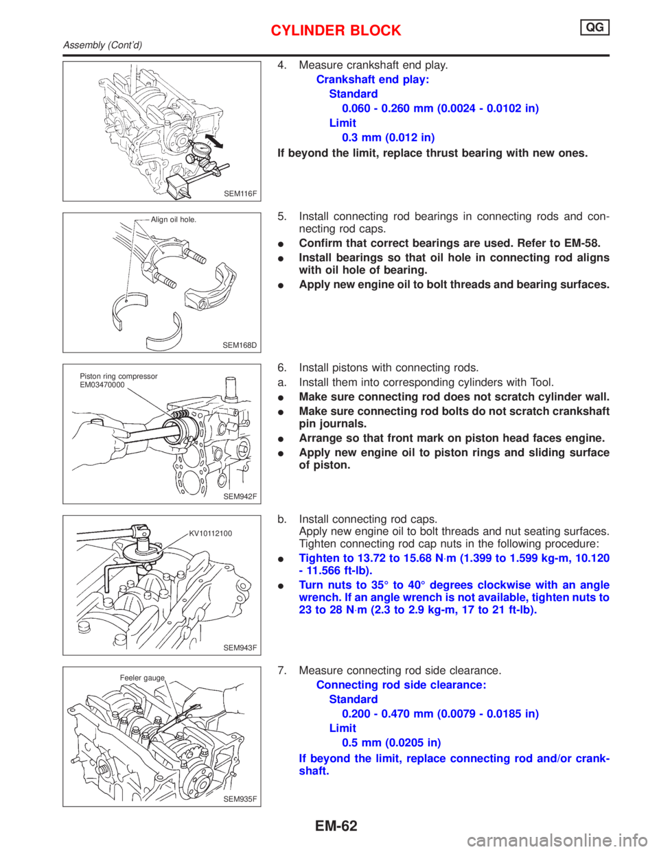
4. Measure crankshaft end play.
Crankshaft end play:
Standard
0.060 - 0.260 mm (0.0024 - 0.0102 in)
Limit
0.3 mm (0.012 in)
If beyond the limit, replace thrust bearing with new ones.
5. Install connecting rod bearings in connecting rods and con-
necting rod caps.
IConfirm that correct bearings are used. Refer to EM-58.
IInstall bearings so that oil hole in connecting rod aligns
with oil hole of bearing.
IApply new engine oil to bolt threads and bearing surfaces.
6. Install pistons with connecting rods.
a. Install them into corresponding cylinders with Tool.
IMake sure connecting rod does not scratch cylinder wall.
IMake sure connecting rod bolts do not scratch crankshaft
pin journals.
IArrange so that front mark on piston head faces engine.
IApply new engine oil to piston rings and sliding surface
of piston.
b. Install connecting rod caps.
Apply new engine oil to bolt threads and nut seating surfaces.
Tighten connecting rod cap nuts in the following procedure:
ITighten to 13.72 to 15.68 N×m (1.399 to 1.599 kg-m, 10.120
- 11.566 ft-lb).
ITurn nuts to 35É to 40É degrees clockwise with an angle
wrench. If an angle wrench is not available, tighten nuts to
23 to 28 N×m (2.3 to 2.9 kg-m, 17 to 21 ft-lb).
7. Measure connecting rod side clearance.
Connecting rod side clearance:
Standard
0.200 - 0.470 mm (0.0079 - 0.0185 in)
Limit
0.5 mm (0.0205 in)
If beyond the limit, replace connecting rod and/or crank-
shaft.
SEM116F
SEM168D Align oil hole.
SEM942F Piston ring compressor
EM03470000
SEM943F KV10112100
SEM935F Feeler gauge
CYLINDER BLOCKQG
Assembly (Cont'd)
EM-62
Page 1603 of 2267
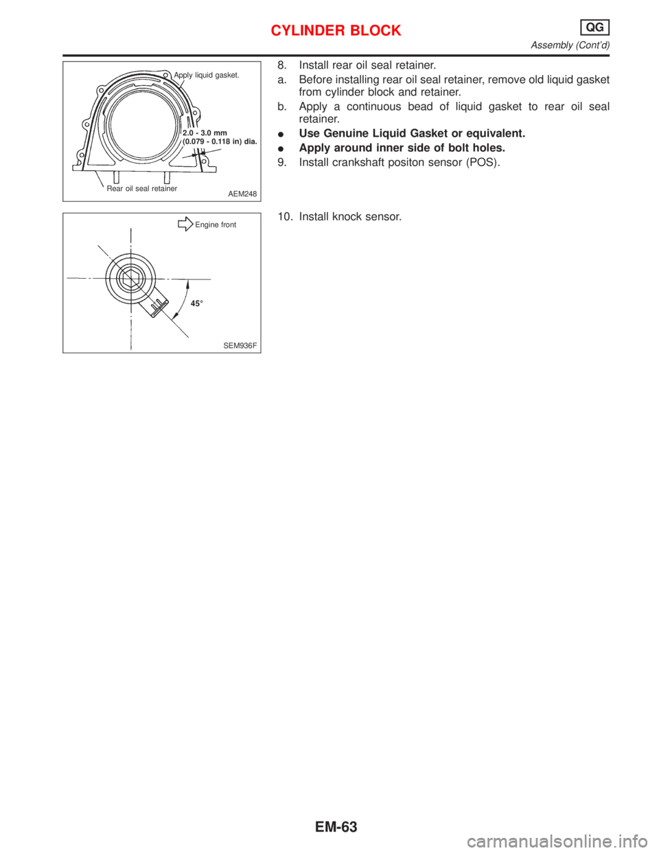
8. Install rear oil seal retainer.
a. Before installing rear oil seal retainer, remove old liquid gasket
from cylinder block and retainer.
b. Apply a continuous bead of liquid gasket to rear oil seal
retainer.
IUse Genuine Liquid Gasket or equivalent.
IApply around inner side of bolt holes.
9. Install crankshaft positon sensor (POS).
10. Install knock sensor.
AEM248 Apply liquid gasket.
.2.0 - 3.0 mm
(0.079 - 0.118 in) dia.
Rear oil seal retainer
SEM936F Engine front
CYLINDER BLOCKQG
Assembly (Cont'd)
EM-63
Page 1604 of 2267
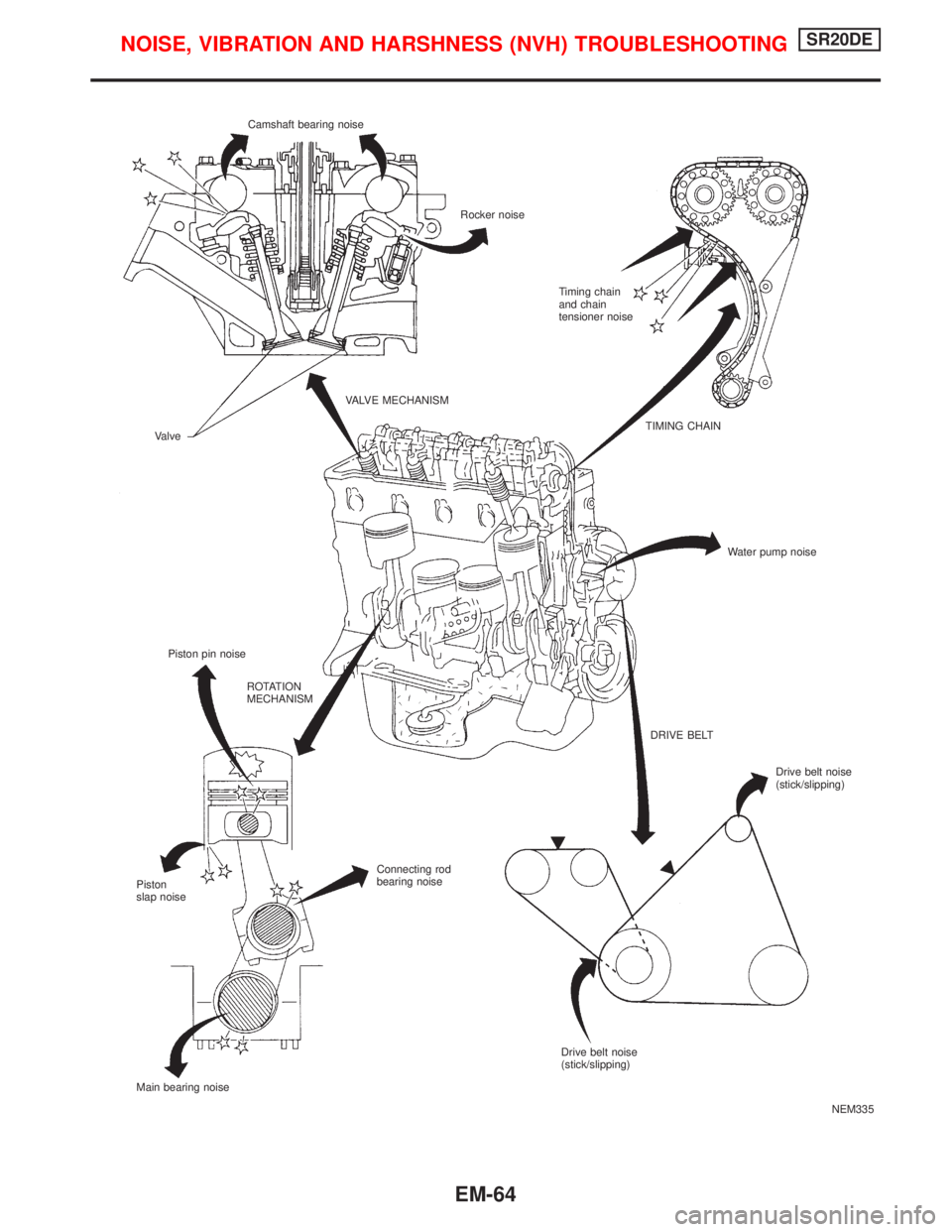
NEM335 Camshaft bearing noise
Rocker noise
Timing chain
and chain
tensioner noise
VALVE MECHANISM
Valve
Piston pin noiseTIMING CHAIN
Water pump noise
ROTATION
MECHANISM
DRIVE BELT
Connecting rod
bearing noise
Piston
slap noise
Main bearing noiseDrive belt noise
(stick/slipping)
Drive belt noise
(stick/slipping)
NOISE, VIBRATION AND HARSHNESS (NVH) TROUBLESHOOTINGSR20DE
EM-64
Page 1605 of 2267
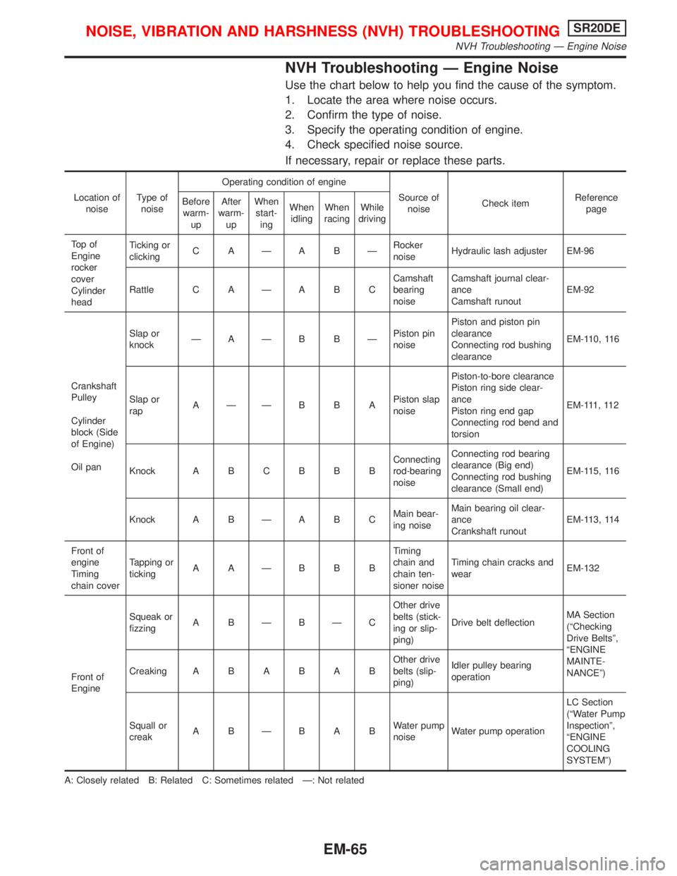
NVH Troubleshooting Ð Engine Noise
Use the chart below to help you find the cause of the symptom.
1. Locate the area where noise occurs.
2. Confirm the type of noise.
3. Specify the operating condition of engine.
4. Check specified noise source.
If necessary, repair or replace these parts.
Location of
noiseType of
noiseOperating condition of engine
Source of
noiseCheck itemReference
page Before
warm-
upAfter
warm-
upWhen
start-
ingWhen
idlingWhen
racingWhile
driving
To p o f
Engine
rocker
cover
Cylinder
headTicking or
clickingC AÐA BÐRocker
noiseHydraulic lash adjuster EM-96
Rattle C A Ð A B CCamshaft
bearing
noiseCamshaft journal clear-
ance
Camshaft runoutEM-92
Crankshaft
Pulley
Cylinder
block (Side
of Engine)
Oil panSlap or
knockÐAÐB BÐPiston pin
noisePiston and piston pin
clearance
Connecting rod bushing
clearanceEM-110, 116
Slap or
rapAÐÐB B APiston slap
noisePiston-to-bore clearance
Piston ring side clear-
ance
Piston ring end gap
Connecting rod bend and
torsionEM-111, 112
Knock A B C B B BConnecting
rod-bearing
noiseConnecting rod bearing
clearance (Big end)
Connecting rod bushing
clearance (Small end)EM-115, 116
Knock A B Ð A B CMain bear-
ing noiseMain bearing oil clear-
ance
Crankshaft runoutEM-113, 114
Front of
engine
Timing
chain coverTapping or
tickingAAÐBBBTiming
chain and
chain ten-
sioner noiseTiming chain cracks and
wearEM-132
Front of
EngineSqueak or
fizzingA BÐBÐCOther drive
belts (stick-
ing or slip-
ping)Drive belt deflectionMA Section
(ªChecking
Drive Beltsº,
ªENGINE
MAINTE-
NANCEº) CreakingABABABOther drive
belts (slip-
ping)Idler pulley bearing
operation
Squall or
creakABÐBABWater pump
noiseWater pump operationLC Section
(ªWater Pump
Inspectionº,
ªENGINE
COOLING
SYSTEMº)
A: Closely related B: Related C: Sometimes related Ð: Not related
NOISE, VIBRATION AND HARSHNESS (NVH) TROUBLESHOOTINGSR20DE
NVH Troubleshooting Ð Engine Noise
EM-65
Page 1606 of 2267
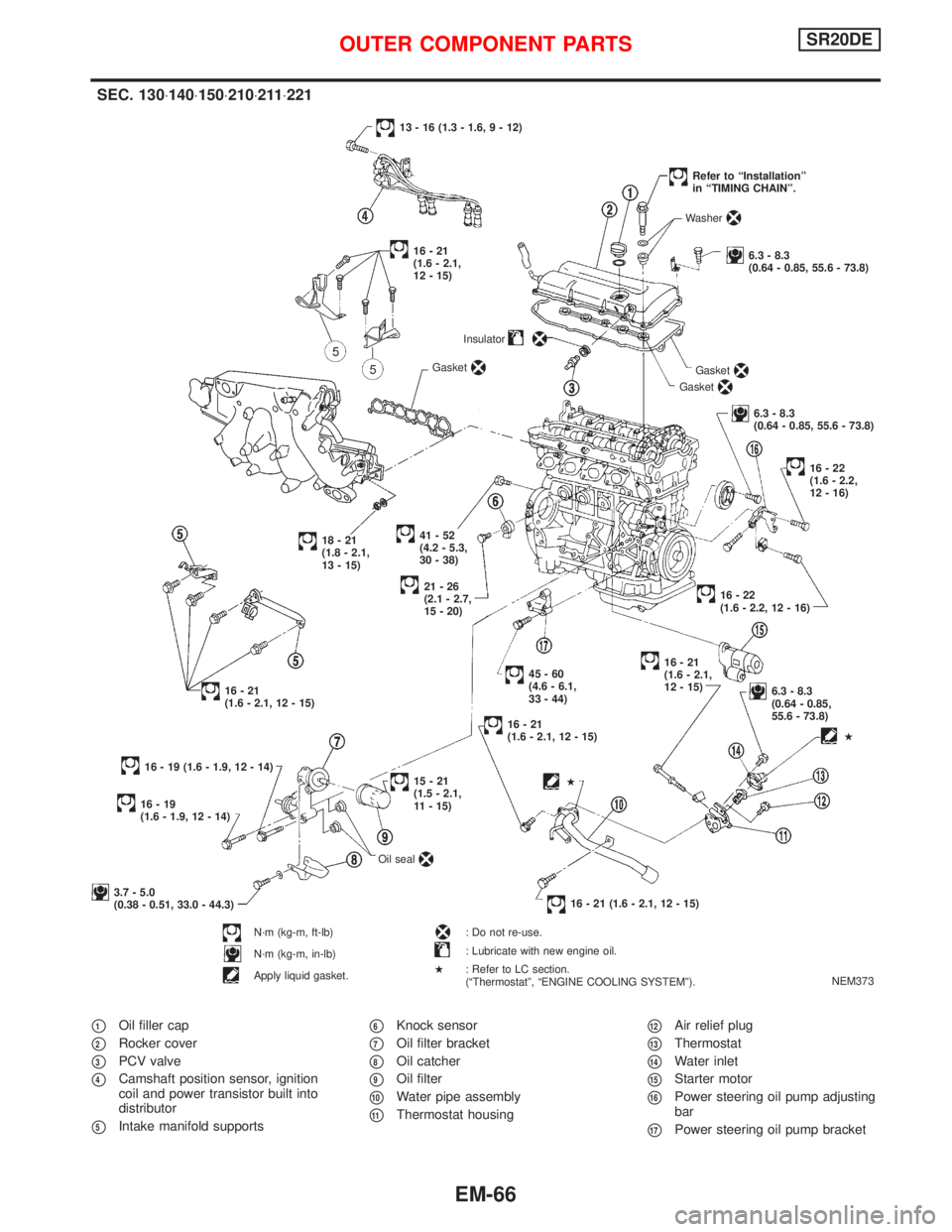
p1Oil filler cap
p2Rocker cover
p3PCV valve
p4Camshaft position sensor, ignition
coil and power transistor built into
distributor
p5Intake manifold supports
p6Knock sensor
p7Oil filter bracket
p8Oil catcher
p9Oil filter
p10Water pipe assembly
p11Thermostat housing
p12Air relief plug
p13Thermostat
p14Water inlet
p15Starter motor
p16Power steering oil pump adjusting
bar
p17Power steering oil pump bracket
NEM373
SEC. 130×140×150×210×211×221
.41-52
(4.2 - 5.3,
30 - 38)Insulator
21-26
(2.1 - 2.7,
15 - 20)
18-21
(1.8 - 2.1,
13 - 15)
16-21
(1.6 - 2.1, 12 - 15)
45-60
(4.6 - 6.1,
33 - 44)
16-21
(1.6 - 2.1, 12 - 15)
16 - 19 (1.6 - 1.9, 12 - 14)Gasket
13 - 16 (1.3 - 1.6, 9 - 12)
Gasket
Gasket
Washer
6.3 - 8.3
(0.64 - 0.85, 55.6 - 73.8)
Refer to ªInstallationº
in ªTIMING CHAINº.
6.3 - 8.3
(0.64 - 0.85, 55.6 - 73.8)
16-22
(1.6 - 2.2,
12 - 16)
.16-22
(1.6 - 2.2, 12 - 16)
16-21
(1.6 - 2.1,
12 - 15)
6.3 - 8.3
(0.64 - 0.85,
55.6 - 73.8)
16 - 21 (1.6 - 2.1, 12 - 15)
16-19
(1.6 - 1.9, 12 - 14)
15-21
(1.5 - 2.1,
11 - 15)
3.7 - 5.0
(0.38 - 0.51, 33.0 - 44.3)
N´m (kg-m, ft-lb)
N´m (kg-m, in-lb)
Apply liquid gasket.Oil seal
: Do not re-use.
: Lubricate with new engine oil.
: Refer to LC section.
(ªThermostatº, ªENGINE COOLING SYSTEMº).
H
H
H
16-21
(1.6 - 2.1,
12 - 15)
OUTER COMPONENT PARTSSR20DE
EM-66
Page 1607 of 2267
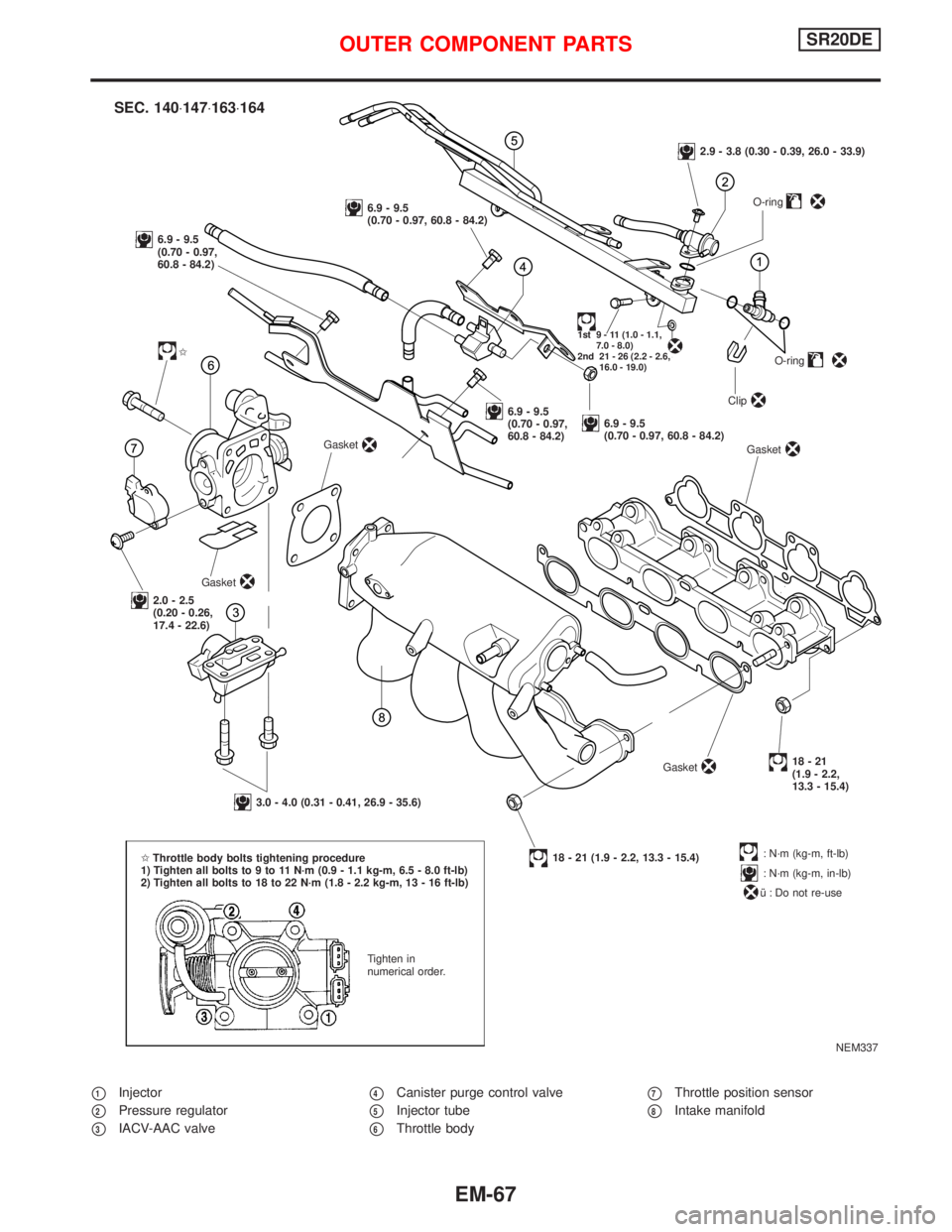
p1Injector
p2Pressure regulator
p3IACV-AAC valve
p4Canister purge control valve
p5Injector tube
p6Throttle body
p7Throttle position sensor
p8Intake manifold
NEM337
.
SEC. 140×147×163×164
6.9 - 9.5
(0.70 - 0.97,
60.8 - 84.2)
6.9 - 9.5
(0.70 - 0.97, 60.8 - 84.2)
2.9 - 3.8 (0.30 - 0.39, 26.0 - 33.9)
O-ring
1st 9 - 11 (1.0 - 1.1,
7.0 - 8.0)
2nd 21 - 26 (2.2 - 2.6,
16.0 - 19.0)
I
Gasket
6.9 - 9.5
(0.70 - 0.97,
60.8 - 84.2)6.9 - 9.5
(0.70 - 0.97, 60.8 - 84.2)O-ring
Clip
Gasket
2.0 - 2.5
(0.20 - 0.26,
17.4 - 22.6)Gasket
3.0 - 4.0 (0.31 - 0.41, 26.9 - 35.6)
18 - 21 (1.9 - 2.2, 13.3 - 15.4)Gasket
18-21
(1.9 - 2.2,
13.3 - 15.4)
: N´m (kg-m, ft-lb)
: N´m (kg-m, in-lb)
î : Do not re-use IThrottle body bolts tightening procedure
1) Tighten all bolts to 9 to 11 N´m (0.9 - 1.1 kg-m, 6.5 - 8.0 ft-lb)
2) Tighten all bolts to 18 to 22 N´m (1.8 - 2.2 kg-m, 13 - 16 ft-lb)
Tighten in
numerical order.
OUTER COMPONENT PARTSSR20DE
EM-67
Page 1608 of 2267
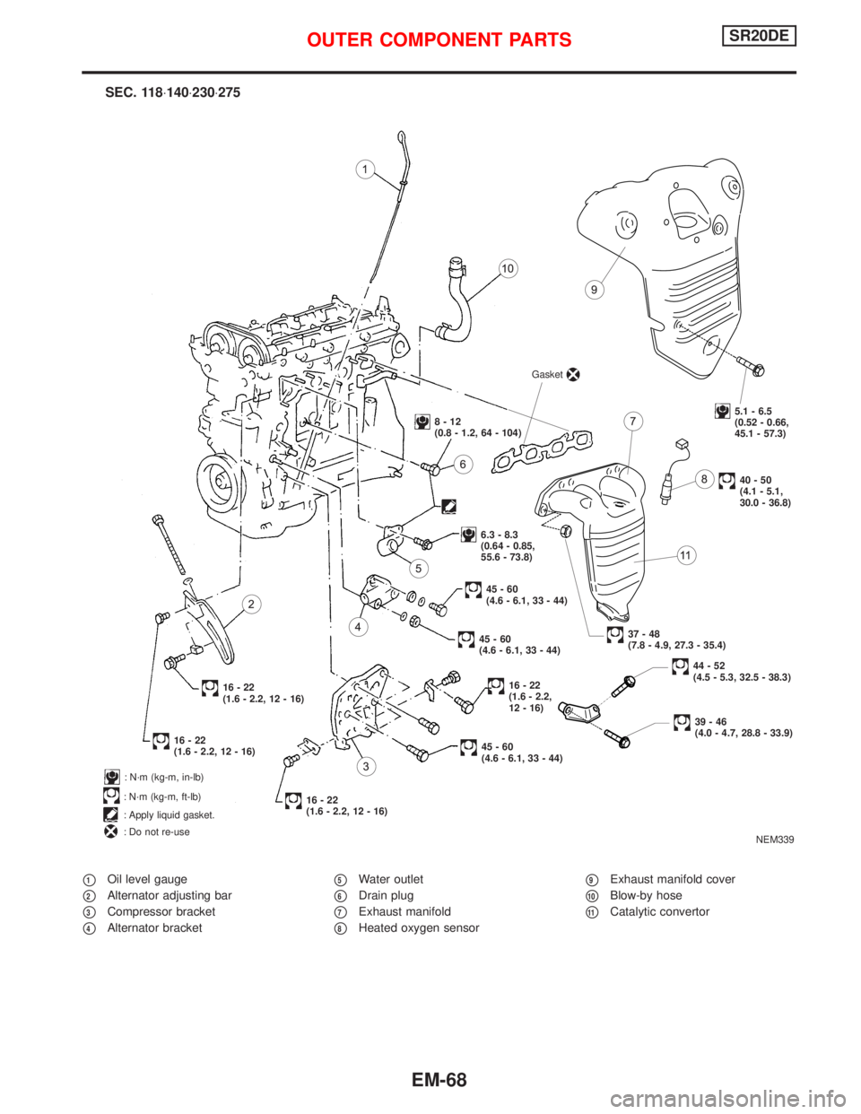
p1Oil level gauge
p2Alternator adjusting bar
p3Compressor bracket
p4Alternator bracket
p5Water outlet
p6Drain plug
p7Exhaust manifold
p8Heated oxygen sensor
p9Exhaust manifold cover
p10Blow-by hose
p11Catalytic convertor
NEM339
: N´m (kg-m, in-lb)
: N´m (kg-m, ft-lb)
: Apply liquid gasket.
: Do not re-use
SEC. 118×140×230×275
Gasket
5.1 - 6.5
(0.52 - 0.66,
45.1 - 57.3)
40-50
(4.1 - 5.1,
30.0 - 36.8)
8-12
(0.8 - 1.2, 64 - 104)
6.3 - 8.3
(0.64 - 0.85,
55.6 - 73.8)
37-48
(7.8 - 4.9, 27.3 - 35.4)
45-60
(4.6 - 6.1, 33 - 44)
45-60
(4.6 - 6.1, 33 - 44)
16-22
(1.6 - 2.2, 12 - 16)
16-22
(1.6 - 2.2, 12 - 16)
16-22
(1.6 - 2.2,
12 - 16)
45-60
(4.6 - 6.1, 33 - 44)
16-22
(1.6 - 2.2, 12 - 16)
44-52
(4.5 - 5.3, 32.5 - 38.3)
39-46
(4.0 - 4.7, 28.8 - 33.9)
OUTER COMPONENT PARTSSR20DE
EM-68
Page 1609 of 2267
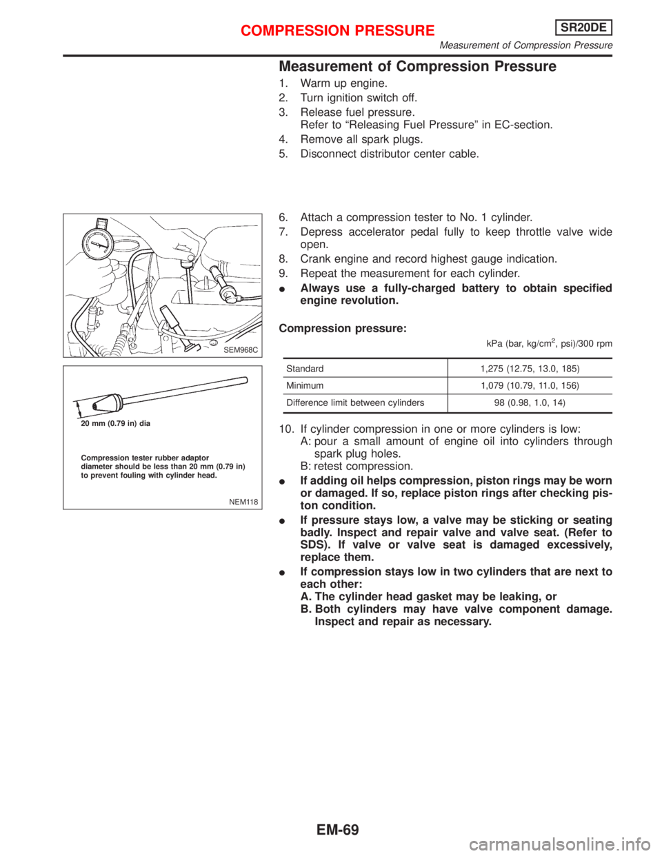
Measurement of Compression Pressure
1. Warm up engine.
2. Turn ignition switch off.
3. Release fuel pressure.
Refer to ªReleasing Fuel Pressureº in EC-section.
4. Remove all spark plugs.
5. Disconnect distributor center cable.
6. Attach a compression tester to No. 1 cylinder.
7. Depress accelerator pedal fully to keep throttle valve wide
open.
8. Crank engine and record highest gauge indication.
9. Repeat the measurement for each cylinder.
IAlways use a fully-charged battery to obtain specified
engine revolution.
Compression pressure:
kPa (bar, kg/cm2, psi)/300 rpm
Standard 1,275 (12.75, 13.0, 185)
Minimum 1,079 (10.79, 11.0, 156)
Difference limit between cylinders 98 (0.98, 1.0, 14)
10. If cylinder compression in one or more cylinders is low:
A: pour a small amount of engine oil into cylinders through
spark plug holes.
B: retest compression.
IIf adding oil helps compression, piston rings may be worn
or damaged. If so, replace piston rings after checking pis-
ton condition.
IIf pressure stays low, a valve may be sticking or seating
badly. Inspect and repair valve and valve seat. (Refer to
SDS). If valve or valve seat is damaged excessively,
replace them.
IIf compression stays low in two cylinders that are next to
each other:
A. The cylinder head gasket may be leaking, or
B. Both cylinders may have valve component damage.
Inspect and repair as necessary.
SEM968C
NEM118 20 mm (0.79 in) dia
Compression tester rubber adaptor
diameter should be less than 20 mm (0.79 in)
to prevent fouling with cylinder head.
COMPRESSION PRESSURESR20DE
Measurement of Compression Pressure
EM-69
Page 1610 of 2267
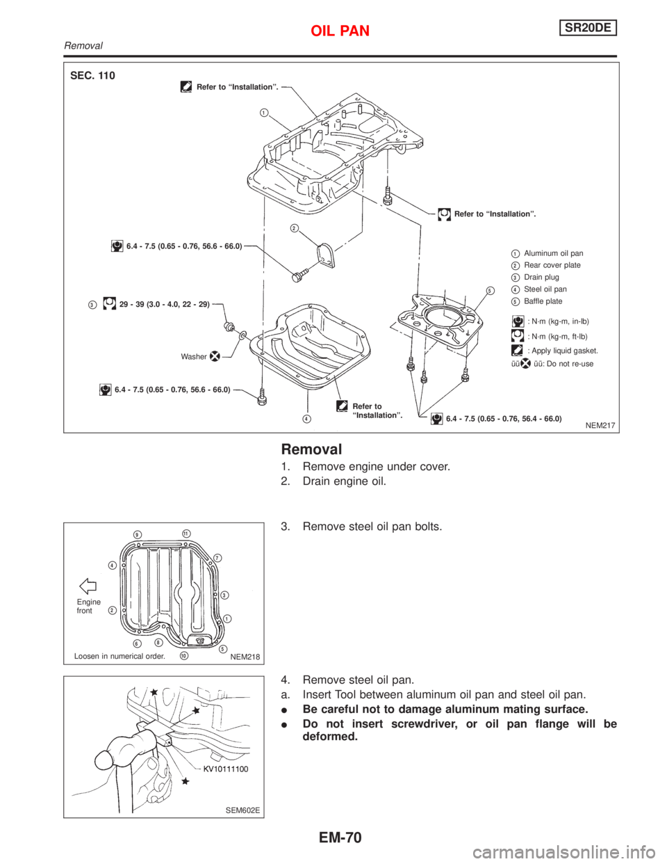
Removal
1. Remove engine under cover.
2. Drain engine oil.
3. Remove steel oil pan bolts.
4. Remove steel oil pan.
a. Insert Tool between aluminum oil pan and steel oil pan.
IBe careful not to damage aluminum mating surface.
IDo not insert screwdriver, or oil pan flange will be
deformed.
NEM217
SEC. 110Refer to ªInstallationº.
Refer to ªInstallationº.
6.4 - 7.5 (0.65 - 0.76, 56.6 - 66.0)
p329 - 39 (3.0 - 4.0, 22 - 29)
6.4 - 7.5 (0.65 - 0.76, 56.6 - 66.0)
Refer to
ªInstallationº.
6.4 - 7.5 (0.65 - 0.76, 56.4 - 66.0)
p1Aluminum oil pan
p2Rear cover plate
p3Drain plug
p4Steel oil pan
p5Baffle plate
: N´m (kg-m, in-lb)
: N´m (kg-m, ft-lb)
: Apply liquid gasket.
îî
îî: Do not re-use
p1
p2
Washer
p4
p5
NEM218 Engine
front
p9p11
p7
p3
p1
p5p10
p8p6
p2
p4
Loosen in numerical order.
SEM602E
OIL PANSR20DE
Removal
EM-70