NISSAN PRIMERA 1999 Electronic Repair Manual
Manufacturer: NISSAN, Model Year: 1999, Model line: PRIMERA, Model: NISSAN PRIMERA 1999Pages: 2267, PDF Size: 35.74 MB
Page 1691 of 2267
Assembly
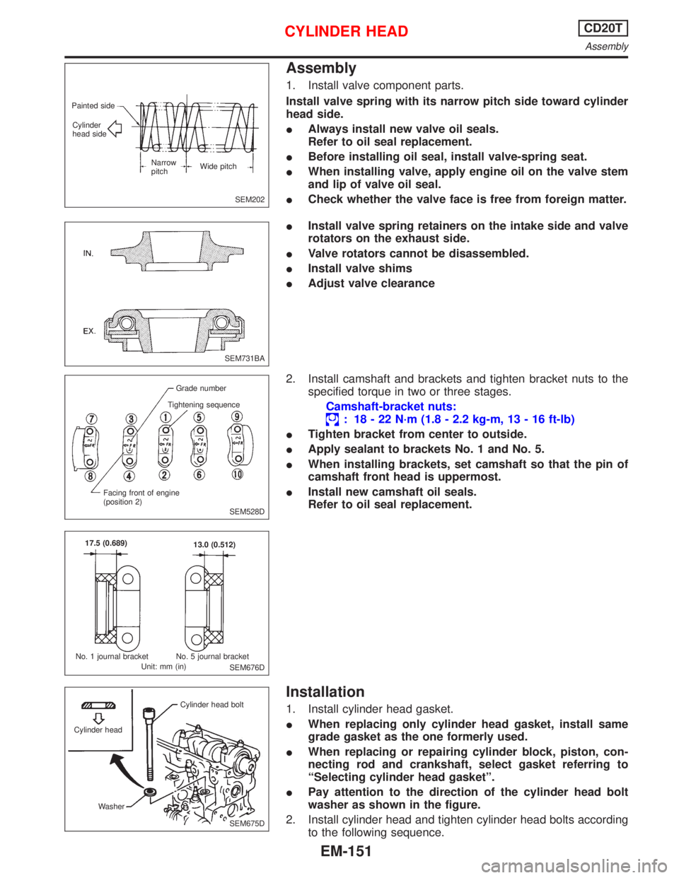
1. Install valve component parts.
Install valve spring with its narrow pitch side toward cylinder
head side.
IAlways install new valve oil seals.
Refer to oil seal replacement.
IBefore installing oil seal, install valve-spring seat.
IWhen installing valve, apply engine oil on the valve stem
and lip of valve oil seal.
ICheck whether the valve face is free from foreign matter.
IInstall valve spring retainers on the intake side and valve
rotators on the exhaust side.
IValve rotators cannot be disassembled.
IInstall valve shims
IAdjust valve clearance
2. Install camshaft and brackets and tighten bracket nuts to the
specified torque in two or three stages.
Camshaft-bracket nuts:
: 18 - 22 N´m (1.8 - 2.2 kg-m, 13 - 16 ft-lb)
ITighten bracket from center to outside.
IApply sealant to brackets No. 1 and No. 5.
IWhen installing brackets, set camshaft so that the pin of
camshaft front head is uppermost.
IInstall new camshaft oil seals.
Refer to oil seal replacement.
Installation
1. Install cylinder head gasket.
IWhen replacing only cylinder head gasket, install same
grade gasket as the one formerly used.
IWhen replacing or repairing cylinder block, piston, con-
necting rod and crankshaft, select gasket referring to
ªSelecting cylinder head gasketº.
IPay attention to the direction of the cylinder head bolt
washer as shown in the figure.
2. Install cylinder head and tighten cylinder head bolts according
to the following sequence.
SEM202 Painted side
Cylinder
head side
Narrow
pitchWide pitch
SEM731BA
SEM528D Grade number
Tightening sequence
Facing front of engine
(position 2)
SEM676D 17.5 (0.689)
13.0 (0.512)
No. 1 journal bracket No. 5 journal bracket
Unit: mm (in)
SEM675D Cylinder headCylinder head bolt
Washer
CYLINDER HEADCD20T
Assembly
EM-151
Page 1692 of 2267
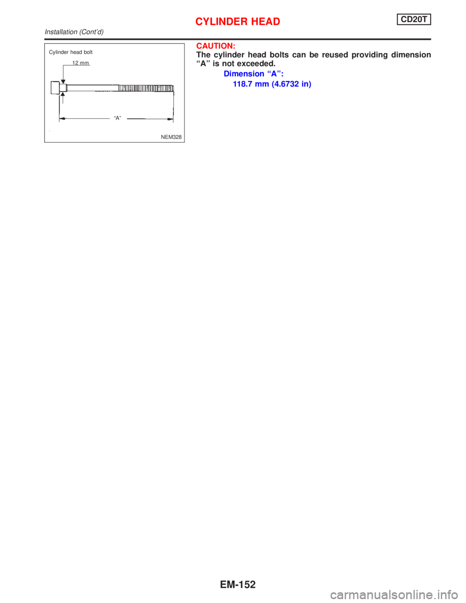
CAUTION:
The cylinder head bolts can be reused providing dimension
ªAº is not exceeded.
Dimension ªAº:
118.7 mm (4.6732 in)
NEM328 Cylinder head bolt
12 mm
ªAº
CYLINDER HEADCD20T
Installation (Cont'd)
EM-152
Page 1693 of 2267
Tightening procedure
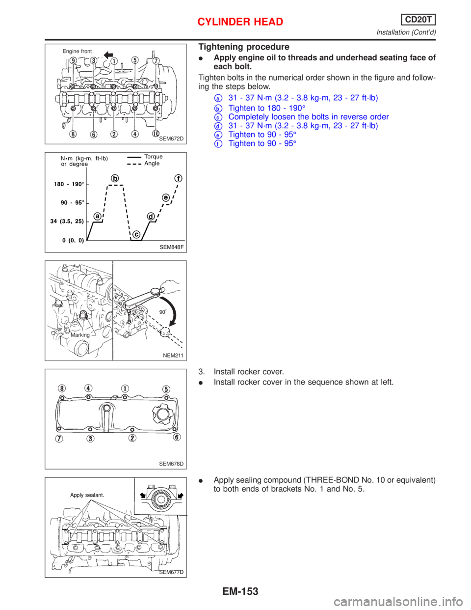
IApply engine oil to threads and underhead seating face of
each bolt.
Tighten bolts in the numerical order shown in the figure and follow-
ing the steps below.
pa31 - 37 N´m (3.2 - 3.8 kg-m, 23 - 27 ft-lb)
pbTighten to 180 - 190É
pcCompletely loosen the bolts in reverse order
pd31 - 37 N´m (3.2 - 3.8 kg-m, 23 - 27 ft-lb)
peTighten to 90 - 95É
pfTighten to 90 - 95É
3. Install rocker cover.
IInstall rocker cover in the sequence shown at left.
IApply sealing compound (THREE-BOND No. 10 or equivalent)
to both ends of brackets No. 1 and No. 5.SEM672D Engine front
SEM848F
NEM211 Marking
SEM678D
SEM677D Apply sealant.
CYLINDER HEADCD20T
Installation (Cont'd)
EM-153
Page 1694 of 2267
Selecting cylinder head gasket
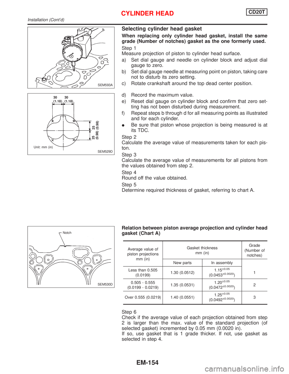
When replacing only cylinder head gasket, install the same
grade (Number of notches) gasket as the one formerly used.
Step 1
Measure projection of piston to cylinder head surface.
a) Set dial gauge and needle on cylinder block and adjust dial
gauge to zero.
b) Set dial gauge needle at measuring point on piston, taking care
not to disturb its zero setting.
c) Rotate crankshaft around the top dead center position.
d) Record the maximum value.
e) Reset dial gauge on cylinder block and confirm that zero set-
ting has not been disturbed during measurement.
f) Repeat steps b through d for all measuring points as illustrated
and for each cylinder.
IBe sure that piston whose projection is being measured is at
its TDC.
Step 2
Calculate the average value of measurements taken for each pis-
ton.
Step 3
Calculate the average value of measurements for all pistons from
the values obtained from step 2.
Step 4
Round off the value obtained.
Step 5
Determine required thickness of gasket, referring to chart A.
Relation between piston average projection and cylinder head
gasket (Chart A)
Average value of
piston projections
mm (in)Gasket thickness
mm (in)Grade
(Number of
notches)
New parts In assembly
Less than 0.505
(0.0199)1.30 (0.0512)1.15
0.05
(0.0453 0.0020)1
0.505 - 0.555
(0.0199 - 0.0219)1.35 (0.0531)1.20
0.05
(0.0472 0.0020)2
Over 0.555 (0.0219) 1.40 (0.0551)1.25
0.05
(0.0492 0.0020)3
Step 6
Check if the average value of each projection obtained from step
2 is larger than the max. value of the standard projection (of
selected gasket) incremented by 0.05 mm (0.0020 in).
If so, use gasket that is 1 grade thicker. If not, use gasket as
selected in step 4.
SEM593A
SEM529D 30
(1.18)30
(1.18)
Unit: mm (in)
25
(0.98)25
(0.98)
SEM530D Notch
CYLINDER HEADCD20T
Installation (Cont'd)
EM-154
Page 1695 of 2267
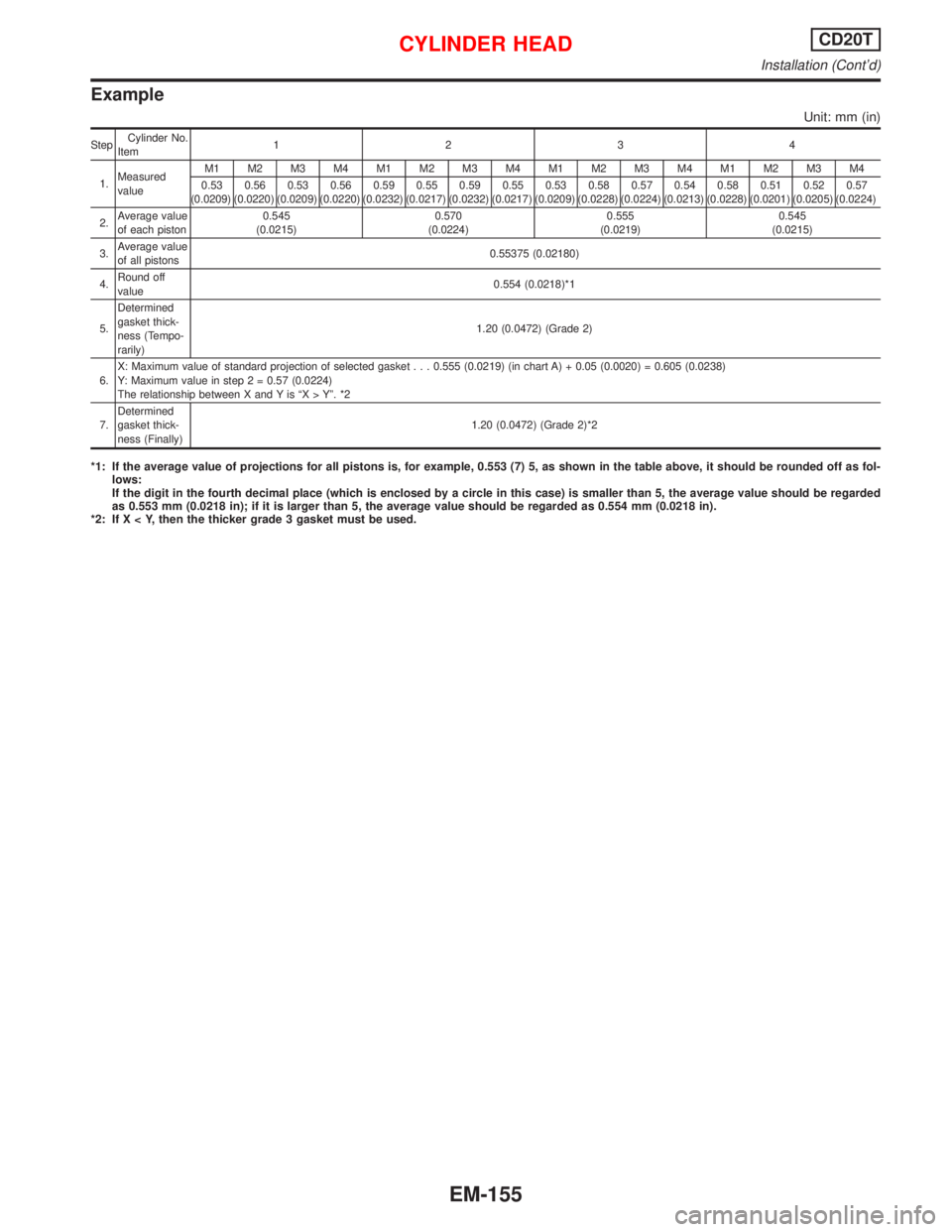
Example
Unit: mm (in)
StepCylinder No.
Item1234
1.Measured
valueM1 M2 M3 M4 M1 M2 M3 M4 M1 M2 M3 M4 M1 M2 M3 M4
0.53
(0.0209)0.56
(0.0220)0.53
(0.0209)0.56
(0.0220)0.59
(0.0232)0.55
(0.0217)0.59
(0.0232)0.55
(0.0217)0.53
(0.0209)0.58
(0.0228)0.57
(0.0224)0.54
(0.0213)0.58
(0.0228)0.51
(0.0201)0.52
(0.0205)0.57
(0.0224)
2.Average value
of each piston0.545
(0.0215)0.570
(0.0224)0.555
(0.0219)0.545
(0.0215)
3.Average value
of all pistons0.55375 (0.02180)
4.Round off
value0.554 (0.0218)*1
5.Determined
gasket thick-
ness (Tempo-
rarily)1.20 (0.0472) (Grade 2)
6.X: Maximum value of standard projection of selected gasket...0.555 (0.0219) (in chart A) + 0.05 (0.0020) = 0.605 (0.0238)
Y: Maximum value in step 2 = 0.57 (0.0224)
The relationship between X and Y is ªX > Yº. *2
7.Determined
gasket thick-
ness (Finally)1.20 (0.0472) (Grade 2)*2
*1: If the average value of projections for all pistons is, for example, 0.553 (7) 5, as shown in the table above, it should be rounded off as fol-
lows:
If the digit in the fourth decimal place (which is enclosed by a circle in this case) is smaller than 5, the average value should be regarded
as 0.553 mm (0.0218 in); if it is larger than 5, the average value should be regarded as 0.554 mm (0.0218 in).
*2: If X < Y, then the thicker grade 3 gasket must be used.
CYLINDER HEADCD20T
Installation (Cont'd)
EM-155
Page 1696 of 2267
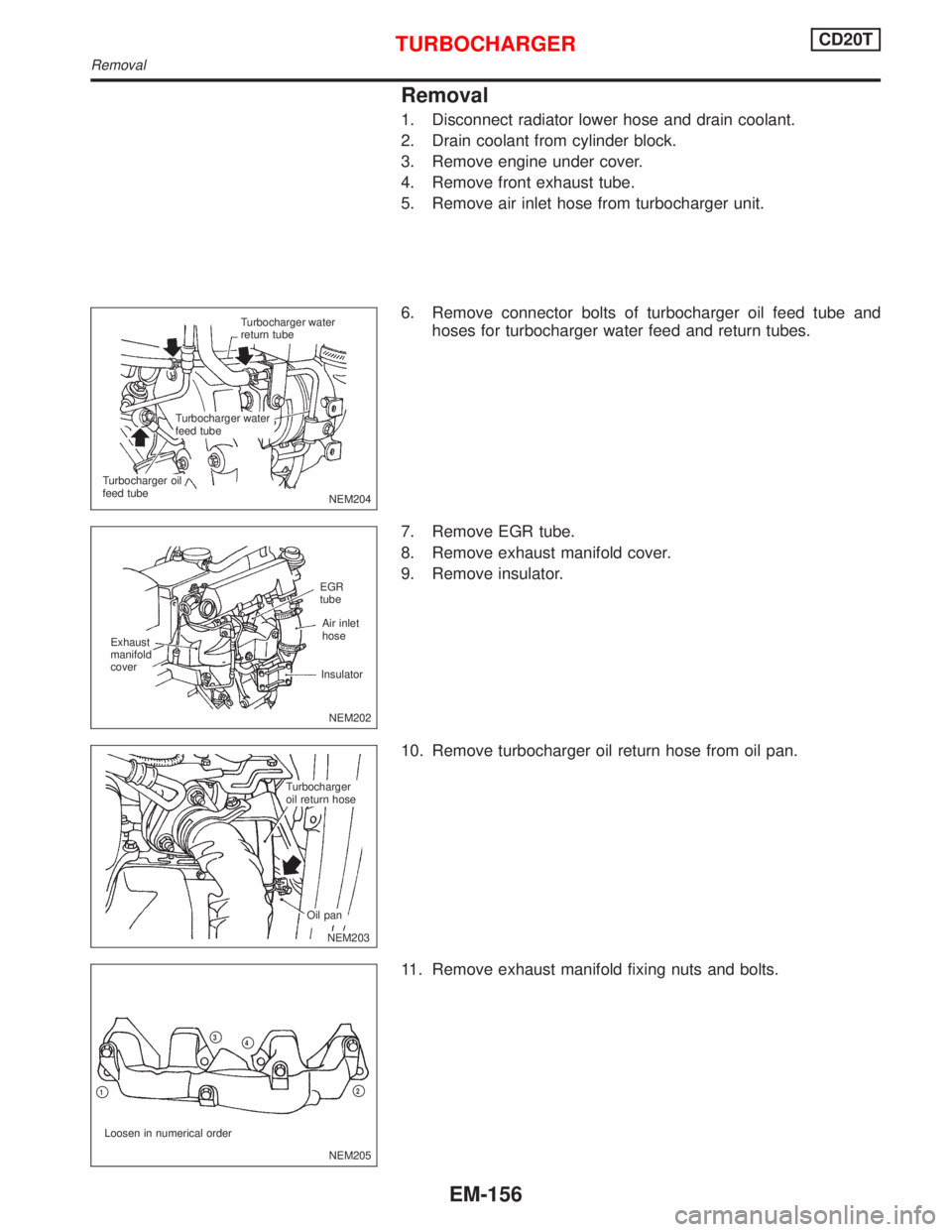
Removal
1. Disconnect radiator lower hose and drain coolant.
2. Drain coolant from cylinder block.
3. Remove engine under cover.
4. Remove front exhaust tube.
5. Remove air inlet hose from turbocharger unit.
6. Remove connector bolts of turbocharger oil feed tube and
hoses for turbocharger water feed and return tubes.
7. Remove EGR tube.
8. Remove exhaust manifold cover.
9. Remove insulator.
10. Remove turbocharger oil return hose from oil pan.
11. Remove exhaust manifold fixing nuts and bolts.
NEM204
.Turbocharger water
return tube
.Turbocharger water
feed tube
.Turbocharger oil
feed tube
NEM202 Exhaust
manifold
coverAir inlet
hose EGR
tube
Insulator
.NEM203
.Turbocharger
oil return hose
.Oil pan
NEM205 Loosen in numerical order
p1p2
p3p4
TURBOCHARGERCD20T
Removal
EM-156
Page 1697 of 2267
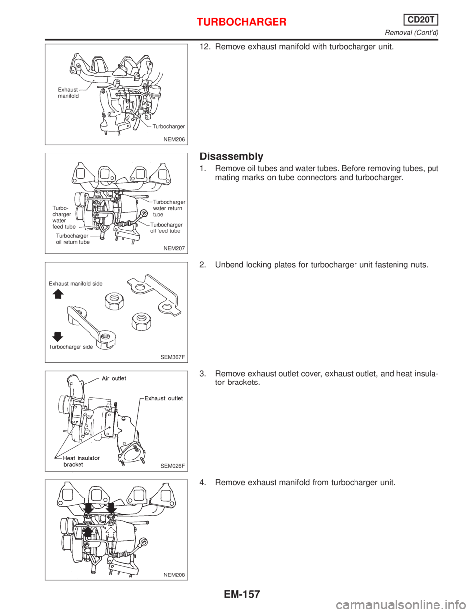
12. Remove exhaust manifold with turbocharger unit.
Disassembly
1. Remove oil tubes and water tubes. Before removing tubes, put
mating marks on tube connectors and turbocharger.
2. Unbend locking plates for turbocharger unit fastening nuts.
3. Remove exhaust outlet cover, exhaust outlet, and heat insula-
tor brackets.
4. Remove exhaust manifold from turbocharger unit.
NEM206 Exhaust
manifold
Turbocharger
NEM207 Turbocharger
water return
tube
Turbocharger
oil feed tube Turbo-
charger
water
feed tube
Turbocharger
oil return tube
SEM367F Exhaust manifold side
Turbocharger side
SEM026F
NEM208
TURBOCHARGERCD20T
Removal (Cont'd)
EM-157
Page 1698 of 2267
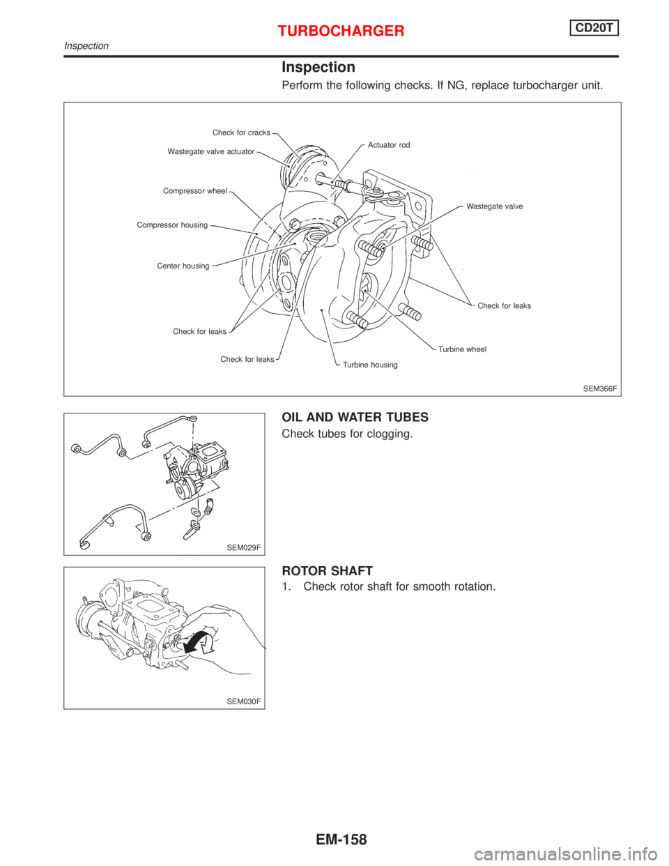
Inspection
Perform the following checks. If NG, replace turbocharger unit.
OIL AND WATER TUBES
Check tubes for clogging.
ROTOR SHAFT
1. Check rotor shaft for smooth rotation.
SEM366F Check for cracks
Wastegate valve actuator
Compressor wheel
Compressor housing
Center housing
Check for leaks
Check for leaks
Turbine housingTurbine wheelCheck for leaks Wastegate valve Actuator rod
SEM029F
SEM030F
TURBOCHARGERCD20T
Inspection
EM-158
Page 1699 of 2267
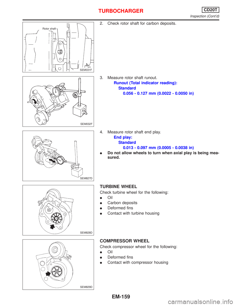
2. Check rotor shaft for carbon deposits.
3. Measure rotor shaft runout.
Runout (Total indicator reading):
Standard
0.056 - 0.127 mm (0.0022 - 0.0050 in)
4. Measure rotor shaft end play.
End play:
Standard
0.013 - 0.097 mm (0.0005 - 0.0038 in)
IDo not allow wheels to turn when axial play is being mea-
sured.
TURBINE WHEEL
Check turbine wheel for the following:
IOil
ICarbon deposits
IDeformed fins
IContact with turbine housing
COMPRESSOR WHEEL
Check compressor wheel for the following:
IOil
IDeformed fins
IContact with compressor housing
.SEM031F Rotor shaft
SEM032F
SEM827D
SEM828D
SEM829D
TURBOCHARGERCD20T
Inspection (Cont'd)
EM-159
Page 1700 of 2267
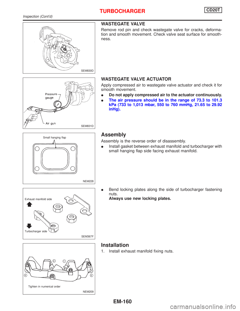
WASTEGATE VALVE
Remove rod pin and check wastegate valve for cracks, deforma-
tion and smooth movement. Check valve seat surface for smooth-
ness.
WASTEGATE VALVE ACTUATOR
Apply compressed air to wastegate valve actuator and check it for
smooth movement.
IDo not apply compressed air to the actuator continuously.
IThe air pressure should be in the range of 73.3 to 101.3
kPa (733 to 1,013 mbar, 550 to 760 mmHg, 21.65 to 29.92
inHg).
Assembly
Assembly is the reverse order of disassembly.
IInstall gasket between exhaust manifold and turbocharger with
small hanging flap side facing exhaust manifold.
IBend locking plates along the side of turbocharger fastening
nuts.
Always use new locking plates.
Installation
1. Install exhaust manifold fixing nuts.
SEM830D
SEM831D
NEM228 Small hanging flap
SEM367F Exhaust manifold side
Turbocharger side
NEM209 Tighten in numerical order
p4
p2p1
p3
TURBOCHARGERCD20T
Inspection (Cont'd)
EM-160