NISSAN PRIMERA 1999 Electronic Repair Manual
Manufacturer: NISSAN, Model Year: 1999, Model line: PRIMERA, Model: NISSAN PRIMERA 1999Pages: 2267, PDF Size: 35.74 MB
Page 1661 of 2267
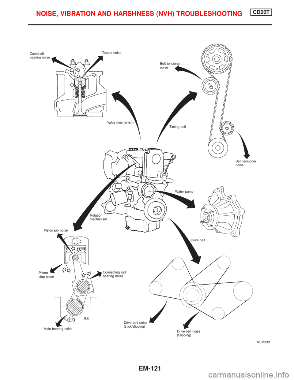
NEM333 Camshaft
bearing noiseTappet noise
Belt tensioner
noise
Valve mechanism
Piston pin noiseTiming belt
Water pump
Rotation
mechanism
Drive belt
Connecting rod
bearing noise Piston
slap noise
Main bearing noiseDrive belt noise
(stick/slipping)
Belt tensioner
noise
Drive belt noise
(Slipping)
NOISE, VIBRATION AND HARSHNESS (NVH) TROUBLESHOOTINGCD20T
EM-121
Page 1662 of 2267
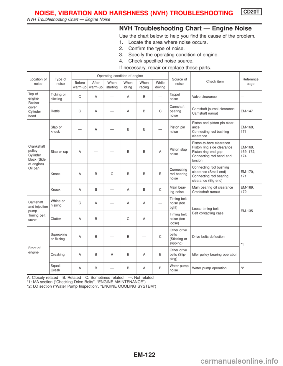
NVH Troubleshooting Chart Ð Engine Noise
Use the chart below to help you find the cause of the problem.
1. Locate the area where noise occurs.
2. Confirm the type of noise.
3. Specify the operating condition of engine.
4. Check specified noise source.
If necessary, repair or replace these parts.
Location of
noiseType of
noiseOperating condition of engine
Source of
noiseCheck itemReference
page Before
warm-upAfter
warm-upWhen
startingWhen
idlingWhen
racingWhile
driving
To p o f
engine
Rocker
cover
Cylinder
headTicking or
clickingCAÐABÐTappet
noiseValve clearance Ð
Rattle C A Ð A B CCamshaft
bearing
noiseCamshaft journal clearance
Camshaft runoutEM-147
Crankshaft
pulley
Cylinder
block (Side
of engine)
Oil panSlap or
knockÐAÐB BÐPiston pin
noisePiston and piston pin clear-
ance
Connecting rod bushing
clearanceEM-168,
171
Slap or rap A Ð Ð B B APiston slap
noisePiston-to-bore clearance
Piston ring side clearance
Piston ring end gap
Connecting rod bend and
torsionEM-168,
169, 172,
174
Knock A B C B B BConnecting
rod bearing
noiseConnecting rod bushing
clearance (Small end)
Connecting rod bearing
clearance (Big end)EM-170,
171
Knock A B Ð A B CMain bear-
ing noiseMain bearing oil clearance
Crankshaft runoutEM-169,
172
Camshaft
and injection
pump
Timing belt
coverWhine or
hissingCAÐAAÐTiming belt
noise (too
tight)
Loose timing belt
Belt contacting caseEM-135
Clatter A B Ð C A ÐTiming belt
noise (too
loose)
Front of
engineSqueaking
or fizzingABÐBÐCOther drive
belts
(Sticking or
slipping)Drive belts deflection
*1
CreakingABABABOther drive
belts (Slip-
ping)Idler pulley bearing operation
Squall
CreakABÐBABWater pump
noiseWater pump operation *2
A: Closely related B: Related C: Sometimes related Ð: Not related
*1: MA section (ªChecking Drive Beltsº, ªENGINE MAINTENANCEº)
*2: LC section (ªWater Pump Inspectionº, ªENGINE COOLING SYSTEMº)
NOISE, VIBRATION AND HARSHNESS (NVH) TROUBLESHOOTINGCD20T
NVH Troubleshooting Chart Ð Engine Noise
EM-122
Page 1663 of 2267
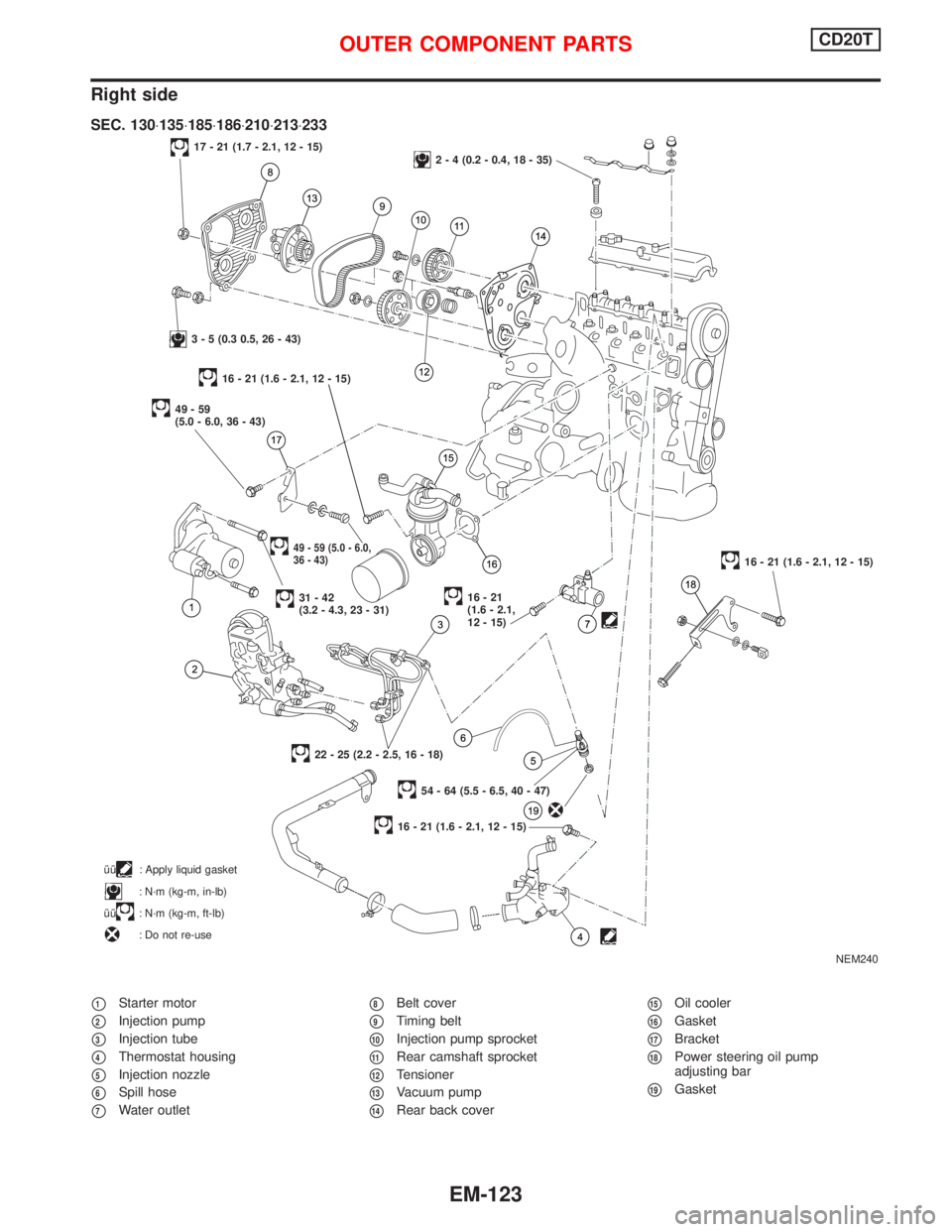
Right side
p1Starter motor
p2Injection pump
p3Injection tube
p4Thermostat housing
p5Injection nozzle
p6Spill hose
p7Water outlet
p8Belt cover
p9Timing belt
p10Injection pump sprocket
p11Rear camshaft sprocket
p12Tensioner
p13Vacuum pump
p14Rear back cover
p15Oil cooler
p16Gasket
p17Bracket
p18Power steering oil pump
adjusting bar
p19Gasket
NEM240
17 - 21 (1.7 - 2.1, 12 - 15)2 - 4 (0.2 - 0.4, 18 - 35)
3 - 5 (0.3 0.5, 26 - 43)
49-59
(5.0 - 6.0, 36 - 43)
49 - 59 (5.0 - 6.0,
36 - 43)
31-42
(3.2 - 4.3, 23 - 31)16-21
(1.6 - 2.1,
12 - 15)
16 - 21 (1.6 - 2.1, 12 - 15)
54 - 64 (5.5 - 6.5, 40 - 47)
22 - 25 (2.2 - 2.5, 16 - 18)
16 - 21 (1.6 - 2.1, 12 - 15)
SEC. 130×135×185×186×210×213×233
îî: Apply liquid gasket
: N´m (kg-m, in-lb)
îî
: N´m (kg-m, ft-lb)
: Do not re-use
16 - 21 (1.6 - 2.1, 12 - 15)
OUTER COMPONENT PARTSCD20T
EM-123
Page 1664 of 2267
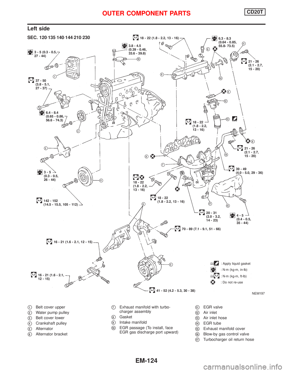
Left side
p1Belt cover upper
p2Water pump pulley
p3Belt cover lower
p4Crankshaft pulley
p5Alternator
p6Alternator bracket
p7Exhaust manifold with turbo-
charger assembly
p8Gasket
p9Intake manifold
p10EGR passage (To install, face
EGR gas discharge port upward)
p11EGR valve
p12Air inlet
p13Air inlet hose
p14EGR tube
p15Exhaust manifold cover
p16Blow-by gas control valve
p17Turbocharger oil return hose
3 - 5 (0.3 - 0.5,
27 - 44)
37-50
(3.8 - 5.1,
27 - 37)p1
6.4 - 8.4
(0.65 - 0.86,
56.6 - 74.3)
p2
p9
p3
3-5
(0.3 - 0.5,
26 - 44)
p4
142 - 152
(14.5 - 15.5, 105 - 112)p6
16 - 21 (1.6 - 2.1, 12 - 15)
16 - 21 (1.6 - 2.1,
12 - 15)îî
: Apply liquid gasket
: N´m (kg-m, in-lb)
îî
: N´m (kg-m, ft-lb)
: Do not re-use
18 - 22 (1.8 - 2.2, 13 - 16)6.3 - 8.3
(0.64 - 0.85,
55.8- 73.5)
p11
p8
p10
.21-26
(2.1 - 2.7,
15 - 20)
p8
p12
p1318-22
(1.8 - 2.2,
13 - 16)
p8
21-26
(2.1 - 2.7,
15 - 20)
p14
39-49
(4.0 - 5.0, 29 - 36)
p8
p7
18-22
(1.8 - 2.2,
13 - 16)
.18-22
(1.8 - 2.2, 13 - 16)
p17p15
4-5
(0.4 - 0.5,
35 - 44)
70 - 89 (7.1 - 9.1, 51 - 66)
p5
41 - 52 (4.2 - 5.3, 30 - 38)
NEM197
SEC. 120×135×140×144×210×230
3.8 - 4.5
(0.39 - 0.46,
33.6 - 39.8)
p16
20-31
(2.0 - 3.2,
14 - 23)
OUTER COMPONENT PARTSCD20T
EM-124
Page 1665 of 2267
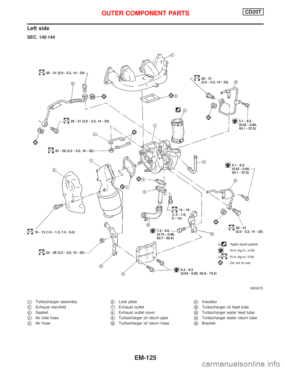
Left side
p1Turbocharger assembly
p2Exhaust manifold
p3Gasket
p4Air inlet hose
p5Air hose
p6Lock plate
p7Exhaust outlet
p8Exhaust outlet cover
p9Turbocharger oil return pipe
p10Turbocharger oil return hose
p11Insulator
p12Turbocharger oil feed tube
p13Turbocharger water feed tube
p14Turbocharger water return tube
p15Bracket
NEM375
p2
20 - 31 (2.0 - 3.2, 14 - 23)
p12
20 - 31 (2.0 - 3.2, 14 - 23)
p6
22 - 29 (2.2 - 3.0, 16 - 22)
p4
p3
p7
p8
p3
p3
p9
10 - 13 (1.0 - 1.3, 7.2 - 9.4)
22 - 29 (2.2 - 3.0, 16 - 22)
p15
p11
7.2 - 9.6
(0.73 - 0.98,
63.7 - 85.0)
.p10
p15
6.3 - 8.3
(0.64 - 0.85, 55.8 - 73.5)
20-31
(2.0 - 3.2, 14 - 23)
13-19
(1.3 - 1.9,
9 - 14)
p14
5.1 - 6.5
(0.52 - 0.66,
45.1 - 57.5)p5
p1
20-31
(2.0 - 3.2, 14 - 23)p13
5.1 - 6.5
(0.52 - 0.66,
45.1 - 57.5)
SEC. 140×144
îî: Apply liquid gasket
: N´m (kg-m, in-lb)
îî
: N´m (kg-m, ft-lb)
: Do not re-use
OUTER COMPONENT PARTSCD20T
EM-125
Page 1666 of 2267
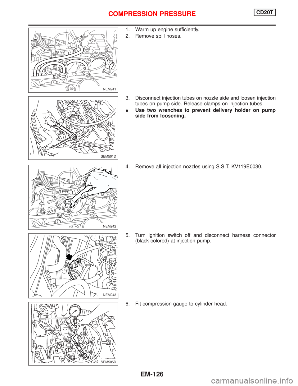
1. Warm up engine sufficiently.
2. Remove spill hoses.
3. Disconnect injection tubes on nozzle side and loosen injection
tubes on pump side. Release clamps on injection tubes.
IUse two wrenches to prevent delivery holder on pump
side from loosening.
4. Remove all injection nozzles using S.S.T. KV119E0030.
5. Turn ignition switch off and disconnect harness connector
(black colored) at injection pump.
6. Fit compression gauge to cylinder head.
NEM241
SEM501D
NEM242
NEM243
SEM505D
COMPRESSION PRESSURECD20T
EM-126
Page 1667 of 2267
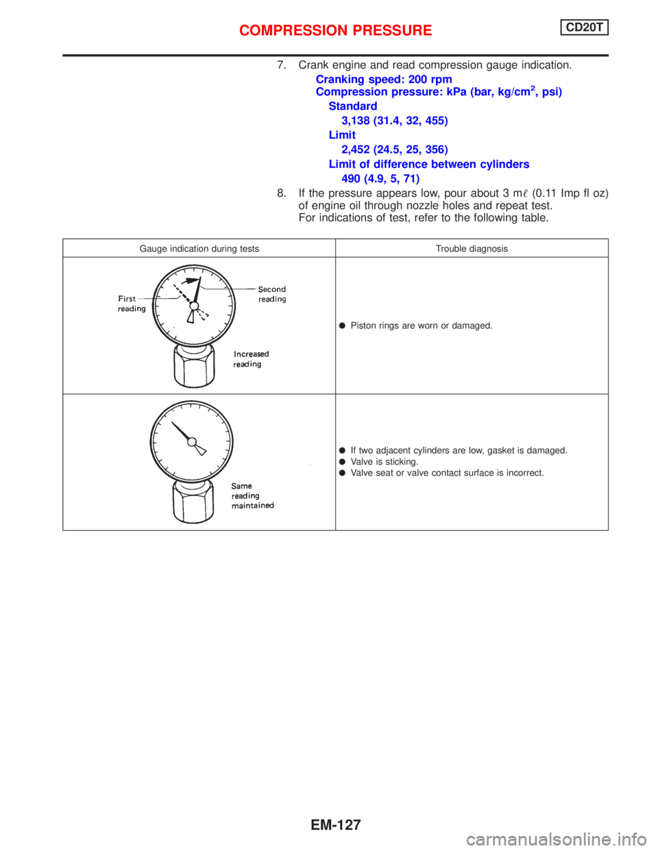
7. Crank engine and read compression gauge indication.
Cranking speed: 200 rpm
Compression pressure: kPa (bar, kg/cm
2, psi)
Standard
3,138 (31.4, 32, 455)
Limit
2,452 (24.5, 25, 356)
Limit of difference between cylinders
490 (4.9, 5, 71)
8. If the pressure appears low, pour about 3 m(0.11 Imp fl oz)
of engine oil through nozzle holes and repeat test.
For indications of test, refer to the following table.
Gauge indication during tests Trouble diagnosis
lPiston rings are worn or damaged.
lIf two adjacent cylinders are low, gasket is damaged.
lValve is sticking.
lValve seat or valve contact surface is incorrect.
COMPRESSION PRESSURECD20T
EM-127
Page 1668 of 2267
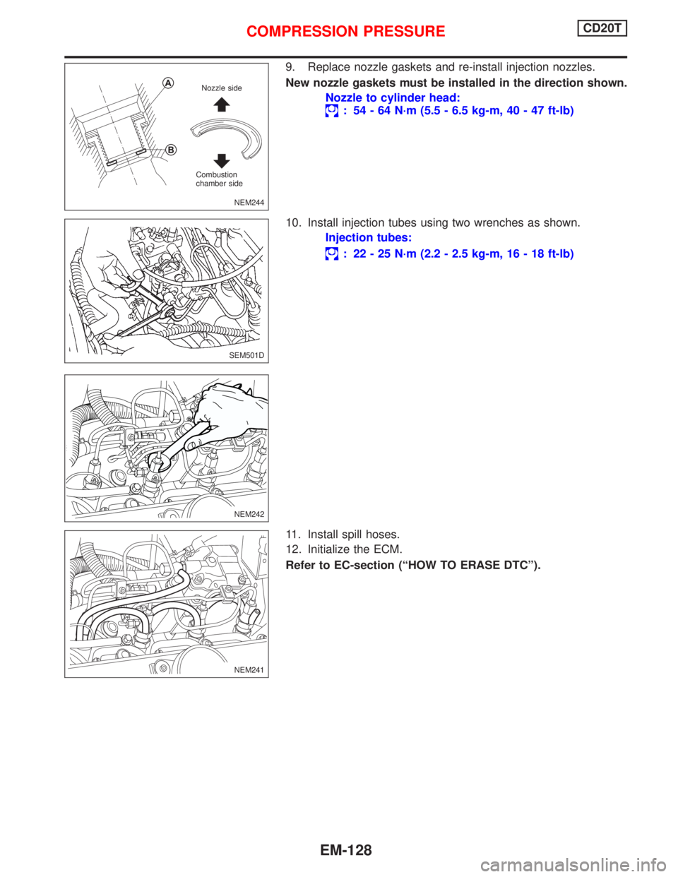
9. Replace nozzle gaskets and re-install injection nozzles.
New nozzle gaskets must be installed in the direction shown.
Nozzle to cylinder head:
: 54 - 64 N´m (5.5 - 6.5 kg-m, 40 - 47 ft-lb)
10. Install injection tubes using two wrenches as shown.
Injection tubes:
: 22 - 25 N´m (2.2 - 2.5 kg-m, 16 - 18 ft-lb)
11. Install spill hoses.
12. Initialize the ECM.
Refer to EC-section (ªHOW TO ERASE DTCº).
NEM244 Nozzle side
Combustion
chamber side
SEM501D
NEM242
NEM241
COMPRESSION PRESSURECD20T
EM-128
Page 1669 of 2267
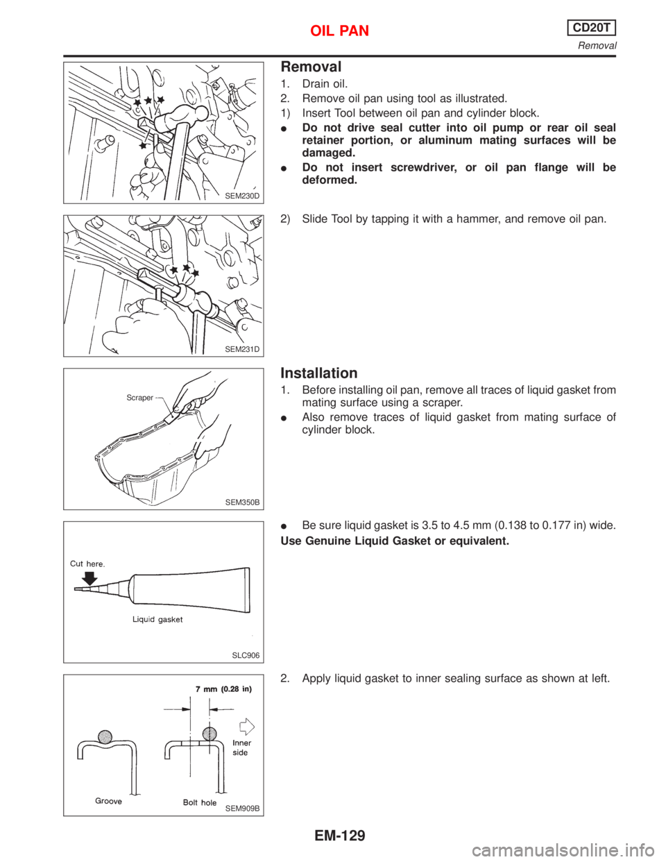
Removal
1. Drain oil.
2. Remove oil pan using tool as illustrated.
1) Insert Tool between oil pan and cylinder block.
IDo not drive seal cutter into oil pump or rear oil seal
retainer portion, or aluminum mating surfaces will be
damaged.
IDo not insert screwdriver, or oil pan flange will be
deformed.
2) Slide Tool by tapping it with a hammer, and remove oil pan.
Installation
1. Before installing oil pan, remove all traces of liquid gasket from
mating surface using a scraper.
IAlso remove traces of liquid gasket from mating surface of
cylinder block.
IBe sure liquid gasket is 3.5 to 4.5 mm (0.138 to 0.177 in) wide.
Use Genuine Liquid Gasket or equivalent.
2. Apply liquid gasket to inner sealing surface as shown at left.
SEM230D
SEM231D
SEM350B Scraper
SLC906
SEM909B
OIL PANCD20T
Removal
EM-129
Page 1670 of 2267
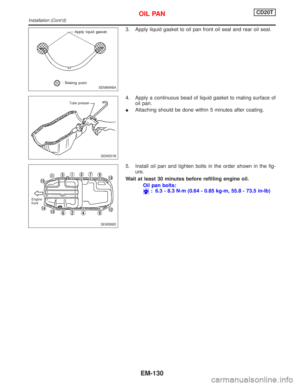
3. Apply liquid gasket to oil pan front oil seal and rear oil seal.
4. Apply a continuous bead of liquid gasket to mating surface of
oil pan.
IAttaching should be done within 5 minutes after coating.
5. Install oil pan and tighten bolts in the order shown in the fig-
ure.
Wait at least 30 minutes before refilling engine oil.
Oil pan bolts:
: 6.3 - 8.3 N´m (0.64 - 0.85 kg-m, 55.8 - 73.5 in-lb)
SEM894BA
SEM351B Tube presser
SEM369D Engine
front
OIL PANCD20T
Installation (Cont'd)
EM-130