NISSAN PULSAR 1987 Workshop Manual
Manufacturer: NISSAN, Model Year: 1987, Model line: PULSAR, Model: NISSAN PULSAR 1987Pages: 238, PDF Size: 28.91 MB
Page 201 of 238

Electrical System 201
nosed pliers. This will safeguard the diodes
by transferring any excess heat to the jaws of
the pliers.
Using a suitable drift, install the bearing into
the drive end bracket, install the retainer plate and
screws. Tighten the screws securely. Using a suitable press and press plates, install
the bearing to the slip ring end of the rotor shaft.
Ensure that pressure is ex erted only on the inner race
and that the stop ring groove is nearest to the sl i p
rings. Ensure that the rotor sh aft rear bearing stop
ring is positioned so that the protruding part of the
ring is located in the deepest part of the groove. Install the stator, diode pack and
regulator
assembly to the slip ring e nd bracket. Install the
retaining nuts and washers and tighten securely. Install the nut and insulator to the terminal
and tighten securely. Using a piece of wire, hold the brushes in a
retracted position. Hold the drive end bracket in a soft jawed
vice and install the rotor shaft assembly to the drive
end bracket. Install the pulley, retaining nut and washer to
the rotor shaft and tighten the retaining nut to the
specified torque. Apply a heated 200 watt soldering iron to the
slip ring end bracket at the bearing mounting boss for
3-4 minutes to heat the bracket and allow the
installation of the rotor shaft rear bearing. Aligning the marks made on dismantling and
ensuring that the rotor sh aft rear bearing retaining
ring protrusion is located in the deepest part of its
groove, install the rotor/stator assembly to the slip ring
end bracket.
Remove the brush retr acting wire from the
alternator, ensure that the alternator component
marks are aligned, install the retaining through bolts
and tighten them securely. Check the alternator rotor for smooth oper-
ation and install the al ternator to the vehicle
as
previously described.
Check the alternator operation on the vehicle
as previously described.
8. STARTER MOTOR
Special Equipment Required:
To Renew Brushes — Soldering iron
To Renew Armature Bearings — Bearing puller
DESCRIPTION
Two types of starter motors are installed to the
range of vehicles covere d by this manual, either
Hitachi or Bosch.
The starter motor is the induced pole type with
four brushes and four pole shoes with field coils.
A solenoid switch is attached to the starter drive
end bracket. The solenoid plunger is connected to
the overrunning clutch and drive pinion assembly
through a lever and pivot arrangement.
When the solenoid windings are energized, the
plunger acting on the lever and pivot engages the drive
pinion with the flywheel ri ng gear and at the same
time closes the switch supplying power from the
positive lead of the battery to the starter motor field
coils and armature to operate the motor.
As the engine fires, the over-running clutch of the
drive pinion assembly prevents high speed rotation of.
and possible damage to, the starter armature if the
solenoid windings are not immediately de-energized
by releasing the ignition key.
The starter solenoid switch windings are energized
by the ignition switch.
TO TEST ON VEHICLE
Should the starter motor fail to operate when the
ignition switch is turned to the Start position, check
the following points:
Check the battery condition and state of
charge. Refer to the Battery heading for the correct
procedure.
Clean the battery terminals, taking particular
care to remove the scale from the positive ( + )
terminal post and terminal. Check the earth connection for tightness and
cleanliness.
Switch on the headlamps and turn the igni-
tion switch to Start. If the lamps dim but the starter
motor does not operate, it could indicate that a short
circuit has developed in the starting system. Check that the engine is not seized or that the
starter motor drive pinion and ring gear are not
locked as these conditions would -give the same
indications as above.
(5) If the lamps do not dim and the starter
motor does not operate, this would indicate an open
circuit such as a broken or disconnected wire or a
switch not operating.
If the vehicle is equipped with an automatic
transaxle, turn the ignition switch to Start and move
the selector lever through all the gear selection range.
If the starter motor operates in any position other
than N or P, the neutral safety switch is faulty.
(6) Check all the external wiring to ensure that
the fault is not external. If the external circuit proves
satisfactory, indicating that the problem is in the
starter motor, the unit will have to be removed and
tested.
TO REMOVE AND INSTAL
Disconnect the negative battery terminal.
Disconnect the wiring from the starter motor
solenoid. Remove the starter motor mounting bolts,
Page 202 of 238
202 Electrical System
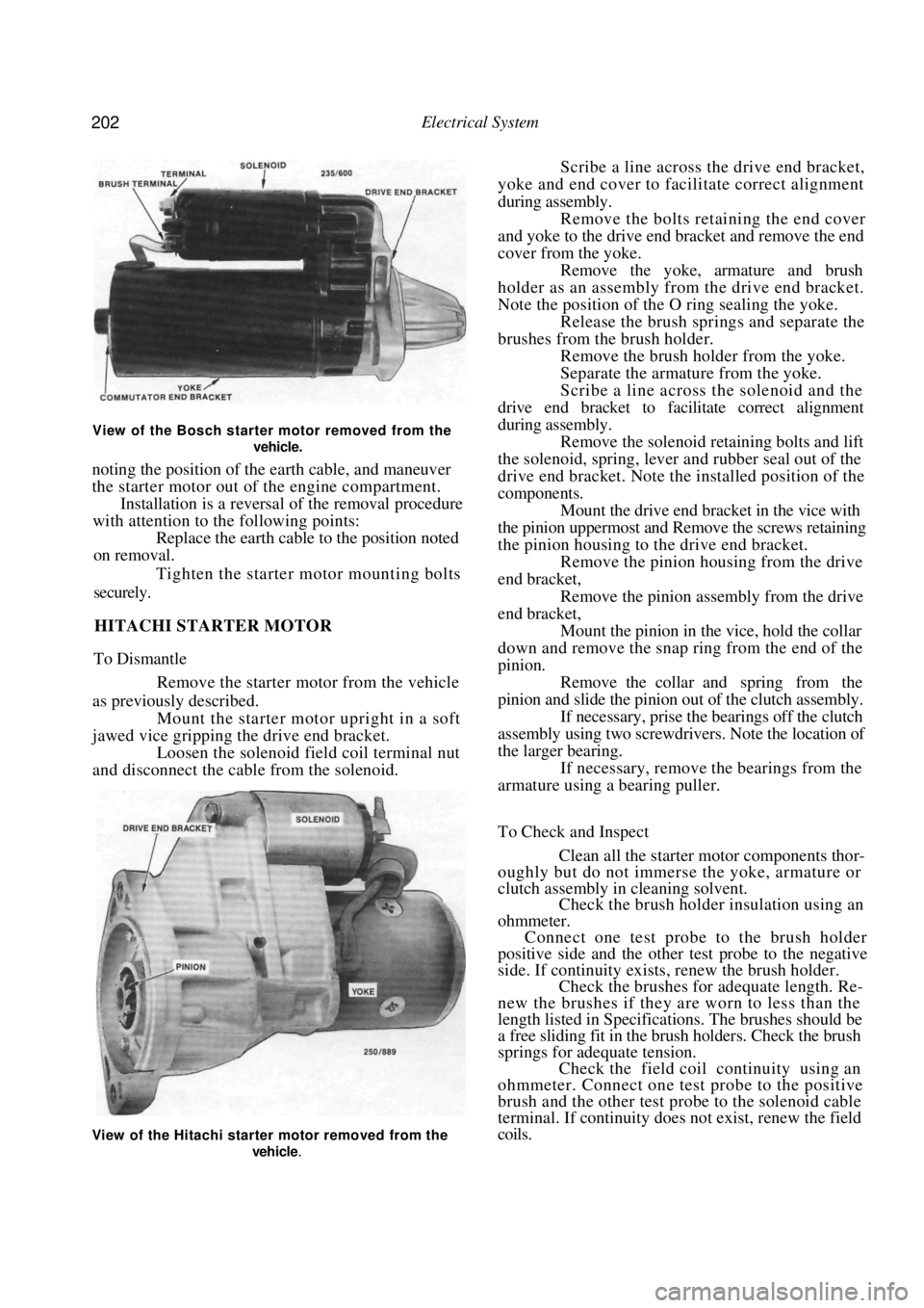
View of the Bosch starter motor removed from the
vehicle.
noting the position of the earth cable, and maneuver
the starter motor out of the engine compartment.
Installation is a reversal of the removal procedure
with attention to the following points:
Replace the earth cable to the position noted
on removal.
Tighten the starter motor mounting bolts
securely.
HITACHI STARTER MOTOR
To Dismantle
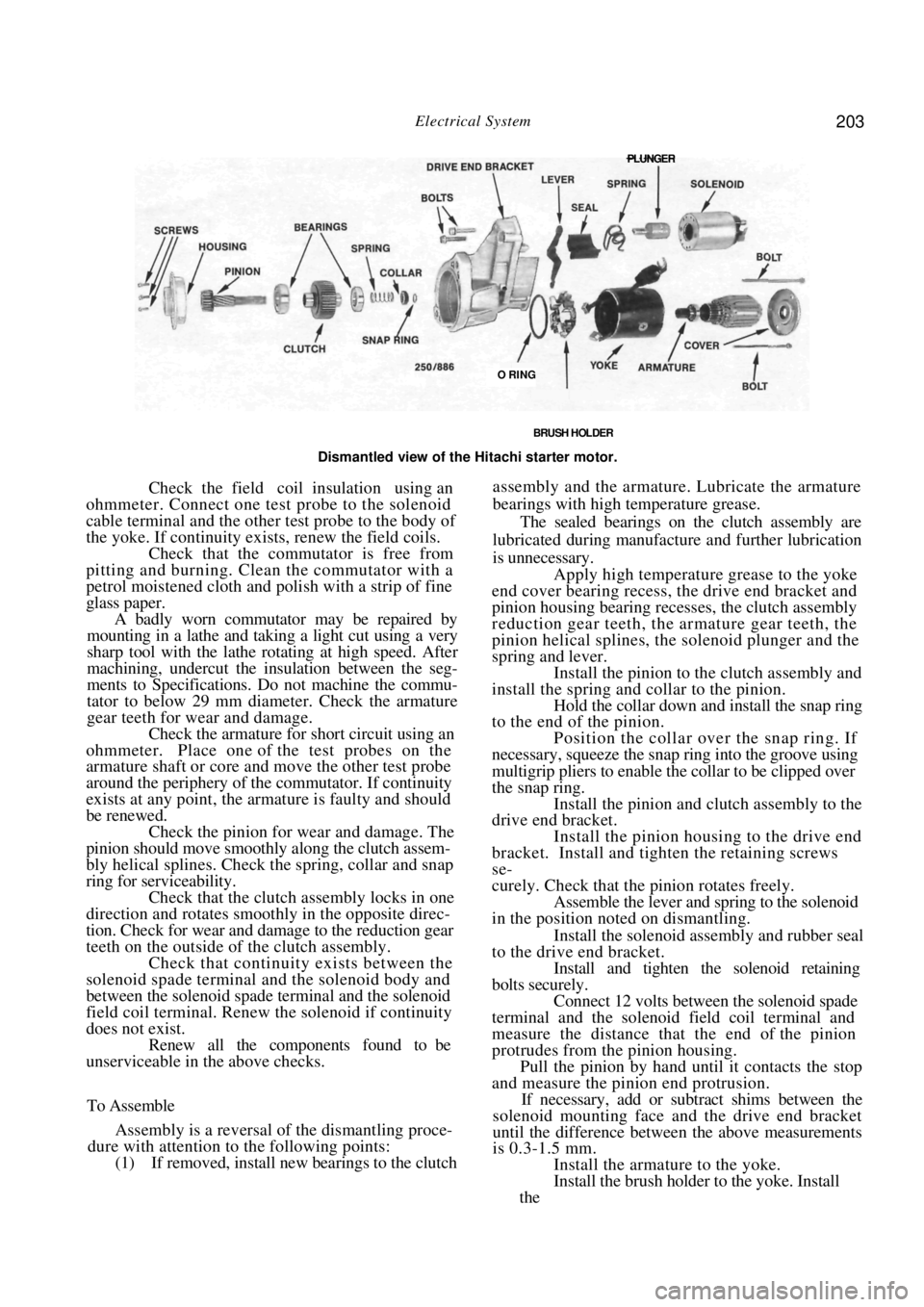
Remove the starter motor from the vehicle
as previously described. Mount the starter motor upright in a soft
jawed vice gripping the drive end bracket. Loosen the solenoid field coil terminal nut
and disconnect the cable from the solenoid.
Scribe a line across the drive end bracket,
yoke and end cover to facilitate correct alignment
during assembly. Remove the bolts retaining the end cover
and yoke to the drive end bracket and remove the end
cover from the yoke. Remove the yoke, armature and brush
holder as an assembly from the drive end bracket.
Note the position of the O ring sealing the yoke. Release the brush spri ngs and separate the
brushes from the brush holder. Remove the brush holder from the yoke.
Separate the armature from the yoke.
Scribe a line across the solenoid and the
drive end bracket to facilitate correct alignment
during assembly. Remove the solenoid retaining bolts and lift
the solenoid, spring, lever an d rubber seal out of the
drive end bracket. Note the installed position of the
components. Mount the drive end bracket in the vice with
the pinion uppermost and Remove the screws retaining
the pinion housing to the drive end bracket. Remove the pinion housing from the drive
end bracket,
Remove the pinion assembly from the drive
end bracket, Mount the pinion in the vice, hold the collar
down and remove the snap ring from the end of the
pinion. Remove the collar and spring from the
pinion and slide the pinion out of the clutch assembly. If necessary, prise the bearings off the clutch
assembly using two screwdri vers. Note the location of
the larger bearing. If necessary, remove the bearings from the
armature using a bearing puller.
To Check and Inspect
Clean all the starter motor components thor-
oughly but do not immerse the yoke, armature or
clutch assembly in cleaning solvent.
Check the brush holder insulation using an
ohmmeter. Connect one test probe to the brush holder
positive side and the other test probe to the negative
side. If continuity exists , renew the brush holder.
Check the brushes for adequate length. Re-
new the brushes if they are worn to less than the
length listed in Specifications. The brushes should be
a free sliding fit in the brush holders. Check the brush
springs for adequate tension.
Check the field coil continuity using an
ohmmeter. Connect one test probe to the positive
brush and the other test probe to the solenoid cable
terminal. If continuity does not exist, renew the field
coils.
View of the Hitachi starter motor removed from the
vehicle
.
Page 203 of 238
Electrical System 203
BRUSH HOLDER
Dismantled view of the Hitachi starter motor.
Check the field coil insulation using an
ohmmeter. Connect one test probe to the solenoid
cable terminal and the other test probe to the body of
the yoke. If continuity exists, renew the field coils. Check that the commutator is free from
pitting and burning. Clean the commutator with a
petrol moistened cloth and polish with a strip of fine
glass paper.
A badly worn commutator may be repaired by
mounting in a lathe and taking a light cut using a very
sharp tool with the lathe rotating at high speed. After
machining, undercut the insulation between the seg-
ments to Specifications. Do not machine the commu-
tator to below 29 mm diameter. Check the armature
gear teeth for wear and damage.
Check the armature for short circuit using an
ohmmeter. Place one of the test probes on the
armature shaft or core and move the other test probe
around the periphery of the commutator. If continuity
exists at any point, the armature is faulty and should
be renewed. Check the pinion for wear and damage. The
pinion should move smoothl y along the clutch assem-
bly helical splines. Check the spring, collar and snap
ring for serviceability.
Check that the clutch assembly locks in one
direction and rotates smoothly in the opposite direc-
tion. Check for wear and damage to the reduction gear
teeth on the outside of the clutch assembly.
Check that continuity exists between the
solenoid spade terminal and the solenoid body and
between the solenoid spade terminal and the solenoid
field coil terminal. Renew the solenoid if continuity
does not exist. Renew all the components found to be
unserviceable in the above checks.
To Assemble
Assembly is a reversal of the dismantling proce-
dure with attention to the following points:
(1) If removed, install new bearings to the clutch
assembly and the armature. Lubricate the armature
bearings with high temperature grease.
The sealed bearings on the clutch assembly are
lubricated during manufacture and further lubrication
is unnecessary.
Apply high temperature grease to the yoke
end cover bearing recess, the drive end bracket and
pinion housing bearing recesses, the clutch assembly
reduction gear teeth, the armature gear teeth, the
pinion helical splines, th e solenoid plunger and the
spring and lever. Install the pinion to the clutch assembly and
install the spring and collar to the pinion. Hold the collar down and install the snap ring
to the end of the pinion.
Position the collar over the snap ring. If
necessary, squeeze the snap ring into the groove using
multigrip pliers to enable the collar to be clipped over
the snap ring. Install the pinion and clutch assembly to the
drive end bracket.
Install the pinion housing to the drive end
bracket. Install and tighten the retaining screws
se-
curely. Check that the pinion rotates freely.
Assemble the lever and spring to the solenoid
in the position noted on dismantling.
Install the solenoid assembly and rubber seal
to the drive end bracket.
Install and tighten the solenoid retaining
bolts securely. Connect 12 volts between the solenoid spade
terminal and the solenoid field coil terminal and
measure the distance that the end of the pinion
protrudes from the pinion housing. Pull the pinion by hand until it contacts the stop
and measure the pinion end protrusion.
If necessary, add or subt ract shims between the
solenoid mounting face and the drive end bracket
until the difference between the above measurements
is 0.3-1.5 mm.
Install the armature to the yoke.
Install the brush holder to the yoke. Install
the
PLUNGER
O RING
Page 204 of 238

204 Electrical System
brushes to the brush holder and position the springs
against the ends of the brushes.
Install the O ring to the yoke taking care
that
the O ring is not twisted. Install the yoke, armature and brush
holder
assembly to the drive end bracket, aligning the marks
made on dismantling. Install the end cover to the yoke. Install
and
tighten the retaining bolts securely. Connect the cable to the solenoid field coil
terminal and tighten the terminal nut securely. Install the starter motor to the vehicle
as
previously described.
BOSCH STARTER MOTOR
To Dismantle
Disconnect the brush connector strap from
the lower terminal on the solenoid switch.
Remove the screws retaining the solenoid to
the drive end bracket and remove the solenoid from
the drive end bracket.
Loosen, but do not remove the screws retain-
ing the armature end cover to the commutator end
bracket. Remove the through bolts retaining the drive
end bracket to the commutator end bracket.
Remove the yoke, armature and commutator
end bracket from the drive end bracket as an assem-
bly. Hold the rubber seal in place in the drive end
bracket to keep the engaging lever in position.
Remove the rubber seal from the drive end
bracket. Remove the cover plate from the planetary
gear set and remove the gear set, drive assembly and
engaging lever as an assembly. Remove the armature end cover and com-
mutator end bracket from the yoke. Remove the screws retaining the armature
end cover to the commutator end cover and remove
the armature end cover, C clip and shims from the
armature shaft. Remove the commutator end bracket
from the armature. Carefully remove the brush holder from the
armature. Support the gear set and drive assembly in a
vertical position with the drive assembly uppermost.
Using a suitable drift, tap the stop collar
towards the drive assembly and remove the snap ring
from the drive shaft. Remove any burrs from the drive shaft and
withdraw the drive assembly and stop ring from the
drive shaft.
Clean all parts thoroughly but do not im-
merse the armature, solenoid or drive assembly in
cleaning solvent.
To Check and Inspect
(1) With the starter motor dismantled, check the
brush holder insulation using an ohmmeter.
Connect one test lead to the brush holder positive
BRACKET
Dismantled view of the Bosch starter motor.
Page 205 of 238

Electrical System 205
Dismantled view of the brush holder assembly. Bosch
starter motor.
side and the other lead to the negative side. If there is
any indication of leakage the ohmmeter will show a
reading other than infinity. Repair or renew the brush
holder if leakage is evident.
(2) Check the brushes for adequate length.
Brushes should be renewed when their length is below
Specifications. They should be a free sliding fit in the
brush holders.
NOTE: Due to the difficulty involved in
removing and installing the brushes in the
Bosch starter motor, it is recommended that
the brush holder be renewed as an assembly.
(3) Check that the commutator is free from
pitting and burning. Clean with a petrol moistened
cloth and polish with a strip of fine glass paper.
A badly worn commutator may be repaired by
mounting in a lathe, spi nning at high speed, and
taking a light cut with a very sharp tool. After turning,
undercut the insulation between the segments.
(4) Check the armature for short circuit using an
ohmmeter.
Place one of the test lead s on the armature shaft
or core and move the other lead around the circum-
ference of the commutator. If the ohmmeter shows a
reading at any point the armature is faulty and should
be renewed.
Check the drive assembly clutch pinion teeth
for wear, scoring or chipping. A clutch in good
condition should take up the drive in one direction
only. It should rotate easily and smoothly in the
non-drive direction and the assembly should move
smoothly along the armature or drive shaft helical
splines.
Check the armature shaft bushes for wear
and renew as necessary. The old bushes must be
removed and the new ones pressed into the end
brackets using a polished mandrel of the exact diam-
eter of the armature shaft. NOTE: The new bushes must not be reamed
to size, as reaming will impair the porosity
of the bushes and cause early failure. New
bushes should be allowed to stand immersed
in clean light engine oil for one hour before
installation.
To Assemble
Assembly is a reversal of the dismantling proce-
dure with attention to the following points:
Lubricate the helix of the drive shaft lightly
with graphite grease and install the drive assembly
to
the drive shaft. Install the stop collar and snap ring, slide the
stop collar over the snap ring to lock the snap ring in
position.
Lubricate the bushes in both end brackets
sparingly with engine oil. Install the engaging lever and gear set into the
drive end bracket. Install the centre rear bracket and the engag-
ing lever seal into the drive end bracket.
Slide the brush holder assembly into position
on the commutator ensuring that the brush holders
are correctly positioned in the anchor points. Install the commutator end bracket to
the
armature, install the shims and C clip. Check that the armature end float is satisfac-
tory and adjust as necessary using shims of the correct
thickness.
Align the slot in the commutator end bracket
with the cut out on the wiring seal and install the
armature end cover to the commutator end bracket.
Install the cover retaini ng screws but do not tighten.
Ensure that the permanent magnets in the
yoke have not picked up any debris and slide the yoke
over the armature ensuring that the wiring seal locates
correctly in the slot in the yoke.
View showing the planetary gear set. Bosch starter
motor.
Page 206 of 238
206 Electrical System
Install the armature and yoke to the drive end
bracket rotating the drive to align the reduction gears.
Do not use force.
Install the retaining through bolts to the
commutator end bracket and lighten the through bolts
and armature end cover retaining screws securely. Install the solenoid to the drive end bracket,
install the retaining screws and tighten them securely.
Install the brush connector strap and
install
the retaining nut and washer and tighten securely.
9 . IGNITION SYSTEM
The testing and repair procedures for the ignition
system are fully covered in the Fuel and Engine
Management section.
10. STEERING WHEEL
The removal and installation procedures for the
steering wheel and horn pad are fully covered in the
Steering section.
11. SWITCHES AND CONTROLS
IGNITION SWITCH
To Remove and Install
Disconnect the negative battery terminal.
Remove the retaining screws from the steer-
ing column cover. Unclip and separate the upper and lower
steering column covers and remove the upper cover. Release the column adjusting lever and re-
move the lower cover by guiding the column adjusting
lever through the hole in the upper end of the cover.
Disconnect the ignition switch wiring at the
switch. Remove the retaining screw and withdraw
the ignition switch fr om the lock assembly.
Installation is a reversal of the removal procedure.
COMBINATION SWITCH
The combination switch is mounted at the top of
the steering column and incorporates two switches.
The parking lamp, headlamp, headlamp flasher, head-
lamp dipper and turn signal lamps are operated by a
lever on the right hand side. A lever on the left hand
side operates the windscreen washer and wiper switch.
These switches can be re newed without removing
the combination switch.
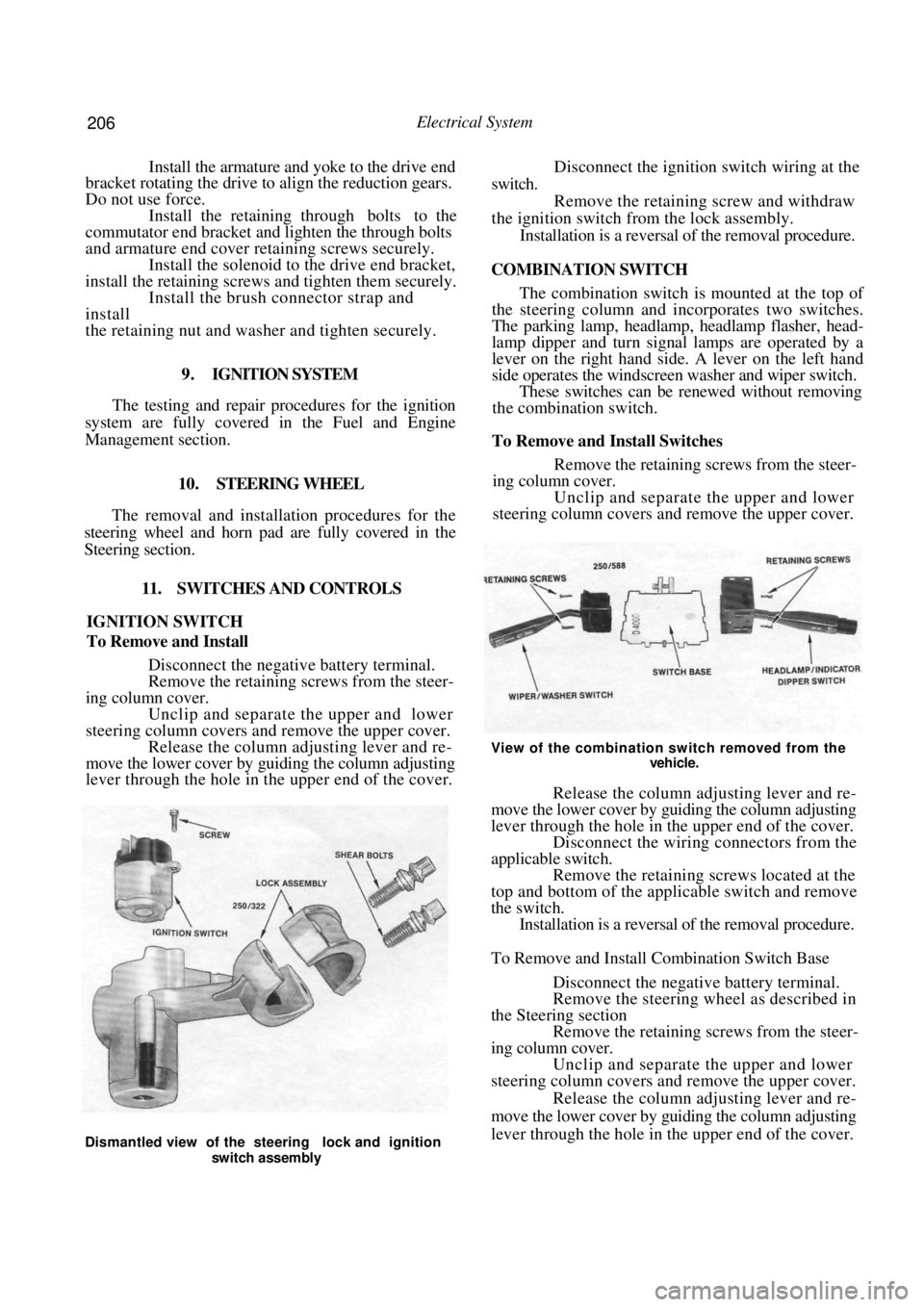
To Remove and Install Switches
Remove the retaining screws from the steer-
ing column cover.
Unclip and separate the upper and lower
steering column covers and remove the upper cover.
View of the combination switch removed from the
vehicle.
Release the column adjusting lever and re-
move the lower cover by guiding the column adjusting
lever through the hole in the upper end of the cover. Disconnect the wiring connectors from the
applicable switch. Remove the retaining screws located at the
top and bottom of the applicable switch and remove
the switch. Installation is a reversal of the removal procedure.
To Remove and Install Combination Switch Base
Disconnect the negative battery terminal.
Remove the steering wheel as described in
the Steering section Remove the retaining screws from the steer-
ing column cover. Unclip and separate the upper and lower
steering column covers and remove the upper cover.
Release the column adjusting lever and re-
move the lower cover by guiding the column adjusting
lever through the hole in the upper end of the cover.
Dismantled view of the steering lock and ignition
switch assembly
Page 207 of 238
Electrical System 207
Disconnect the wiring connectors from the
rear of the combination switch.
Loosen the clamping screw located at the left
hand side of the combination switch. Push, turn and slide the combination switch
from the steering column. Installation is a reversal of the removal procedure.
REAR WINDOW DEMISTER
SWITCH/HAZARD WARNING LAMP SWITCH
To Remove and Install
Disconnect the negative battery terminal.
Using two small flat bladed screwdrivers,
carefully lever the edges of the switch forward to
release it from the instrument cluster surround.
Withdraw the switch from the surround and
disconnect the switch wiri ng at the connectors.
Installation is a reversal of the removal procedure.
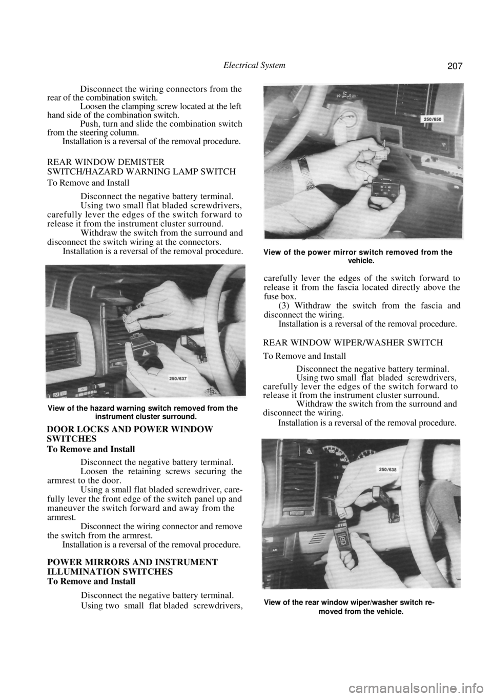
View of the hazard warning switch removed from the
instrument cluster surround.
DOOR LOCKS AND POWER WINDOW
SWITCHES
To Remove and Install
Disconnect the negative battery terminal.
Loosen the retaining screws securing the
armrest to the door. Using a small flat bladed screwdriver, care-
fully lever the front edge of the switch panel up and
maneuver the switch forward and away from the
armrest. Disconnect the wiring connector and remove
the switch from the armrest. Installation is a reversal of the removal procedure.
POWER MIRRORS AND INSTRUMENT
ILLUMINATION SWITCHES
To Remove and Install
Disconnect the negative battery terminal.
Using two small flat bladed screwdrivers,
View of the power mirror switch removed from the
vehicle.
carefully lever the edges of the switch forward to
release it from the fascia lo cated directly above the
fuse box.
(3) Withdraw the switch from the fascia and
disconnect the wiring.
Installation is a reversal of the removal procedure.
REAR WINDOW WIPER/WASHER SWITCH
To Remove and Install
Disconnect the negative battery terminal.
Using two small flat bladed screwdrivers,
carefully lever the edges of the switch forward to
release it from the instrument cluster surround. Withdraw the switch from the surround and
disconnect the wiring.
Installation is a reversal of the removal procedure.
View of the rear window wiper/washer switch re-
moved from the vehicle.
Page 208 of 238
208 Electrical System
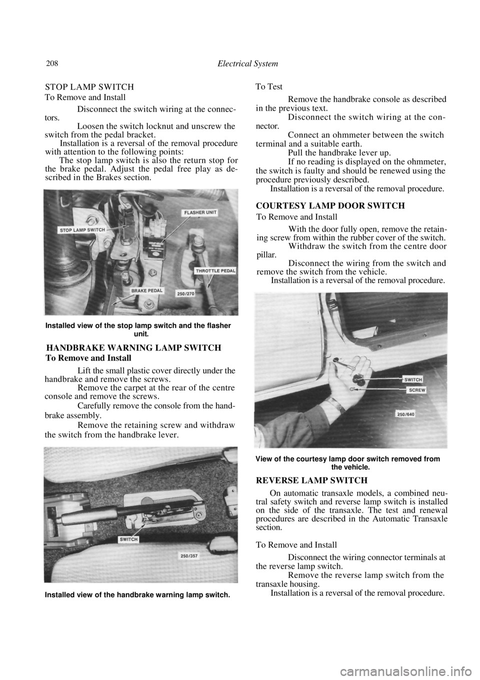
STOP LAMP SWITCH
To Remove and Install
Disconnect the switch wi ring at the connec-
tors.
Loosen the switch locknut and unscrew the
switch from the pedal bracket.
Installation is a reversal of the removal procedure
with attention to the following points:
The stop lamp switch is also the return stop for
the brake pedal. Adjust the pedal free play as de-
scribed in the Brakes section.
Installed view of the stop lamp switch and the flasher
unit.
HANDBRAKE WARNING LAMP SWITCH
To Remove and Install
Lift the small plastic cover directly under the
handbrake and remove the screws.
Remove the carpet at the rear of the centre
console and remove the screws.
Carefully remove the console from the hand-
brake assembly. Remove the retaining screw and withdraw
the switch from the handbrake lever. To Test
Remove the handbrake console as described
in the previous text.
Disconnect the switch wiring at the con-
nector. Connect an ohmmeter between the switch
terminal and a suitable earth. Pull the handbrake lever up.
If no reading is displayed on the ohmmeter,
the switch is faulty and should be renewed using the
procedure previously described. Installation is a reversal of the removal procedure.
COURTESY LAMP DOOR SWITCH
To Remove and Install
With the door fully open, remove the retain-
ing screw from within the rubber cover of the switch. Withdraw the switch from the centre door
pillar.
Disconnect the wiring from the switch and
remove the switch from the vehicle. Installation is a reversal of the removal procedure.
View of the courtesy lamp door switch removed from
the vehicle.
REVERSE LAMP SWITCH
On automatic transaxle models, a combined neu-
tral safety switch and reverse lamp switch is installed
on the side of the transaxle. The test and renewal
procedures are described in the Automatic Transaxle
section.
To Remove and Install
Disconnect the wiring connector terminals at
the reverse lamp switch. Remove the reverse lamp switch from the
transaxle housing. Installation is a reversal of the removal procedure.
Installed view of the handbrake warning lamp switch.
Page 209 of 238

Electrical System 209
12. INSTRUMENT CLUSTER
TO REMOVE AND INSTAL
Disconnect the negative battery terminal.
Remove the retaining screws from the instru-
ment cluster surround. Carefully withdraw the instrument cluster
surround from the instrument panel sufficiently to
enable the wiring to be disconnected. Remove the
surround from the vehicle.
.
FLEXIBLE PRINTED
CIRCUIT
Rear view of the instrument cluster removed from the
vehicle.
(4) Remove the instrument cluster assembly
retaining screws and gently ease the assembly from the
instrument panel sufficiently to enable the wiring to be
disconnected.
If necessary, remove the instruments as follows:
Carefully depress the retaining clips on the
front lens and remove the front lens. On models equipped with a tachometer, slide
the plastic rib from between the speedometer and the
tachometer. Remove the screws retaining the speedome-
ter and the tachometer or fuel/temperature gauges
from the rear of the instrument cluster.
CLUSTER ASSEMBLY
(d) Withdraw both instruments from the front of
the instrument cluster being careful as these instru-
ments are held by protruding pin terminals.
NOTE: Do not touch the faces of the instru-
ment dials as they mark easily.
(e) On models equipped with a tachometer,
remove the retaining nuts and remove the tempera-
ture and/or the fuel gauge from the cluster assembly.
Installation is a reversal of the removal procedure
ensuring that all electrical connectors are correctly
installed.
13. BLOWER FAN
The removal and installation procedure for the
blower fan is described in the Cooling and Heating
Systems section.
14. RADIO/CASSETTE
TO REMOVE AND INSTAL
Disconnect the negative battery terminal.
Remove the release hole covers on each side
of the radio/cassette.
Dismantled view of the instrument cluster.
Illustration of the radio/cass ette removal tool showing
the required dimensions.
BULB HOLDERS
BULB HOLDERS
Removing the release hole covers from the radio/cas-
sette.
Page 210 of 238
210 Electrical System
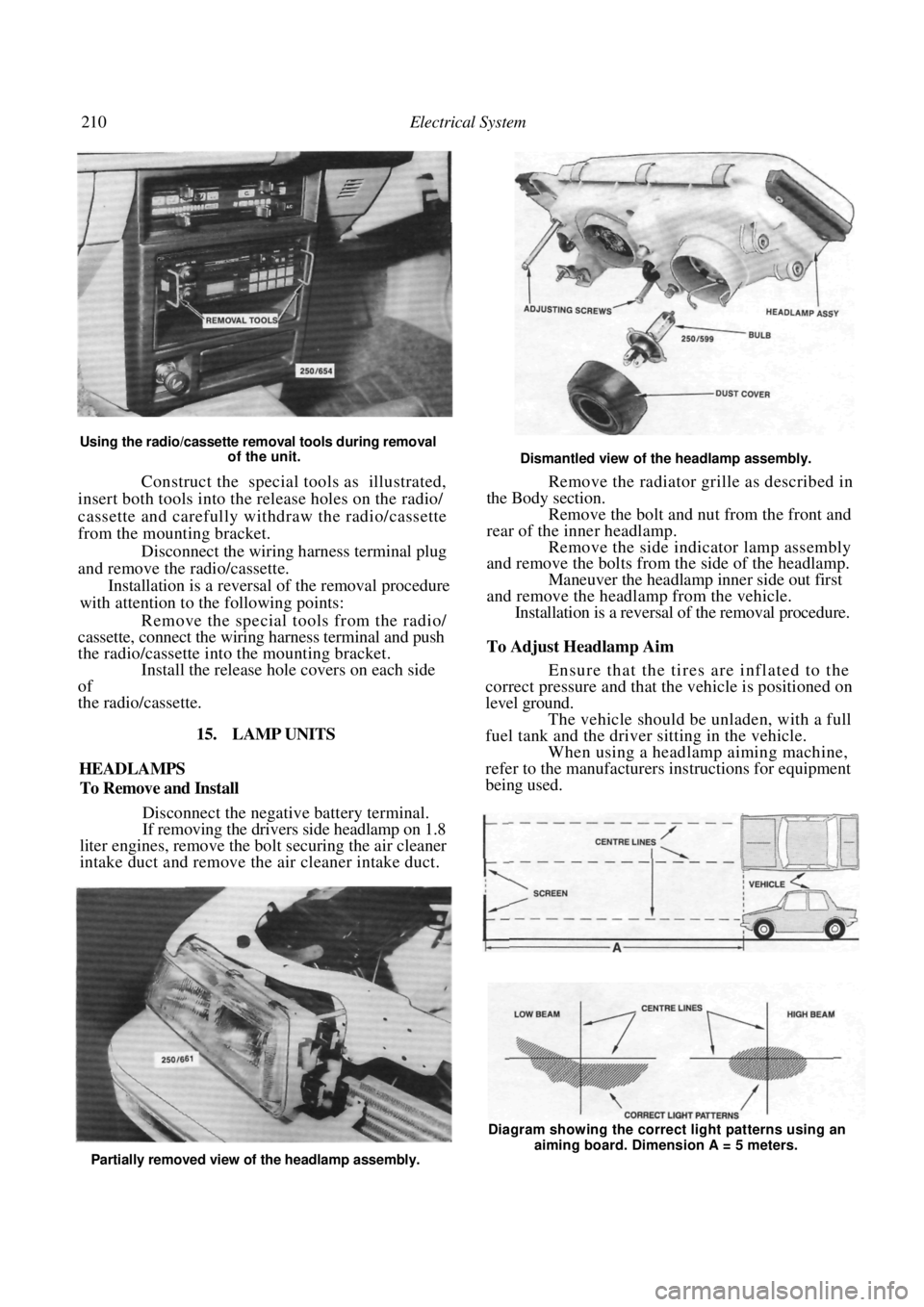
Using the radio/cassette removal tools during removal of the unit.
Construct the special tools as illustrated,
insert both tools into the release holes on the radio/
cassette and carefully withdraw the radio/cassette
from the mounting bracket.
Disconnect the wiring harness terminal plug
and remove the radio/cassette.
Installation is a reversal of the removal procedure
with attention to the following points:
Remove the special tools from the radio/
cassette, connect the wiring harness terminal and push
the radio/cassette into the mounting bracket. Install the release hole covers on each side
of
the radio/cassette.
15. LAMP UNITS
HEADLAMPS
To Remove and Install
Disconnect the negative battery terminal.
If removing the drivers side headlamp on 1.8
liter engines, remove the bo lt securing the air cleaner
intake duct and remove the air cleaner intake duct.
Dismantled view of the headlamp assembly.
Remove the radiator grille as described in
the Body section. Remove the bolt and nut from the front and
rear of the inner headlamp. Remove the side indicator lamp assembly
and remove the bolts from the side of the headlamp.
Maneuver the headlamp inner side out first
and remove the headlamp from the vehicle. Installation is a reversal of the removal procedure.
To Adjust Headlamp Aim
Ensure that the tires are inflated to the
correct pressure and that the vehicle is positioned on
level ground.
The vehicle should be unladen, with a full
fuel tank and the driver sitting in the vehicle. When using a headlamp aiming machine,
refer to the manufacturers instructions for equipment
being used.
Partially removed view of the headlamp assembly. Diagram showing the correct light patterns using an
aiming board. Dimension A = 5 meters.