wheel torque NISSAN TEANA 2008 Owner's Manual
[x] Cancel search | Manufacturer: NISSAN, Model Year: 2008, Model line: TEANA, Model: NISSAN TEANA 2008Pages: 5121, PDF Size: 69.03 MB
Page 2492 of 5121

FSU-18
< SERVICE DATA AND SPECIFICATIONS (SDS)
SERVICE DATA AND SPECIFICATIONS (SDS)
SERVICE DATA AND SPECIFICATIONS (SDS)
SERVICE DATA AND SPECIFICATIONS (SDS)
Wheel AlignmentINFOID:0000000003811129
Measure value under unladen* conditions.
*: Fuel, engine coolant and lubricant are full. Spare tire, jack, hand tools and mats are in designated positions.
Ball JointINFOID:0000000003811130
Wheel HeightINFOID:0000000003811131
Item Standard
Camber
Degree minute (Decimal degree)Minimum –1° 10′ (–1.16°)
Nominal –0° 25′ (–0.42°)
Maximum 0° 20′ (0.33°)
Left and right difference 0° 45′ (0.75°) or less
Caster
Degree minute (Decimal degree)Minimum 4° 10′ (4.17°)
Nominal 4° 55′ (4.92°)
Maximum 5° 40′ (5.66°)
Left and right difference 0° 45′ (0.75°) or less
Kingpin inclination
Degree minute (Decimal degree)Minimum 11° 55′ (11.92°)
Nominal 12° 40′ (12.67°)
Maximum 13° 25′ (13.41°)
To t a l t o e -
inDistanceMinimum In 0.5 mm (0.020 in)
Nominal In 1.5 mm (0.059 in)
Maximum In 2.5 mm (0.098 in)
Angle (left wheel or right wheel)
Degree minute (Decimal degree)Minimum In 0° 02′ (0.04°)
Nominal In 0° 04
′ (0.07°)
Maximum In 0° 06′ (0.10°)
Item Standard
Swing torque Transverse link 0.5 – 4.9 N·m (0.06 – 0.49 kg-m, 5 – 43 in-lb)
Measurement on spring balance Transverse link 11.1 – 108.9 N (1.2 – 11.1 kg, 3 – 24 lb)
Rotating torque Transverse link 0.5 – 3.4 N·m (0.06 – 0.34 kg-m, 5 – 30 in-lb)
Axial end play0.1 mm (0.004 in)
Tire size 205/65R16 215/55R17
Engine VQ25DE VQ35DE
Grade 250XE 250XL-V6 250XV-V6 350XV-V6
Front (Hf) 712 mm (28.03 in) 711 mm (27.99 in) 710 mm (27.95 in)
Page 2494 of 5121
GI-1
GENERAL INFORMATION
C
D
E
F
G
H
I
J
K
L
MB
GI
SECTION GI
N
O
P
CONTENTS
GENERAL INFORMATION
HOW TO USE THIS MANUAL ......................3
HOW TO USE THIS MANUAL ............................3
Description ................................................................3
Terms ........................................................................3
Units ..........................................................................3
Contents ....................................................................3
Relation between Illustrations and Descriptions .......4
Components ..............................................................4
HOW TO FOLLOW TROUBLE DIAGNOSES .....6
Description ................................................................6
How to Follow Test Groups in Trouble Diagnosis ......6
Key to Symbols Signifying Measurements or Pro-
cedures .....................................................................
7
HOW TO READ WIRING DIAGRAMS ................9
Connector Symbols ...................................................9
Sample/Wiring Diagram -Example- .........................10
Description ..............................................................11
ABBREVIATIONS ..............................................13
Abbreviation List ......................................................13
TIGHTENING TORQUE OF STANDARD
BOLTS ................................................................
14
Description ..............................................................14
Tightening Torque Table (New Standard Includ-
ed) ...........................................................................
14
TERMINOLOGY .................................................17
SAE J1930 Terminology List ...................................17
FEATURES OF NEW MODEL .....................21
IDENTIFICATION INFORMATION .....................21
Model Variation .......................................................21
Information About Identification or Model Code ......21
Dimensions .............................................................23
Wheels & Tires ........................................................23
PRECAUTION ..............................................24
PRECAUTIONS .................................................24
Description ...............................................................24
Precaution for Supplemental Restraint System
(SRS) "AIR BAG" and "SEAT BELT PRE-TEN-
SIONER" .................................................................
24
Precautions For Xenon Headlamp Service .............24
Precaution Necessary for Steering Wheel Rota-
tion after Battery Disconnect ...................................
24
Precaution for Procedure without Cowl Top Cover ....25
General Precautions ................................................25
Three Way Catalyst .................................................27
Multiport Fuel Injection System or Engine Control
System .....................................................................
27
Hoses ......................................................................27
Engine Oils ..............................................................28
Air Conditioning .......................................................28
Fuel ..........................................................................29
LIFTING POINT .................................................30
Commercial Service Tools .......................................30
Garage Jack and Safety Stand and 2-Pole Lift .......30
Board-On Lift ...........................................................31
TOW TRUCK TOWING .....................................32
Tow Truck Towing ...................................................32
Vehicle Recovery (Freeing a Stuck Vehicle) ...........32
BASIC INSPECTION ...................................34
SERVICE INFORMATION FOR ELECTRICAL
INCIDENT ..........................................................
34
Work Flow ................................................................34
Control Units and Electrical Parts ............................34
Intermittent Incident .................................................35
Circuit Inspection .....................................................37
CONSULT-III/GST CHECKING SYSTEM .........43
Description ...............................................................43
CONSULT-III Function and System Application*1 ....43
CONSULT-III/GST Data Link Connector (DLC)
Circuit ......................................................................
43
Page 3223 of 5121
CHASSIS MAINTENANCE
MA-35
< ON-VEHICLE MAINTENANCE >
C
D
E
F
G
H
I
J
K
L
MB
MAN
OA
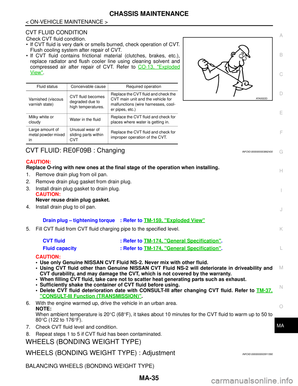
CVT FLUID CONDITION
Check CVT fluid condition.
If CVT fluid is very dark or smells burned, check operation of CVT.
Flush cooling system after repair of CVT.
If CVT fluid contains frictional material (clutches, brakes, etc.),
replace radiator and flush cooler line using cleaning solvent and
compressed air after repair of CVT. Refer to CO-13, "
Exploded
View".
CVT FLUID: RE0F09B : ChangingINFOID:0000000003862430
CAUTION:
Replace O-ring with new ones at the final stage of the operation when installing.
1. Remove drain plug from oil pan.
2. Remove drain plug gasket from drain plug.
3. Install drain plug gasket to drain plug.
CAUTION:
Never reuse drain plug gasket.
4. Install drain plug to oil pan.
5. Fill CVT fluid from CVT fluid charging pipe to the specified level.
CAUTION:
Use only Genuine NISSAN CVT Fluid NS-2. Never mix with other fluid.
Using CVT fluid other than Genuine NISSAN CVT Fluid NS-2 will deteriorate in driveability and
CVT durability, and may damage the CVT, which is not covered by the warranty.
When filling CVT fluid, take care not to scatter heat generating parts such as exhaust.
Sufficiently shake the container of CVT fluid before using.
Delete CVT fluid deterioration date with CONSULT-III after changing CVT fluid. Refer to TM-37,
"CONSULT-III Function (TRANSMISSION)".
6. With the engine warmed up, drive the vehicle in an urban area.
NOTE:
When ambient temperature is 20°C (68°F), it takes about 10 minutes for the CVT fluid to warm up to 50 to
80°C (122 to 176°F).
7. Check CVT fluid level and condition.
8. Repeat steps 1 to 5 if CVT fluid has been contaminated.
WHEELS (BONDING WEIGHT TYPE)
WHEELS (BONDING WEIGHT TYPE) : AdjustmentINFOID:0000000003911590
BALANCING WHEELS (BONDING WEIGHT TYPE)
Fluid status Conceivable cause Required operation
Varnished (viscous
varnish state)CVT fluid becomes
degraded due to
high temperatures.Replace the CVT fluid and check the
CVT main unit and the vehicle for
malfunctions (wire harnesses, cool-
er pipes, etc.)
Milky white or
cloudyWater in the fluidReplace the CVT fluid and check for
places where water is getting in.
Large amount of
metal powder mixed
inUnusual wear of
sliding parts within
CVTReplace the CVT fluid and check for
improper operation of the CVT.
ATA0022D
Drain plug – tightening torque : Refer to TM-159, "Exploded View"
CVT fluid : Refer to TM-174, "General Specification".
Fluid capacity : Refer to TM-174, "
General Specification".
Page 3225 of 5121
CHASSIS MAINTENANCE
MA-37
< ON-VEHICLE MAINTENANCE >
C
D
E
F
G
H
I
J
K
L
MB
MAN
OA
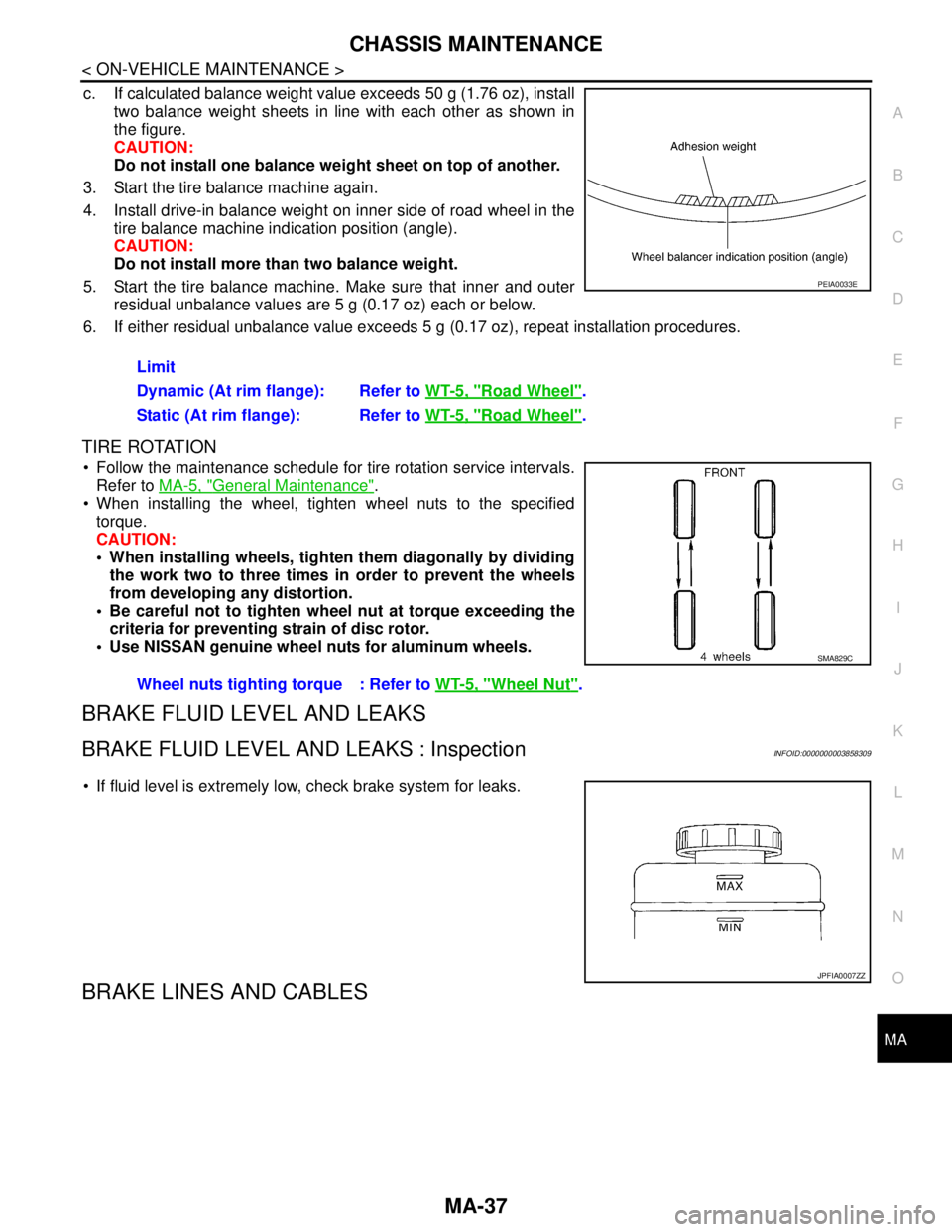
c. If calculated balance weight value exceeds 50 g (1.76 oz), install
two balance weight sheets in line with each other as shown in
the figure.
CAUTION:
Do not install one balance weight sheet on top of another.
3. Start the tire balance machine again.
4. Install drive-in balance weight on inner side of road wheel in the
tire balance machine indication position (angle).
CAUTION:
Do not install more than two balance weight.
5. Start the tire balance machine. Make sure that inner and outer
residual unbalance values are 5 g (0.17 oz) each or below.
6. If either residual unbalance value exceeds 5 g (0.17 oz), repeat installation procedures.
TIRE ROTATION
Follow the maintenance schedule for tire rotation service intervals.
Refer to MA-5, "
General Maintenance".
When installing the wheel, tighten wheel nuts to the specified
torque.
CAUTION:
When installing wheels, tighten them diagonally by dividing
the work two to three times in order to prevent the wheels
from developing any distortion.
Be careful not to tighten wheel nut at torque exceeding the
criteria for preventing strain of disc rotor.
Use NISSAN genuine wheel nuts for aluminum wheels.
BRAKE FLUID LEVEL AND LEAKS
BRAKE FLUID LEVEL AND LEAKS : InspectionINFOID:0000000003858309
If fluid level is extremely low, check brake system for leaks.
BRAKE LINES AND CABLES
Limit
Dynamic (At rim flange): Refer to WT-5, "
Road Wheel".
Static (At rim flange): Refer to WT-5, "
Road Wheel".
PEIA0033E
Wheel nuts tighting torque : Refer to WT-5, "Wheel Nut".
SMA829C
JPFIA0007ZZ
Page 3730 of 5121
REAR WHEEL HUB AND HOUSING
RAX-5
< ON-VEHICLE REPAIR >
C
E
F
G
H
I
J
K
L
MA
B
RAX
N
O
P
Temporarily tighten nuts to prevent damage to threads and to prevent the ball joint remover from
coming off.
16. Remove hub cap.
INSTALLATION
Note the following, and install in the reverse order of removal.
Perform the final tightening of each of parts under unladen conditions, which were removed when removing
wheel hub and bearing assembly and steering knuckle.
Never reuse cotter pin.
InspectionINFOID:0000000003811101
INSPECTION AFTER REMOVAL
Wheel Hub and Bearing Assembly
Check the wheel hub and bearing assembly for wear, cracks, and damage. Replace if necessary.
Axle Housing
Check the axle housing for wear, cracks, and damage. Replace if necessary.
Ball Joint Inspection
Check for boot breakage, axial looseness, and torque of suspension arm ball joint. Refer to RSU-16, "Inspec-
tion".
INSPECTION AFTER INSTALLATION
1. Check wheel sensor harness for proper connection. Refer to BRC-58, "REAR WHEEL SENSOR :
Exploded View" (without VDC), BRC-152, "REAR WHEEL SENSOR : Exploded View" (with VDC).
2. Adjust parking brake operation (stroke). Refer to PB-2, "
Inspection and Adjustment".
3. Check wheel alignment. Refer to RSU-6, "
Inspection".
4. Adjust neutral position of steering angle sensor (with VDC). Refer to BRC-66, "
ADJUSTMENT OF
STEERING ANGLE SENSOR NEUTRAL POSITION : Special Repair Requirement".
Page 3839 of 5121
WHEEL ALIGNMENT
RSU-7
< ON-VEHICLE MAINTENANCE >
C
D
F
G
H
I
J
K
L
MA
B
RSU
N
O
P
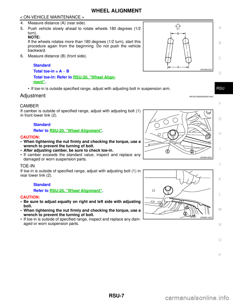
4. Measure distance (A) (rear side).
5. Push vehicle slowly ahead to rotate wheels 180 degrees (1/2
turn).
NOTE:
If the wheels rotates more than 180 degrees (1/2 turn), start this
procedure again from the beginning. Do not push the vehicle
backward.
6. Measure distance (B) (front side).
If toe-in is outside specified range, adjust with adjusting bolt in suspension arm.
AdjustmentINFOID:0000000003813443
CAMBER
If camber is outside of specified range, adjust with adjusting bolt (1)
in front lower link (2).
CAUTION:
When tightening the nut firmly and checking the torque, use a
wrench to prevent the turning of bolt.
After adjusting camber, be sure to check toe-in.
If camber exceeds the standard value, inspect and replace any
damaged or worn suspension parts.
TOE-IN
If toe-in is outside of specified range, adjust with adjusting bolt (1) in
rear lower link (2).
CAUTION:
Be sure to adjust equally on right and left side with adjusting
bolt.
When tightening the nut firmly and checking the torque, use a
wrench to prevent the turning of bolt.
If toe-in is outside of specified range, inspect and replace any dam-
aged or worn suspension parts.Standard
Total toe-in = A − B
Total toe-in: Refer to RSU-20, "
Wheel Align-
ment".
JPEIA0015ZZ
Standard
Refer to RSU-20, "
Wheel Alignment".
JPEIB0109ZZ
Standard
Refer to RSU-20, "
Wheel Alignment".
JPEIB0110ZZ
Page 3849 of 5121
REAR SUSPENSION ARM
RSU-17
< REMOVAL AND INSTALLATION >
C
D
F
G
H
I
J
K
L
MA
B
RSU
N
O
P
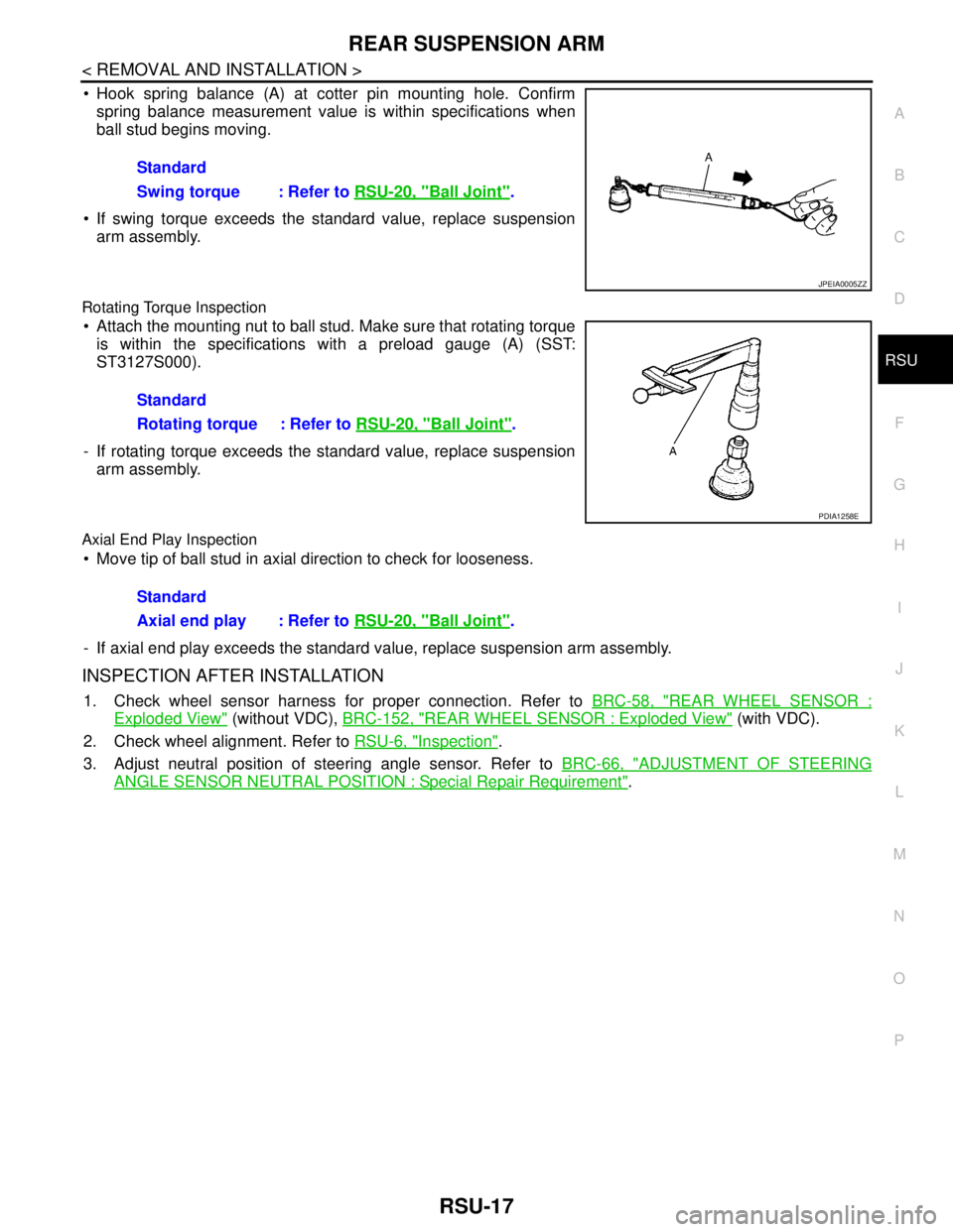
Hook spring balance (A) at cotter pin mounting hole. Confirm
spring balance measurement value is within specifications when
ball stud begins moving.
If swing torque exceeds the standard value, replace suspension
arm assembly.
Rotating Torque Inspection
Attach the mounting nut to ball stud. Make sure that rotating torque
is within the specifications with a preload gauge (A) (SST:
ST3127S000).
- If rotating torque exceeds the standard value, replace suspension
arm assembly.
Axial End Play Inspection
Move tip of ball stud in axial direction to check for looseness.
- If axial end play exceeds the standard value, replace suspension arm assembly.
INSPECTION AFTER INSTALLATION
1. Check wheel sensor harness for proper connection. Refer to BRC-58, "REAR WHEEL SENSOR :
Exploded View" (without VDC), BRC-152, "REAR WHEEL SENSOR : Exploded View" (with VDC).
2. Check wheel alignment. Refer to RSU-6, "
Inspection".
3. Adjust neutral position of steering angle sensor. Refer to BRC-66, "
ADJUSTMENT OF STEERING
ANGLE SENSOR NEUTRAL POSITION : Special Repair Requirement". Standard
Swing torque : Refer to RSU-20, "
Ball Joint".
JPEIA0005ZZ
Standard
Rotating torque : Refer to RSU-20, "
Ball Joint".
PDIA1258E
Standard
Axial end play : Refer to RSU-20, "
Ball Joint".
Page 3852 of 5121
RSU-20
< SERVICE DATA AND SPECIFICATIONS (SDS)
SERVICE DATA AND SPECIFICATIONS (SDS)
SERVICE DATA AND SPECIFICATIONS (SDS)
SERVICE DATA AND SPECIFICATIONS (SDS)
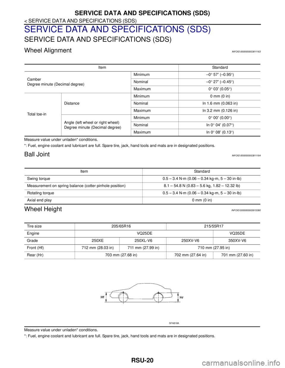
Wheel AlignmentINFOID:0000000003811163
Measure value under unladen* conditions.
*: Fuel, engine coolant and lubricant are full. Spare tire, jack, hand tools and mats are in designated positions.
Ball JointINFOID:0000000003811164
Wheel HeightINFOID:0000000003815380
Measure value under unladen* conditions.
*: Fuel, engine coolant and lubricant are full. Spare tire, jack, hand tools and mats are in designated positions.Item Standard
Camber
Degree minute (Decimal degree)Minimum –0° 57′ (–0.95°)
Nominal –0° 27′ (–0.45°)
Maximum 0° 03′ (0.05°)
To t a l t o e - i nDistanceMinimum 0 mm (0 in)
Nominal In 1.6 mm (0.063 in)
Maximum In 3.2 mm (0.126 in)
Angle (left wheel or right wheel)
Degree minute (Decimal degree)Minimum 0° 00′ (0.00°)
Nominal In 0° 04′ (0.07°)
Maximum In 0° 08′ (0.13°)
Item Standard
Swing torque 0.5 – 3.4 N·m (0.06 – 0.34 kg-m, 5 – 30 in-lb)
Measurement on spring balance (cotter pinhole position) 8.1 – 54.8 N (0.83 – 5.6 kg, 1.82 – 12.32 lb)
Rotating torque 0.5 – 3.4 N·m (0.06 – 0.34 kg-m, 5 – 30 in-lb)
Axial end play0 mm (0 in)
Tire size 205/65R16 215/55R17
Engine VQ25DE VQ35DE
Grade 250XE 250XL-V6 250XV-V6 350XV-V6
Front (Hf) 712 mm (28.03 in) 711 mm (27.99 in) 710 mm (27.95 in)
Rear (Hr) 703 mm (27.68 in) 702 mm (27.64 in) 701 mm (27.60 in)
SFA818A
Page 4391 of 5121
ST-1
STEERING
C
DE
F
H I
J
K L
M
SECTION ST
A
B
ST
N
O P
CONTENTS
STEERING SYSTEM
SYMPTOM DIAGNOSIS ..... ..........................2
NOISE, VIBRATION AND HARSHNESS
(NVH) TROUBLESHOOTING ........................ .....
2
NVH Troubleshooting Chart ................................ ......2
PRECAUTION ...............................................3
PRECAUTIONS .............................................. .....3
Precaution for Supplemental Restraint System
(SRS) "AIR BAG" and "SEAT BELT PRE-TEN-
SIONER" ............................................................. ......
3
Precaution Necessary for Steering Wheel Rota-
tion after Battery Disconnect .....................................
3
Service Notice or Precautions for Steering System
......
3
PREPARATION ............................................5
PREPARATION .............................................. .....5
Special Service Tools .......................................... ......5
ON-VEHICLE MAINTENANCE .....................7
POWER STEERING FLUID ........................... .....7
Inspection ............................................................ ......7
STEERING WHEEL .............................................9
Inspection ............................................................ ......9
ON-VEHICLE REPAIR .................................12
STEERING WHEEL ........................................ ....12
Exploded View .................................................... ....12
Removal and Installation .........................................12
STEERING COLUMN .........................................13
Exploded View .................................................... ....13
Removal and Installation .........................................13
Inspection ................................................................14
LOWER SHAFT ................................................16
Exploded View ..................................................... ....16
Removal and Installation .........................................16
Inspection ................................................................17
STEERING GEAR AND LINKAGE ...................18
Exploded View .........................................................18
Removal and Installation .........................................19
Disassembly and Assembly .....................................20
Inspection ................................................................26
POWER STEERING OIL PUMP .......................28
Exploded View .........................................................28
Removal and Installation .........................................29
Disassembly and Assembly .....................................29
Inspection ................................................................32
HYDRAULIC LINE ............................................34
Exploded View .........................................................34
Removal and Installation .........................................35
SERVICE DATA AND SPECIFICATIONS
(SDS) ............... .............................................
37
SERVICE DATA AND SPECIFICATIONS
(SDS) .................................................................
37
General Specifications ......................................... ....37
Steering Wheel Axial End Play and Play .................37
Steering Wheel Turning Force .................................37
Steering Angle .........................................................37
Steering Column Length ..........................................37
Steering Column Mounting Dimensions ..................37
Steering Column Operating Range .........................37
Lower Shaft Sliding Range ......................................38
Rack Sliding Force ..................................................38
Rack Stroke .............................................................38
Socket Swing Force and Rotating Torque ...............38
Socket Axial End Play .............................................38
Inner Socket Length ................................................38
Relief Oil Pressure ...................................................38
Page 4392 of 5121
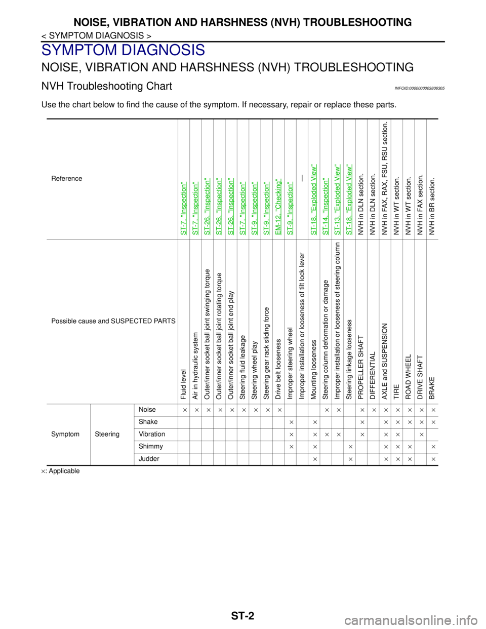
ST-2
< SYMPTOM DIAGNOSIS >
NOISE, VIBRATION AND HARSHNESS (NVH) TROUBLESHOOTING
SYMPTOM DIAGNOSIS
NOISE, VIBRATION AND HARSHNESS (NVH) TROUBLESHOOTING
NVH Troubleshooting ChartINFOID:0000000003806305
Use the chart below to find the cause of the symptom. If necessary, repair or replace these parts.
×: ApplicableReference
ST-7, "
Inspection
"
ST-7, "
Inspection
"
ST-26, "
Inspection
"
ST-26, "
Inspection
"
ST-26, "
Inspection
"
ST-7, "
Inspection
"
ST-9, "
Inspection
"
ST-9, "
Inspection
"
EM-12, "
Checking
"
ST-9, "
Inspection
"—
ST-18, "
Exploded View
"
ST-14, "
Inspection
"
ST-13, "
Exploded View
"
ST-18, "
Exploded View
"
NVH in DLN section.
NVH in DLN section.
NVH in FAX, RAX, FSU, RSU section.
NVH in WT section.
NVH in WT section.
NVH in FAX section.
NVH in BR section.
Possible cause and SUSPECTED PARTS
Fluid level
Air in hydraulic system
Outer/inner socket ball joint swinging torque
Outer/inner socket ball joint rotating torque
Outer/inner socket ball joint end play
Steering fluid leakage
Steering wheel play
Steering gear rack sliding force
Drive belt looseness
Improper steering wheel
Improper installation or looseness of tilt lock lever
Mounting looseness
Steering column deformation or damage
Improper installation or looseness of steering column
Steering linkage looseness
PROPELLER SHAFT
DIFFERENTIAL
AXLE and SUSPENSION
TIRE
ROAD WHEEL
DRIVE SHAFT
BRAKE
Symptom SteeringNoise××××××××× ×× ×××××××
Shake× × × ×××××
Vibration××××××××
Shimmy×× × ××××
Judder××××××