NISSAN TEANA 2008 Service Manual
TEANA 2008
NISSAN
NISSAN
https://www.carmanualsonline.info/img/5/57391/w960_57391-0.png
NISSAN TEANA 2008 Service Manual
Trending: wheel size, diagram, flat tire, rear entertainment, fuel cap release, fuse box diagram, radio
Page 4451 of 5121
STR-4
< BASIC INSPECTION >
DIAGNOSIS AND REPAIR WORKFLOW
NO >> Repair as needed.
9.CHECK MAGNETIC SWITCH OPERATION SOUND
Check that a magnetic switch operation sound can be heard when the ignition switch is set at the starting posi-
tion.
Does magnetic switch operation sound occur?
YES >> GO TO 10.
NO >> Replace magnetic switch.
10.PINION AND RING GEAR ENGAGEMENT CHECK
Check condition of pinion and ring gear mesh.
Is the inspection result normal?
YES >> GO TO 12.
NO >> GO TO 11.
11 .CHECK STARTER MOTOR UNIT
Check the following.
Adjust pinion movement. Refer to the following.
- VQ25DE models: STR-16, "
VQ25DE : Inspection"
- VQ35DE models: STR-22, "VQ35DE : Inspection"
Check pinion moving mechanism.
Check ring gear.
Are these inspection results normal?
YES >> INSPECTION END
NO >> Repair or replace, if necessary.
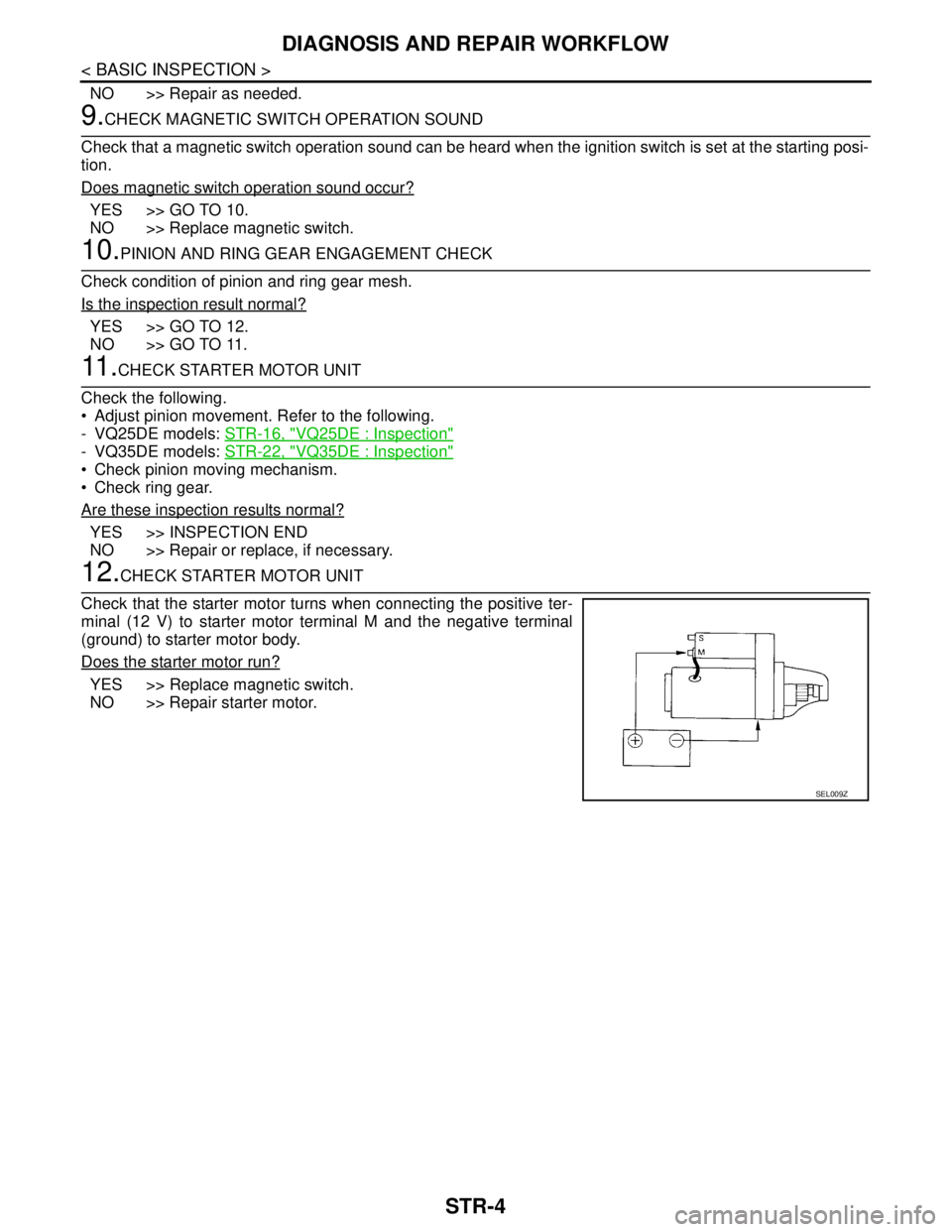
12.CHECK STARTER MOTOR UNIT
Check that the starter motor turns when connecting the positive ter-
minal (12 V) to starter motor terminal M and the negative terminal
(ground) to starter motor body.
Does the starter motor run?
YES >> Replace magnetic switch.
NO >> Repair starter motor.
SEL009Z
Page 4452 of 5121
STARTING SYSTEM
STR-5
< FUNCTION DIAGNOSIS >
C
D
E
F
G
H
I
J
K
L
MA
STR
N
P O
FUNCTION DIAGNOSIS
STARTING SYSTEM
VQ25DE
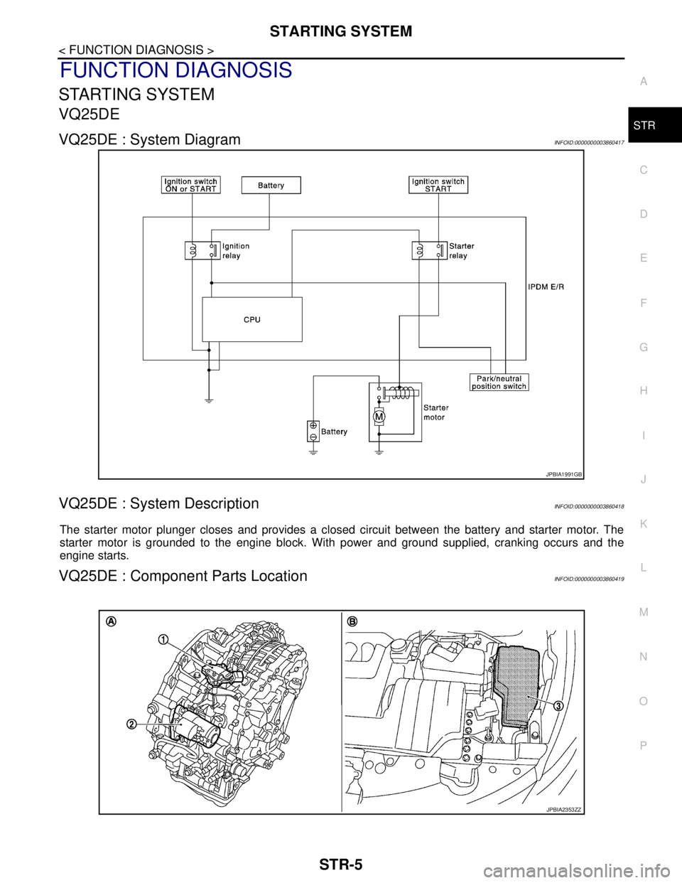
VQ25DE : System DiagramINFOID:0000000003860417
VQ25DE : System DescriptionINFOID:0000000003860418
The starter motor plunger closes and provides a closed circuit between the battery and starter motor. The
starter motor is grounded to the engine block. With power and ground supplied, cranking occurs and the
engine starts.
VQ25DE : Component Parts LocationINFOID:0000000003860419
JPBIA1991GB
JPBIA2353ZZ
Page 4453 of 5121
STR-6
< FUNCTION DIAGNOSIS >
STARTING SYSTEM
VQ25DE : Component Description
INFOID:0000000003860420
VQ35DE
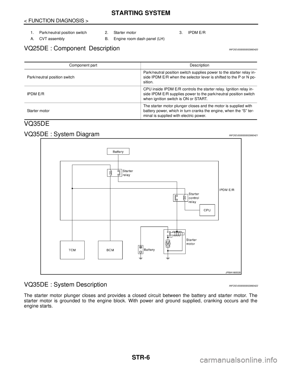
VQ35DE : System DiagramINFOID:0000000003860421
VQ35DE : System DescriptionINFOID:0000000003860422
The starter motor plunger closes and provides a closed circuit between the battery and starter motor. The
starter motor is grounded to the engine block. With power and ground supplied, cranking occurs and the
engine starts.
1. Park/neutral position switch 2. Starter motor 3. IPDM E/R
A. CVT assembly B. Engine room dash panel (LH)
Component part Description
Park/neutral position switchPark/neutral position switch supplies power to the starter relay in-
side IPDM E/R when the selector lever is shifted to the P or N po-
sition.
IPDM E/RCPU inside IPDM E/R controls the starter relay. Ignition relay in-
side IPDM E/R supplies power to the park/neutral position switch
when ignition switch is ON or START.
Starter motorThe starter motor plunger closes and the motor is supplied with
battery power, which in turn cranks the engine, when the “S” ter-
minal is supplied with electric power.
JPBIA1665GB
Page 4454 of 5121
STARTING SYSTEM
STR-7
< FUNCTION DIAGNOSIS >
C
D
E
F
G
H
I
J
K
L
MA
STR
N
P O
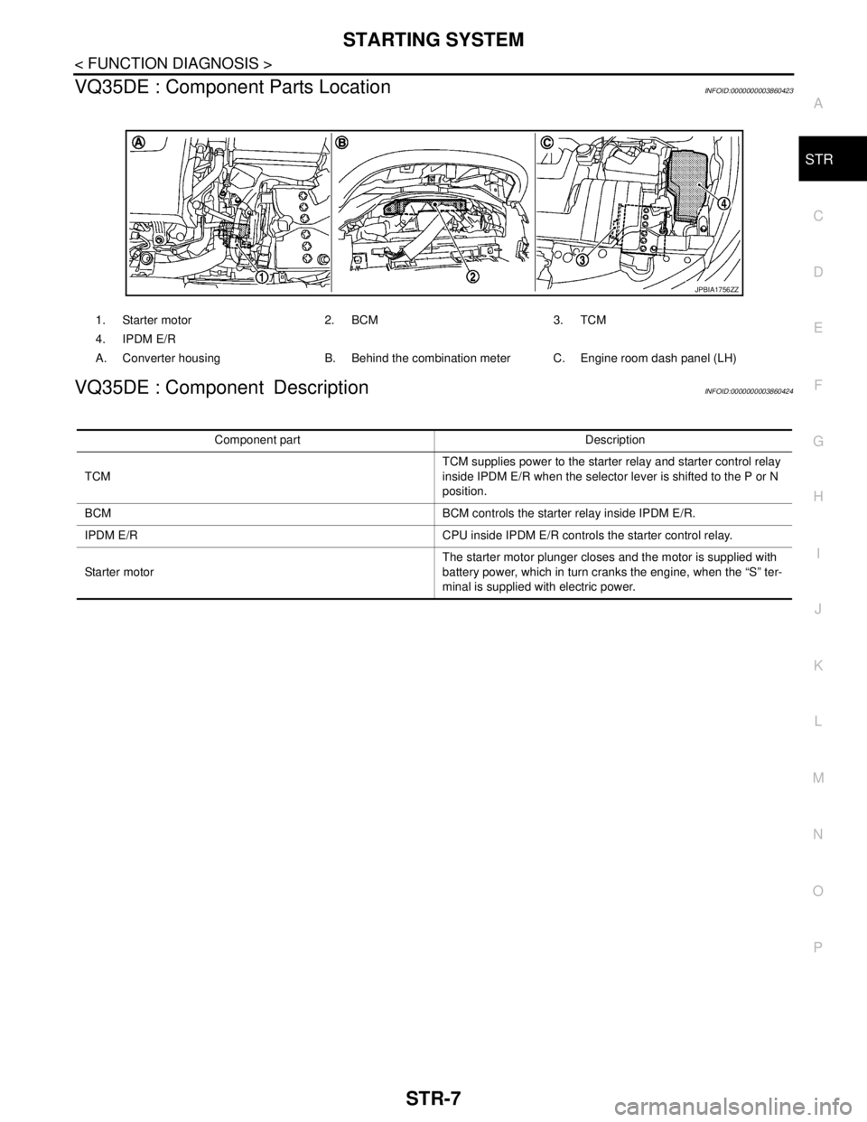
VQ35DE : Component Parts LocationINFOID:0000000003860423
VQ35DE : Component DescriptionINFOID:0000000003860424
1. Starter motor 2. BCM 3. TCM
4. IPDM E/R
A. Converter housing B. Behind the combination meter C. Engine room dash panel (LH)
JPBIA1756ZZ
Component part Description
TCMTCM supplies power to the starter relay and starter control relay
inside IPDM E/R when the selector lever is shifted to the P or N
position.
BCM BCM controls the starter relay inside IPDM E/R.
IPDM E/R CPU inside IPDM E/R controls the starter control relay.
Starter motorThe starter motor plunger closes and the motor is supplied with
battery power, which in turn cranks the engine, when the “S” ter-
minal is supplied with electric power.
Page 4455 of 5121
STR-8
< COMPONENT DIAGNOSIS >
B TERMINAL CIRCUIT
COMPONENT DIAGNOSIS
B TERMINAL CIRCUIT
DescriptionINFOID:0000000003860425
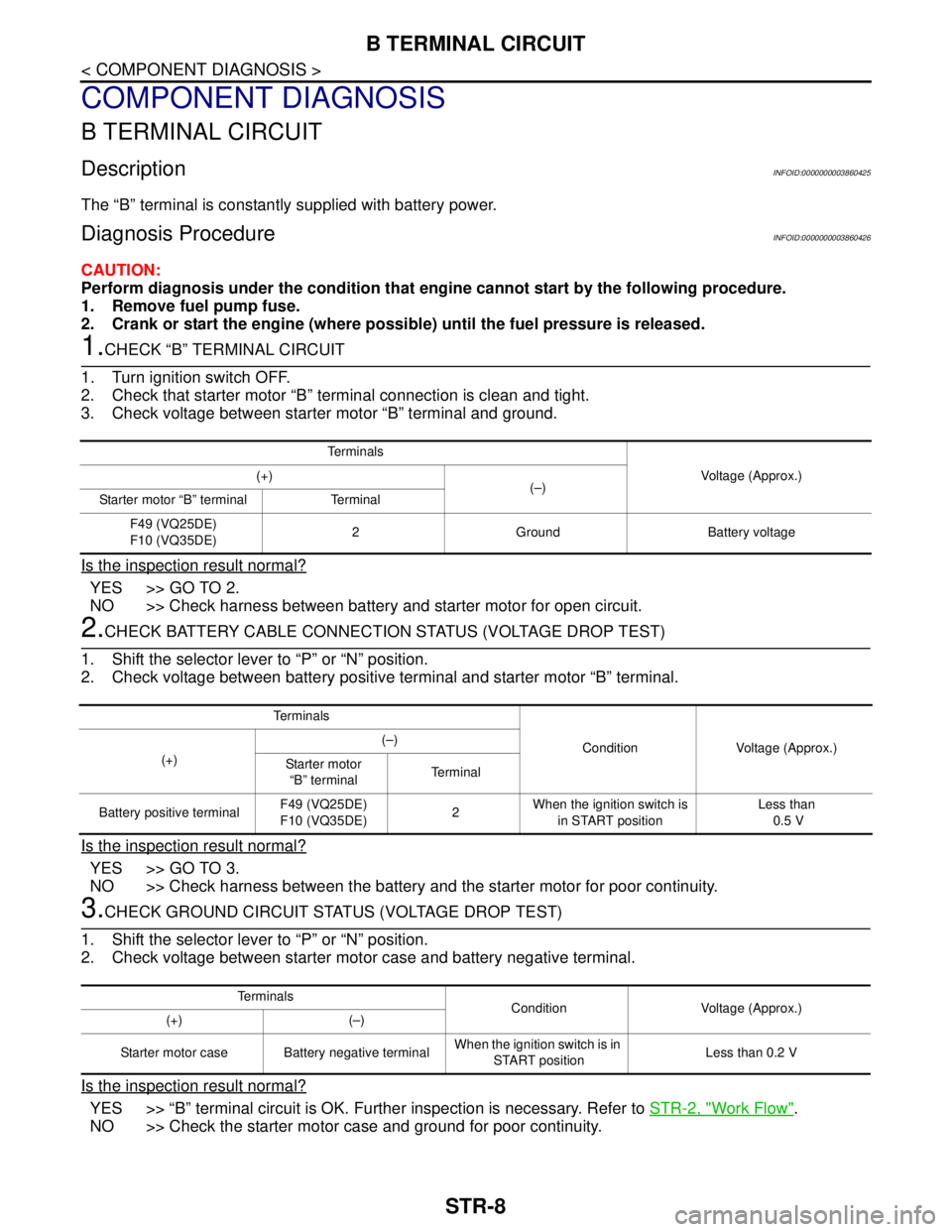
The “B” terminal is constantly supplied with battery power.
Diagnosis ProcedureINFOID:0000000003860426
CAUTION:
Perform diagnosis under the condition that engine cannot start by the following procedure.
1. Remove fuel pump fuse.
2. Crank or start the engine (where possible) until the fuel pressure is released.
1.CHECK “B” TERMINAL CIRCUIT
1. Turn ignition switch OFF.
2. Check that starter motor “B” terminal connection is clean and tight.
3. Check voltage between starter motor “B” terminal and ground.
Is the inspection result normal?
YES >> GO TO 2.
NO >> Check harness between battery and starter motor for open circuit.
2.CHECK BATTERY CABLE CONNECTION STATUS (VOLTAGE DROP TEST)
1. Shift the selector lever to “P” or “N” position.
2. Check voltage between battery positive terminal and starter motor “B” terminal.
Is the inspection result normal?
YES >> GO TO 3.
NO >> Check harness between the battery and the starter motor for poor continuity.
3.CHECK GROUND CIRCUIT STATUS (VOLTAGE DROP TEST)
1. Shift the selector lever to “P” or “N” position.
2. Check voltage between starter motor case and battery negative terminal.
Is the inspection result normal?
YES >> “B” terminal circuit is OK. Further inspection is necessary. Refer to STR-2, "Work Flow".
NO >> Check the starter motor case and ground for poor continuity.
Te r m i n a l s
Voltage (Approx.) (+)
(–)
Starter motor “B” terminal Terminal
F49 (VQ25DE)
F10 (VQ35DE)2 Ground Battery voltage
Te r m i n a l s
Condition Voltage (Approx.)
(+)(–)
Starter motor
“B” terminalTerminal
Battery positive terminalF49 (VQ25DE)
F10 (VQ35DE)2 When the ignition switch is
in START positionLess than
0.5 V
Te r m i n a l s
Condition Voltage (Approx.)
(+) (–)
Starter motor case Battery negative terminalWhen the ignition switch is in
START positionLess than 0.2 V
Page 4456 of 5121
S TERMINAL CIRCUIT
STR-9
< COMPONENT DIAGNOSIS >
C
D
E
F
G
H
I
J
K
L
MA
STR
N
P O
S TERMINAL CIRCUIT
DescriptionINFOID:0000000003860427
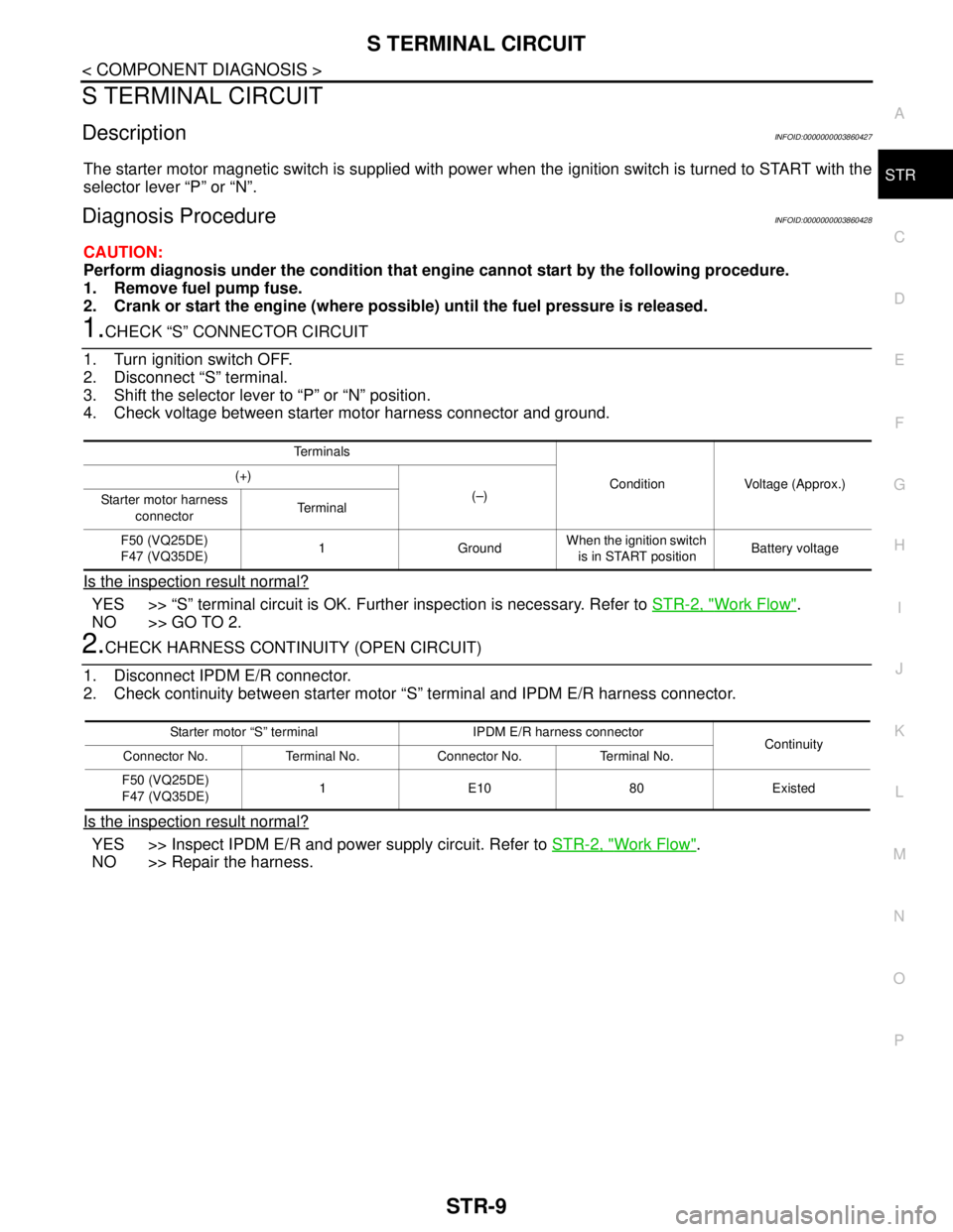
The starter motor magnetic switch is supplied with power when the ignition switch is turned to START with the
selector lever “P” or “N”.
Diagnosis ProcedureINFOID:0000000003860428
CAUTION:
Perform diagnosis under the condition that engine cannot start by the following procedure.
1. Remove fuel pump fuse.
2. Crank or start the engine (where possible) until the fuel pressure is released.
1.CHECK “S” CONNECTOR CIRCUIT
1. Turn ignition switch OFF.
2. Disconnect “S” terminal.
3. Shift the selector lever to “P” or “N” position.
4. Check voltage between starter motor harness connector and ground.
Is the inspection result normal?
YES >> “S” terminal circuit is OK. Further inspection is necessary. Refer to STR-2, "Work Flow".
NO >> GO TO 2.
2.CHECK HARNESS CONTINUITY (OPEN CIRCUIT)
1. Disconnect IPDM E/R connector.
2. Check continuity between starter motor “S” terminal and IPDM E/R harness connector.
Is the inspection result normal?
YES >> Inspect IPDM E/R and power supply circuit. Refer to STR-2, "Work Flow".
NO >> Repair the harness.
Te r m i n a l s
Condition Voltage (Approx.) (+)
(–)
Starter motor harness
connectorTe r m i n a l
F50 (VQ25DE)
F47 (VQ35DE)1 GroundWhen the ignition switch
is in START positionBattery voltage
Starter motor “S” terminal IPDM E/R harness connector
Continuity
Connector No. Terminal No. Connector No. Terminal No.
F50 (VQ25DE)
F47 (VQ35DE)1E1080Existed
Page 4457 of 5121
STR-10
< COMPONENT DIAGNOSIS >
STARTING SYSTEM
STARTING SYSTEM
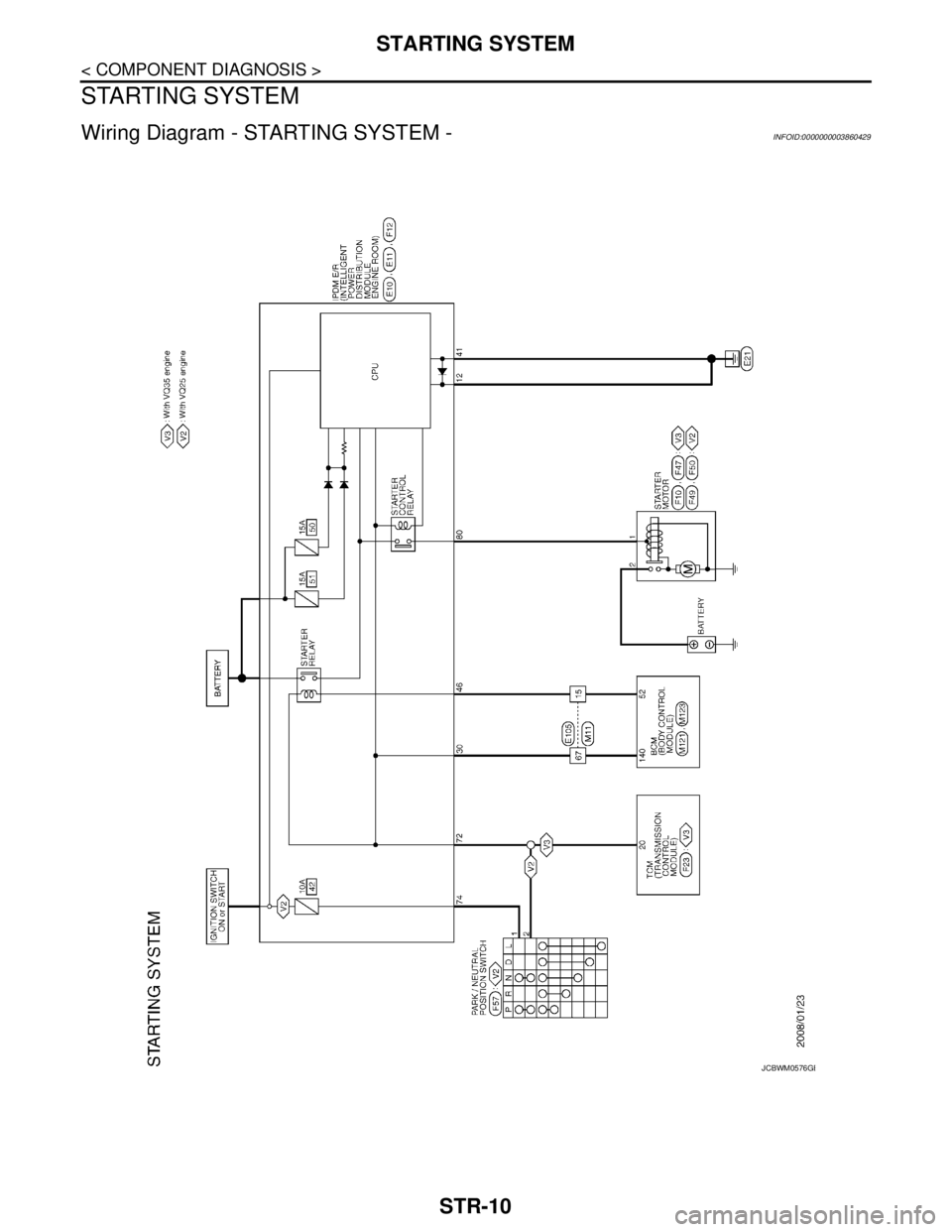
Wiring Diagram - STARTING SYSTEM -INFOID:0000000003860429
JCBWM0576GB
Page 4458 of 5121
STARTING SYSTEM
STR-11
< COMPONENT DIAGNOSIS >
C
D
E
F
G
H
I
J
K
L
MA
STR
N
P O
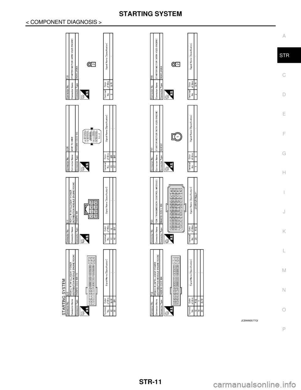
JCBWM0577GB
Page 4459 of 5121
STR-12
< COMPONENT DIAGNOSIS >
STARTING SYSTEM
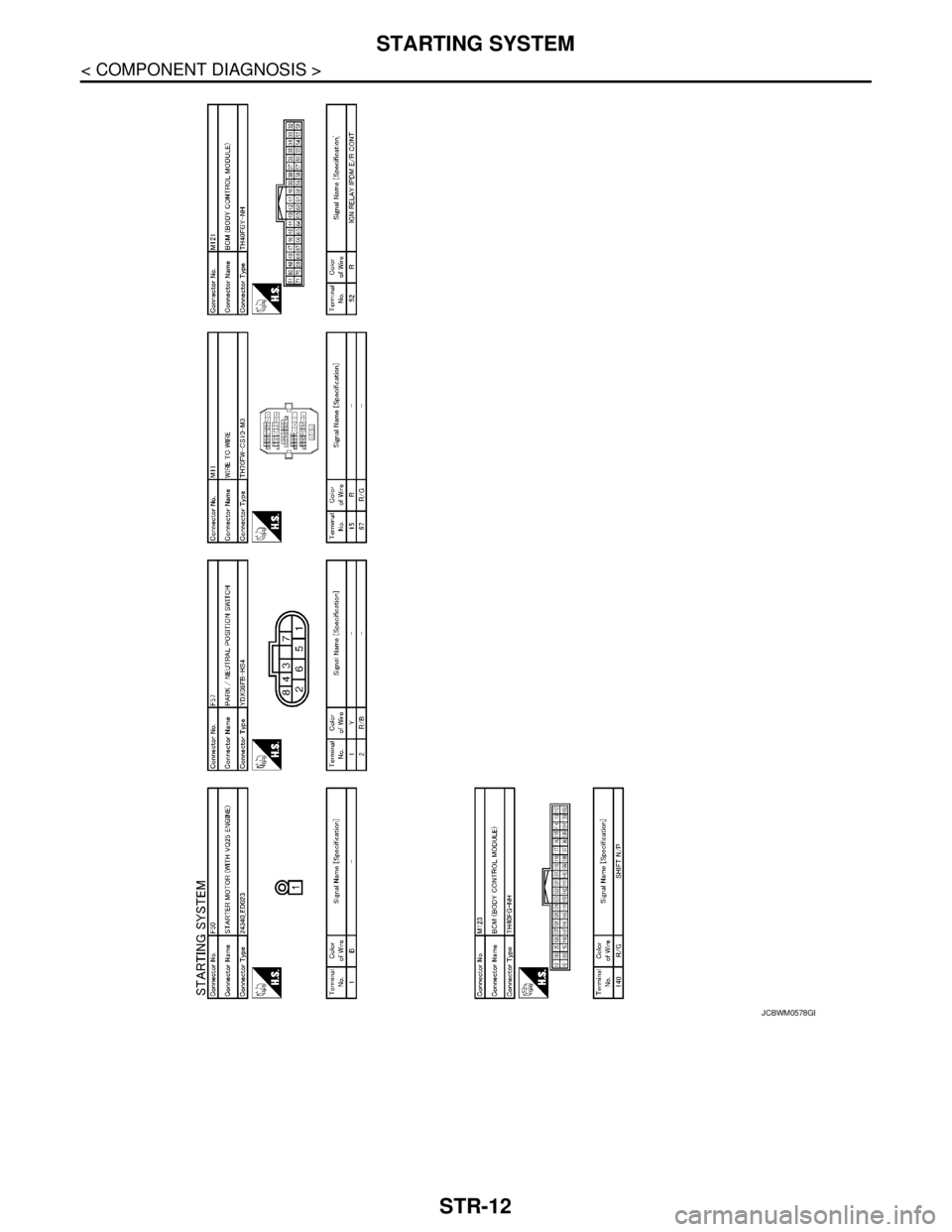
JCBWM0578GB
Page 4460 of 5121
STARTING SYSTEM
STR-13
< SYMPTOM DIAGNOSIS >
C
D
E
F
G
H
I
J
K
L
MA
STR
N
P O
SYMPTOM DIAGNOSIS
STARTING SYSTEM
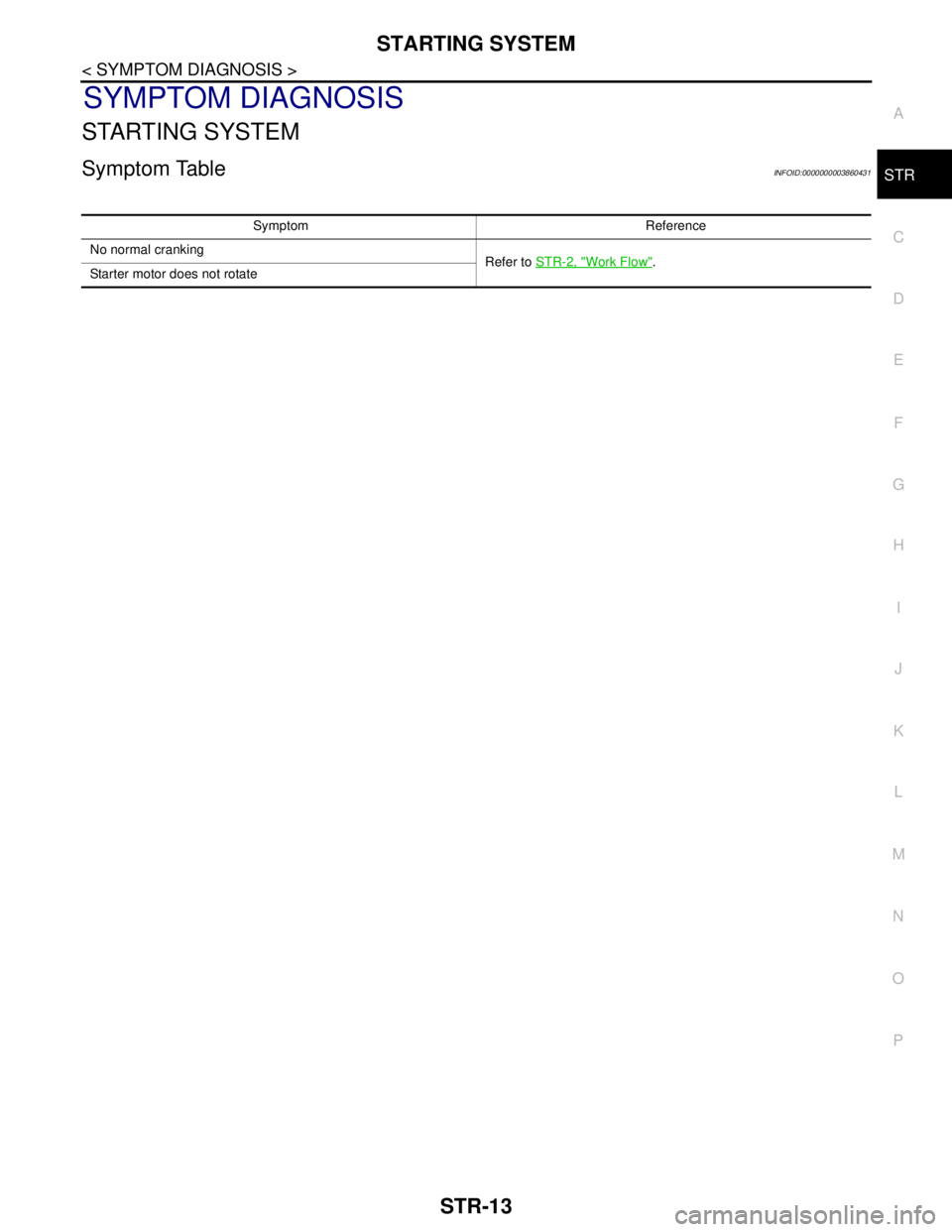
Symptom TableINFOID:0000000003860431
Symptom Reference
No normal cranking
Refer to STR-2, "
Work Flow".
Starter motor does not rotate
Trending: width, gas tank size, catalytic converter, open gas tank, spare wheel, tire size, camera

