NISSAN TEANA 2014 Service Manual
Manufacturer: NISSAN, Model Year: 2014, Model line: TEANA, Model: NISSAN TEANA 2014Pages: 4801, PDF Size: 51.2 MB
Page 2941 of 4801
INSTRUMENT PANEL ASSEMBLYIP-15
< REMOVAL AND INSTALLATION >
C
D E
F
G H
I
K L
M A
B
IP
N
O P
Removal and Installation INFOID:0000000009461379
CAUTION:
• Be careful not to scratch instrument panel pad and other parts.
• Whenever a suitable tool is used, always wrap a cloth around the end of the tool to protect compo-
nents from damage.
• Before servicing, turn ignition swit ch OFF, disconnect both battery terminals and wait at least three
minutes.
REMOVAL
1. Disconnect the negative and positive bat tery terminals, then wait at least three minutes. Refer to PG-73,
"Removal and Installation (Battery)"
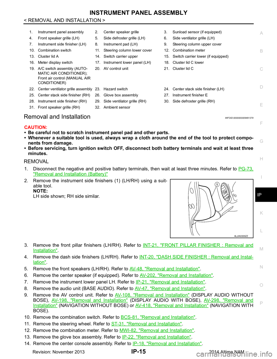
2. Remove the instrument side finishers (1) (LH/RH) using a suit-
able tool.
NOTE:
LH side shown; RH side similar.
3. Remove the front pillar finishers (LH/RH). Refer to INT-21, "FRONT PILLAR FINISHER : Removal and
Installation".
4. Remove the dash side finishers (LH/RH). Refer to INT-20, "DASH SIDE FINISHER : Removal and Instal-
lation".
5. Remove the front speakers (LH/RH). Refer to AV-48, "Removal and Installation"
.
6. Remove the center speaker (if equipped). Refer to AV-202, "Removal and Installation"
.
7. Remove the instrument lower panel LH. Refer to IP-21, "Removal and Installation"
.
8. Remove the audio unit (BASE AUDIO). Refer to AV-47, "Removal and Installation"
.
9. Remove the AV control unit. Refer to AV-108, "Removal and Installation"
(DISPLAY AUDIO WITHOUT
BOSE), AV-198, "Removal and Installation"
(DISPLAY AUDIO WITH BOSE), AV-298, "Removal and
Installation" (NAVIGATION WITHOUT BOSE) or AV-418, "Removal and Installation" ( N AV I G AT I O N W I T H
BOSE).
10. Remove the combination switch. Refer to BCS-81, "Removal and Installation"
.
11. Remove the steering wheel. Refer to ST-31, "Removal and Installation"
.
12. Remove the combination meter. Refer to MWI-82, "Removal and Installation"
.
13. Remove the glove box assembly. Refer to IP-22, "Removal and Installation"
.
14. Remove the center console assembly. Refer to IP-18, "Removal and Installation"
.
1. Instrument panel assembly 2. Center speaker grille 3. Sunload sensor (if equipped)
4. Front speaker grille (LH) 5. Side defroster grille (LH) 6. Side ventilator grille (LH)
7. Instrument side finisher (LH) 8. Instrument pad (LH) 9. Steering column upper cover
10. Combination switch 11. Steering column lower cover 12. Combination meter
13. Cluster lid A 14. Switch carrier upper 15. Switch carrier lower (if equipped)
16. Meter display switch 17. Instrument lower panel (LH) 18. Cluster lid C lower
19. A/C switch assembly (AUTO- MATIC AIR CONDITIONER);
Front air control (MANUAL AIR
CONDITIONER) 20. AV control unit 21. Cluster lid C
22. Center ventilator grille assembly 23. Hazard switch 24. Center stack side finisher (LH)
25. Center stack side finisher (RH) 26. Glove box assembly 27. Instrument finisher E
28. Instrument side finisher (RH) 29. Side ventilator grille (RH) 30. Side defroster grille (RH)
31. Front speaker grille (RH) 32. Ambient sensor
ALJIA0335ZZ
Revision: November 20132014 Altima NAM
Page 2942 of 4801
IP-16
< REMOVAL AND INSTALLATION >
INSTRUMENT PANEL ASSEMBLY
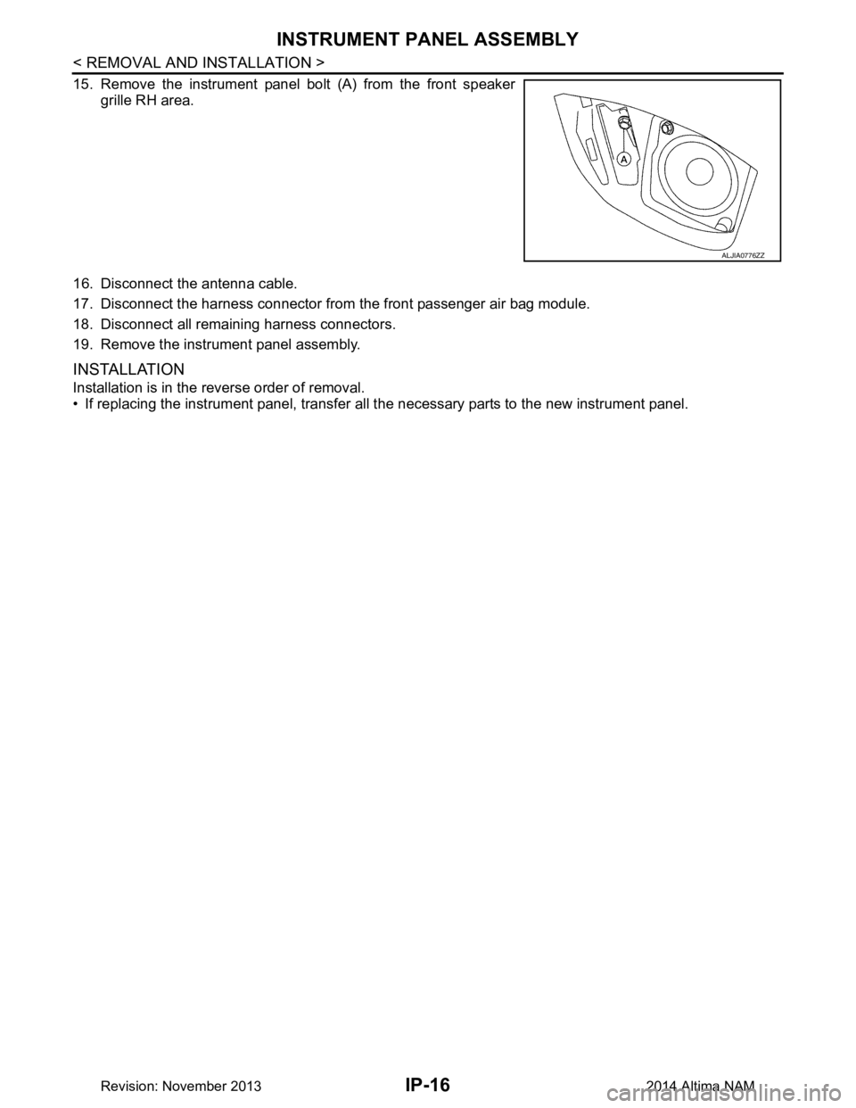
15. Remove the instrument panel bolt (A) from the front speaker
grille RH area.
16. Disconnect the antenna cable.
17. Disconnect the harness connector from the front passenger air bag module.
18. Disconnect all remaining harness connectors.
19. Remove the instrument panel assembly.
INSTALLATION
Installation is in the reverse order of removal.
• If replacing the instrument panel, transfer all t he necessary parts to the new instrument panel.
ALJIA0776ZZ
Revision: November 20132014 Altima NAM
Page 2943 of 4801
STEERING COLUMN COVERSIP-17
< REMOVAL AND INSTALLATION >
C
D E
F
G H
I
K L
M A
B
IP
N
O P
STEERING COLUMN COVERS
Removal and InstallationINFOID:0000000009461380
REMOVAL
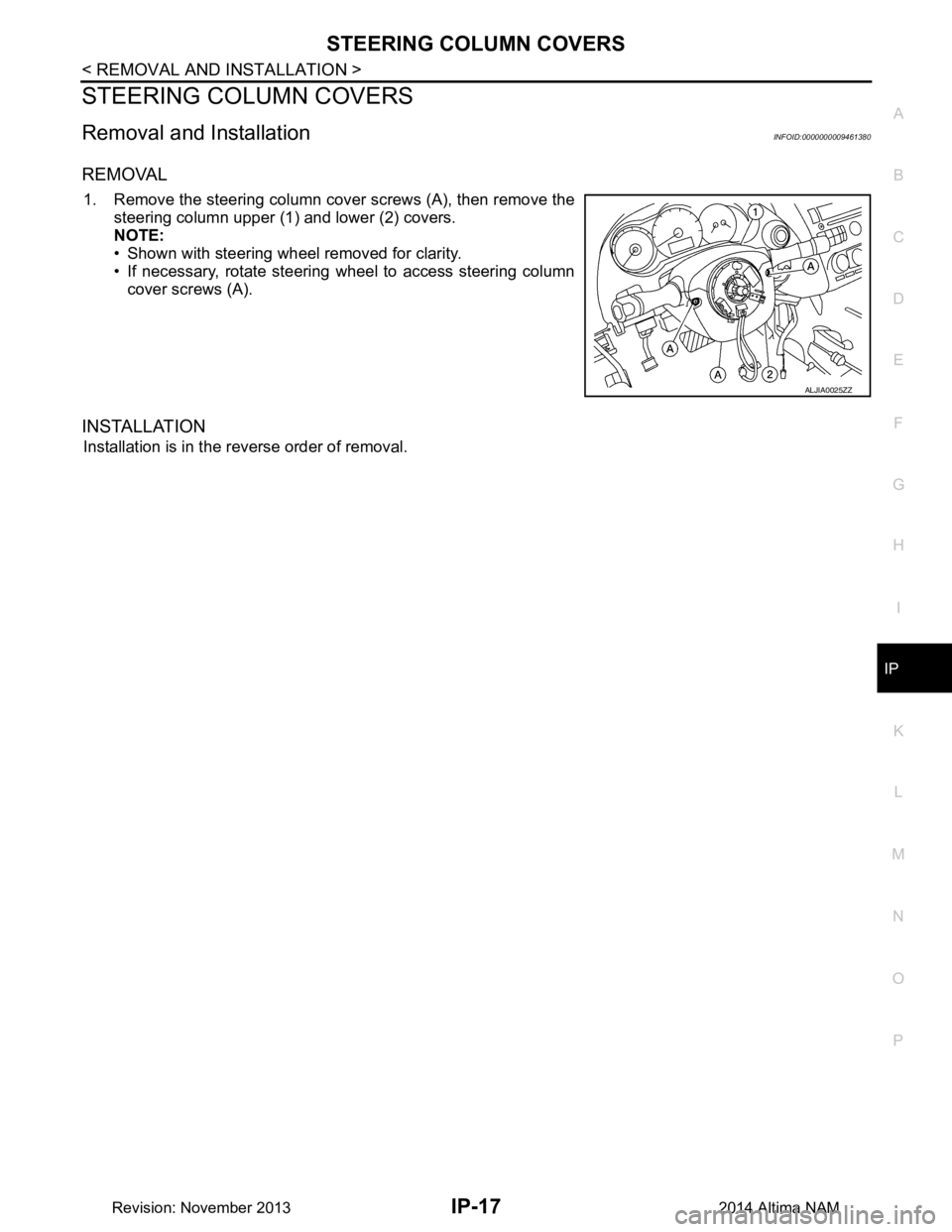
1. Remove the steering column cover screws (A), then remove the steering column upper (1) and lower (2) covers.
NOTE:
• Shown with steering wheel removed for clarity.
• If necessary, rotate steering wheel to access steering column
cover screws (A).
INSTALLATION
Installation is in the reverse order of removal.
ALJIA0025ZZ
Revision: November 20132014 Altima NAM
Page 2944 of 4801
IP-18
< REMOVAL AND INSTALLATION >
CENTER CONSOLE ASSEMBLY
CENTER CONSOLE ASSEMBLY
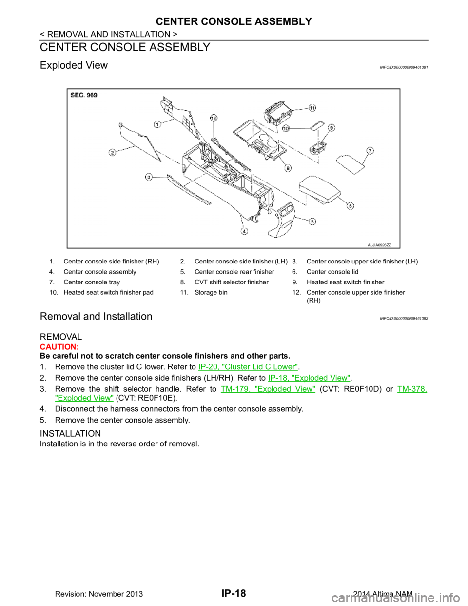
Exploded ViewINFOID:0000000009461381
Removal and InstallationINFOID:0000000009461382
REMOVAL
CAUTION:
Be careful not to scratch center console finishers and other parts.
1. Remove the cluster lid C lower. Refer to IP-20, "Cluster Lid C Lower"
.
2. Remove the center console side finishers (LH/RH). Refer to IP-18, "Exploded View"
.
3. Remove the shift selector handle. Refer to TM-179, "Exploded View"
(CVT: RE0F10D) or TM-378,
"Exploded View" (CVT: RE0F10E).
4. Disconnect the harness connectors from the center console assembly.
5. Remove the center console assembly.
INSTALLATION
Installation is in the reverse order of removal.
1. Center console side finisher (RH) 2. Center console side finisher (LH) 3. Center console upper side finisher (LH)
4. Center console assembly 5. Center console rear finisher 6. Center console lid
7. Center console tray 8. CVT shift selector finisher 9. Heated seat switch finisher
10. Heated seat switch finisher pad 11. Storage bin 12. Center console upper side finisher (RH)
ALJIA0926ZZ
Revision: November 20132014 Altima NAM
Page 2945 of 4801
CLUSTER LID AIP-19
< REMOVAL AND INSTALLATION >
C
D E
F
G H
I
K L
M A
B
IP
N
O P
CLUSTER LID A
Removal and InstallationINFOID:0000000009461383
REMOVAL
1. Remove the instrument lower panel LH. Refer to IP-21, "Removal and Installation".
2. Remove the steering column upper cover. Refer to IP-17, "Removal and Installation"
.
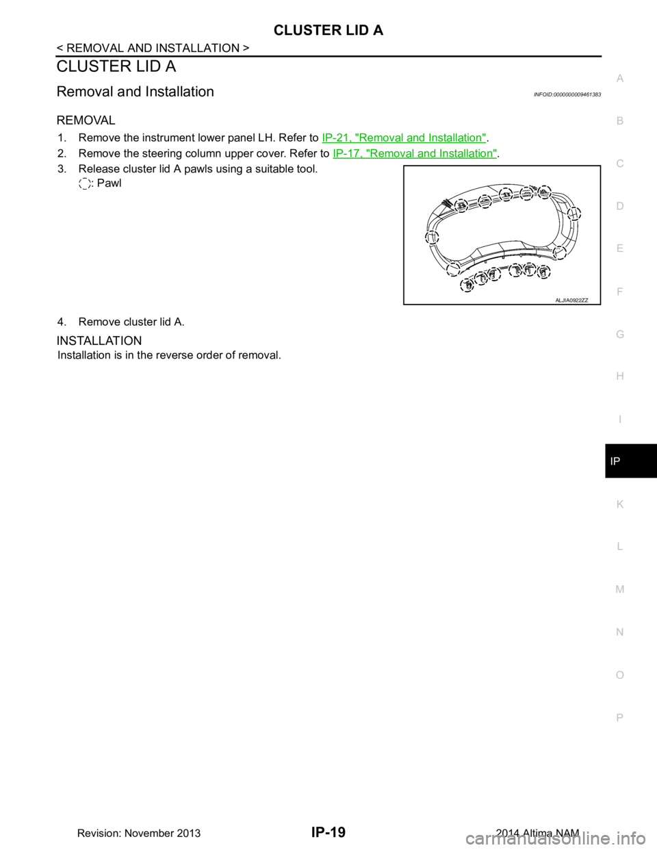
3. Release cluster lid A pawls using a suitable tool. : Pawl
4. Remove cluster lid A.
INSTALLATION
Installation is in the reverse order of removal.
ALJIA0922ZZ
Revision: November 20132014 Altima NAM
Page 2946 of 4801
IP-20
< REMOVAL AND INSTALLATION >
CLUSTER LID C
CLUSTER LID C
Cluster Lid CINFOID:0000000009461384
REMOVAL
1. Remove the center stack side finishers (LH/RH). Refer to IP-14, "Exploded View".
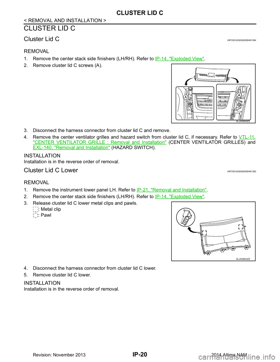
2. Remove cluster lid C screws (A).
3. Disconnect the harness connector from cluster lid C and remove.
4. Remove the center ventilator grilles and hazard swit ch from cluster lid C, if necessary. Refer to VTL-11,
"CENTER VENTILATOR GRILLE : Removal and Installation" (CENTER VENTILATOR GRILLES) and
EXL-140, "Removal and Installation"
(HAZARD SWITCH).
INSTALLATION
Installation is in the reverse order of removal.
Cluster Lid C LowerINFOID:0000000009461385
REMOVAL
1. Remove the instrument lower panel LH. Refer to IP-21, "Removal and Installation".
2. Remove the center stack side finishers (LH/RH). Refer to IP-14, "Exploded View"
.
3. Release cluster lid C lower metal clips and pawls. : Metal clip
: Pawl
4. Disconnect the harness connector from cluster lid C lower.
5. Remove cluster lid C lower.
INSTALLATION
Installation is in the reverse order of removal.
ALJIA0923ZZ
ALJIA0924ZZ
Revision: November 20132014 Altima NAM
Page 2947 of 4801
INSTRUMENT LOWER PANEL LHIP-21
< REMOVAL AND INSTALLATION >
C
D E
F
G H
I
K L
M A
B
IP
N
O P
INSTRUMENT LOWER PANEL LH
Removal and InstallationINFOID:0000000009461386
REMOVAL
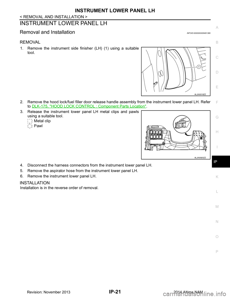
1. Remove the instrument side finisher (LH) (1) using a suitable tool.
2. Remove the hood lock/fuel filler door release handle assembly from the instrument lower panel LH. Refer to DLK-175, "HOOD LOCK CONTRO L : Component Parts Location"
.
3. Release the instrument lower panel LH metal clips and pawls using a suitable tool.
: Metal clip
: Pawl
4. Disconnect the harness connectors from the instrument lower panel LH.
5. Remove the aspirator hose from the instrument lower panel LH.
6. Remove the instrument lower panel LH.
INSTALLATION
Installation is in the reverse order of removal.
ALJIA0018ZZ
ALJIA0925ZZ
Revision: November 20132014 Altima NAM
Page 2948 of 4801
IP-22
< REMOVAL AND INSTALLATION >
GLOVE BOX ASSEMBLY
GLOVE BOX ASSEMBLY
Removal and InstallationINFOID:0000000009461387
REMOVAL
1. Remove the instrument side finisher RH using a suitable tool.
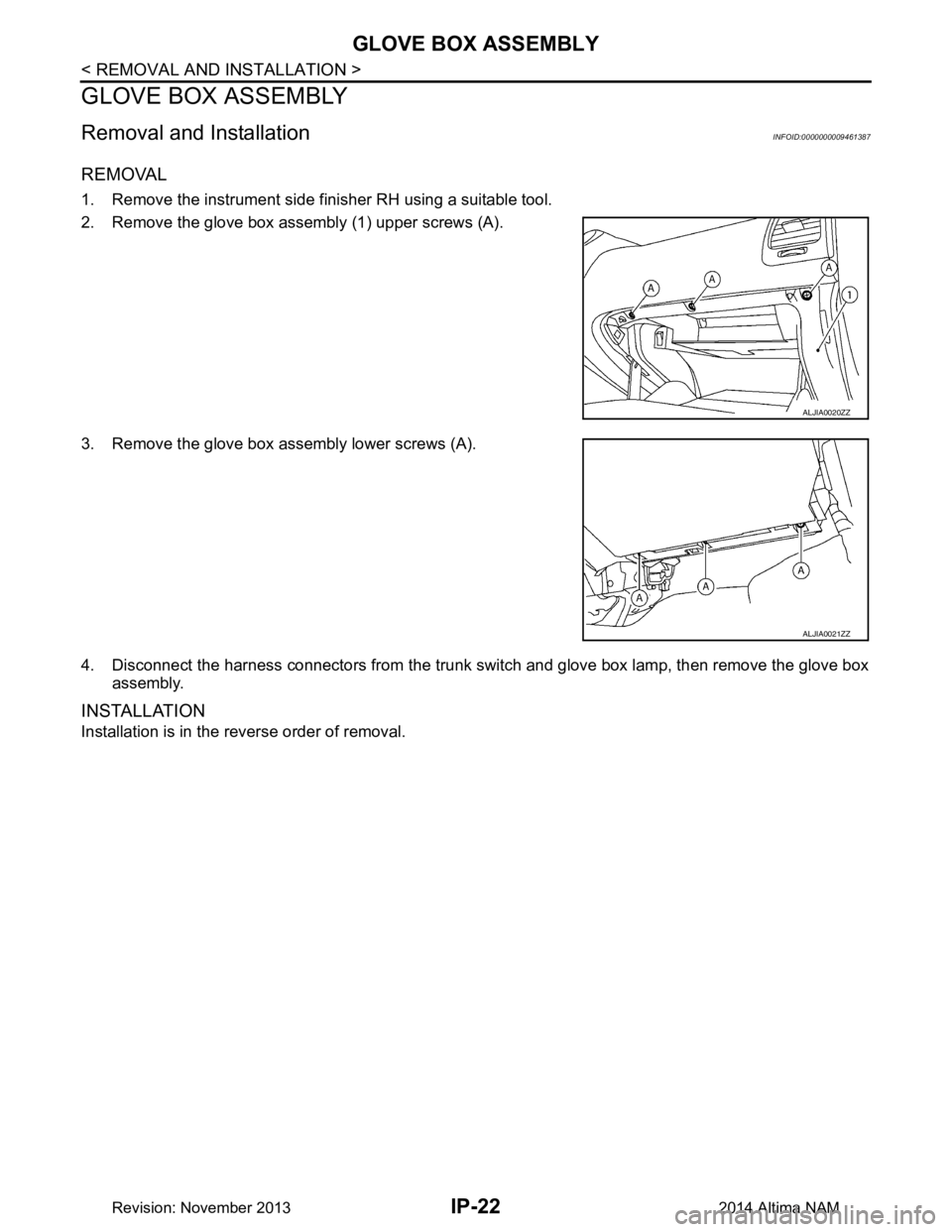
2. Remove the glove box assembly (1) upper screws (A).
3. Remove the glove box assembly lower screws (A).
4. Disconnect the harness connectors from the trunk switch and glove box lamp, then remove the glove box assembly.
INSTALLATION
Installation is in the reverse order of removal.
ALJIA0020ZZ
ALJIA0021ZZ
Revision: November 20132014 Altima NAM
Page 2949 of 4801
CENTER CONSOLE ASSEMBLYIP-23
< UNIT DISASSEMBLY AND ASSEMBLY >
C
D E
F
G H
I
K L
M A
B
IP
N
O P
UNIT DISASSEMBLY AND ASSEMBLY
CENTER CONSOLE ASSEMBLY
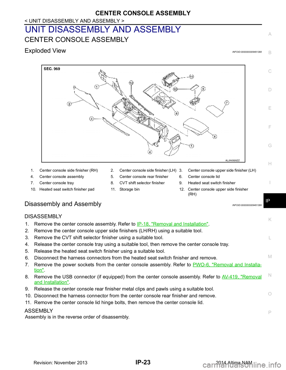
Exploded ViewINFOID:0000000009461388
Disassembly and AssemblyINFOID:0000000009461389
DISASSEMBLY
1. Remove the center console assembly. Refer to IP-18, "Removal and Installation".
2. Remove the center console upper side finishers (LH/RH) using a suitable tool.
3. Remove the CVT shift selector finisher using a suitable tool.
4. Release the center console tray using a suit able tool, then remove the center console tray.
5. Release the heated seat switch finisher using a suitable tool.
6. Disconnect the harness connectors from the heated seat switch finisher and remove.
7. Remove the power sockets from the center console assembly. Refer to PWO-6, "Removal and Installa-
tion".
8. Remove the USB connector (if equipped) from the center console assembly. Refer to AV-419, "Removal
and Installation".
9. Release the center console rear finisher metal clips and pawls using a suitable tool.
10. Disconnect the harness connector from the c enter console rear finisher and remove.
11. Remove the center console lid hinge bol ts, then remove the center console lid.
ASSEMBLY
Assembly is in the reverse order of disassembly.
1. Center console side finisher (RH) 2. Center console side finisher (LH) 3. Center console upper side finisher (LH)
4. Center console assembly 5. Center console rear finisher 6. Center console lid
7. Center console tray 8. CVT shift selector finisher 9. Heated seat switch finisher
10. Heated seat switch finisher pad 11. Storage bin 12. Center console upper side finisher (RH)
ALJIA0926ZZ
Revision: November 20132014 Altima NAM
Page 2950 of 4801
LAN
LAN-1
ELECTRICAL & POWER CONTROL
C
D E
F
G H
I
J
K L
B
SECTION LAN
A
O P
N
CONTENTS
LAN SYSTEM
CAN FUNDAMENTAL
HOW TO USE THIS MANU AL ......................
7
HOW TO USE THIS SECTION ....................... .....7
Information .......................................................... ......7
PRECAUTION ...............................................8
PRECAUTIONS .............................................. .....8
Precautions for Trouble Diagnosis ...................... ......8
Precautions for Harness Repair ................................8
SYSTEM DESCRIPTION . .............................9
SYSTEM ......................................................... .....9
CAN COMMUNICATION SYSTEM .............................9
CAN COMMUNICATION SYSTEM : System De-
scription ............................................................... ......
9
DIAG ON CAN ....................................................... ......9
DIAG ON CAN : System Description ........................9
TROUBLE DIAGNOSIS .....................................11
Component Description ....................................... ....11
Condition of Error Detection ....................................11
Symptom When Error Occurs in CAN Communi-
cation System ...................................................... ....
12
CAN Diagnosis with CONSULT ..............................14
Self-Diagnosis .........................................................15
CAN Diagnostic Support Monitor ............................15
How to Use CAN Communication Signal Chart ......17
BASIC INSPECTION ...................................18
DIAGNOSIS AND REPAIR WORKFLOW ..... ....18
Trouble Diagnosis Flow Chart ............................. ....18
Trouble Diagnosis Procedure ..................................18
CAN
HOW TO USE THIS MANU AL .....................
23
HOW TO USE THIS SECTION .........................23
Information ........................................................... ....23
Abbreviation List ......................................................23
PRECAUTION ..............................................24
PRECAUTIONS .................................................24
Precaution for Supplemental Restraint System
(SRS) "AIR BAG" and "SEAT BELT PRE-TEN-
SIONER" ............................................................. ....
24
Precautions for Trouble Diagnosis ..........................24
Precautions for Harness Repair ..............................24
SYSTEM DESCRIPTION .............................26
COMPONENT PARTS ......................................26
Component Parts Location .................................. ....26
SYSTEM ............................................................27
CAN COMMUNICATION SYSTEM ........................ ....27
CAN COMMUNICATION SYSTEM : System De-
scription ............................................................... ....
27
CAN COMMUNICATION SYSTEM : CAN Com-
munication Control Circuit ................................... ....
30
CAN COMMUNICATION SYSTEM : CAN System
Specification Chart .............................................. ....
31
CAN COMMUNICATION SYSTEM : CAN Com-
munication Signal Chart ...................................... ....
32
WIRING DIAGRAM ......................................36
CAN SYSTEM .. ................................ .................36
Wiring Diagram .................................................... ....36
BASIC INSPECTION ...................................42
DIAGNOSIS AND REPAIR WORKFLOW ........42
Interview Sheet .................................................... ....42
DTC/CIRCUIT DIAGNOSIS .........................43
MALFUNCTION AREA CHART ........................43
Revision: November 20132014 Altima NAMRevision: November 20132014 Altima NAM