NISSAN TERRANO 2002 Service Repair Manual
Manufacturer: NISSAN, Model Year: 2002, Model line: TERRANO, Model: NISSAN TERRANO 2002Pages: 1767, PDF Size: 41.51 MB
Page 1351 of 1767
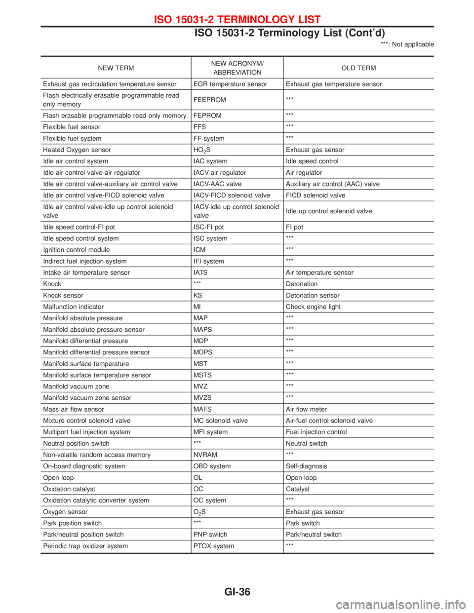
***: Not applicable
NEW TERMNEW ACRONYM/
ABBREVIATIONOLD TERM
Exhaust gas recirculation temperature sensor EGR temperature sensor Exhaust gas temperature sensor
Flash electrically erasable programmable read
only memoryFEEPROM ***
Flash erasable programmable read only memory FEPROM ***
Flexible fuel sensor FFS ***
Flexible fuel system FF system ***
Heated Oxygen sensor HO
2S Exhaust gas sensor
Idle air control system IAC system Idle speed control
Idle air control valve-air regulator IACV-air regulator Air regulator
Idle air control valve-auxiliary air control valve IACV-AAC valve Auxiliary air control (AAC) valve
Idle air control valve-FICD solenoid valve IACV-FICD solenoid valve FICD solenoid valve
Idle air control valve-idle up control solenoid
valveIACV-idle up control solenoid
valveIdle up control solenoid valve
Idle speed control-FI pot ISC-FI pot FI pot
Idle speed control system ISC system ***
Ignition control module ICM ***
Indirect fuel injection system IFI system ***
Intake air temperature sensor IATS Air temperature sensor
Knock *** Detonation
Knock sensor KS Detonation sensor
Malfunction indicator MI Check engine light
Manifold absolute pressure MAP ***
Manifold absolute pressure sensor MAPS ***
Manifold differential pressure MDP ***
Manifold differential pressure sensor MDPS ***
Manifold surface temperature MST ***
Manifold surface temperature sensor MSTS ***
Manifold vacuum zone MVZ ***
Manifold vacuum zone sensor MVZS ***
Mass air flow sensor MAFS Air flow meter
Mixture control solenoid valve MC solenoid valve Air-fuel control solenoid valve
Multiport fuel injection system MFI system Fuel injection control
Neutral position switch *** Neutral switch
Non-volatile random access memory NVRAM ***
On-board diagnostic system OBD system Self-diagnosis
Open loop OL Open loop
Oxidation catalyst OC Catalyst
Oxidation catalytic converter system OC system ***
Oxygen sensor O
2S Exhaust gas sensor
Park position switch *** Park switch
Park/neutral position switch PNP switch Park/neutral switch
Periodic trap oxidizer system PTOX system ***
ISO 15031-2 TERMINOLOGY LIST
ISO 15031-2 Terminology List (Cont'd)
GI-36
Page 1352 of 1767
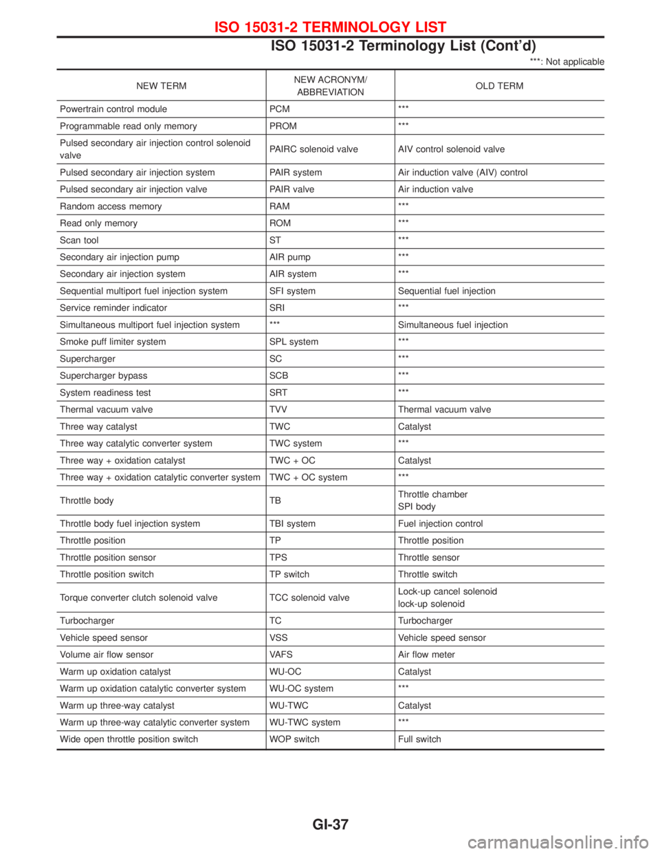
***: Not applicable
NEW TERMNEW ACRONYM/
ABBREVIATIONOLD TERM
Powertrain control module PCM ***
Programmable read only memory PROM ***
Pulsed secondary air injection control solenoid
valvePAIRC solenoid valve AIV control solenoid valve
Pulsed secondary air injection system PAIR system Air induction valve (AIV) control
Pulsed secondary air injection valve PAIR valve Air induction valve
Random access memory RAM ***
Read only memory ROM ***
Scan tool ST ***
Secondary air injection pump AIR pump ***
Secondary air injection system AIR system ***
Sequential multiport fuel injection system SFI system Sequential fuel injection
Service reminder indicator SRI ***
Simultaneous multiport fuel injection system *** Simultaneous fuel injection
Smoke puff limiter system SPL system ***
Supercharger SC ***
Supercharger bypass SCB ***
System readiness test SRT ***
Thermal vacuum valve TVV Thermal vacuum valve
Three way catalyst TWC Catalyst
Three way catalytic converter system TWC system ***
Three way + oxidation catalyst TWC + OC Catalyst
Three way + oxidation catalytic converter system TWC + OC system ***
Throttle body TBThrottle chamber
SPI body
Throttle body fuel injection system TBI system Fuel injection control
Throttle position TP Throttle position
Throttle position sensor TPS Throttle sensor
Throttle position switch TP switch Throttle switch
Torque converter clutch solenoid valve TCC solenoid valveLock-up cancel solenoid
lock-up solenoid
Turbocharger TC Turbocharger
Vehicle speed sensor VSS Vehicle speed sensor
Volume air flow sensor VAFS Air flow meter
Warm up oxidation catalyst WU-OC Catalyst
Warm up oxidation catalytic converter system WU-OC system ***
Warm up three-way catalyst WU-TWC Catalyst
Warm up three-way catalytic converter system WU-TWC system ***
Wide open throttle position switch WOP switch Full switch
ISO 15031-2 TERMINOLOGY LIST
ISO 15031-2 Terminology List (Cont'd)
GI-37
Page 1353 of 1767
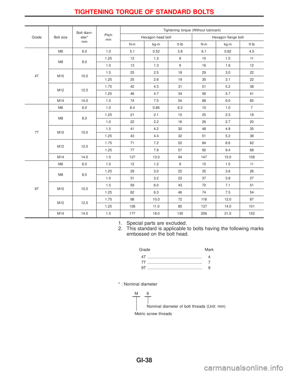
Grade Bolt sizeBolt diam-
eter*
mmPitch
mmTightening torque (Without lubricant)
Hexagon head bolt Hexagon flange bolt
N×m kg-m ft-lb N×m kg-m ft-lb
4TM6 6.0 1.0 5.1 0.52 3.8 6.1 0.62 4.5
M8 8.01.25 13 1.3 9 15 1.5 11
1.0 13 1.3 9 16 1.6 12
M10 10.01.5 25 2.5 18 29 3.0 22
1.25 25 2.6 19 30 3.1 22
M12 12.01.75 42 4.3 31 51 5.2 38
1.25 46 4.7 34 56 5.7 41
M14 14.0 1.5 74 7.5 54 88 9.0 65
7TM6 6.0 1.0 8.4 0.86 6.2 10 1.0 7
M8 8.01.25 21 2.1 15 25 2.5 18
1.0 22 2.2 16 26 2.7 20
M10 10.01.5 41 4.2 30 48 4.9 35
1.25 43 4.4 32 51 5.2 38
M12 12.01.75 71 7.2 52 84 8.6 62
1.25 77 7.9 57 92 9.4 68
M14 14.0 1.5 127 13.0 94 147 15.0 108
9TM6 6.0 1.0 12 1.2 9 15 1.5 11
M8 8.01.25 29 3.0 22 35 3.6 26
1.0 31 3.2 23 37 3.8 27
M10 10.01.5 59 6.0 43 70 7.1 51
1.25 62 6.3 46 74 7.5 54
M12 12.01.75 98 10.0 72 118 12.0 87
1.25 108 11.0 80 137 14.0 101
M14 14.0 1.5 177 18.0 130 206 21.0 152
1. Special parts are excluded.
2. This standard is applicable to bolts having the following marks
embossed on the bolt head.
Grade Mark
4T .................................................
7T .................................................
9T .................................................4
7
9
* : Nominal diameter
M6
Nominal diameter of bolt threads (Unit: mm)
Metric screw threads
TIGHTENING TORQUE OF STANDARD BOLTS
GI-38
Page 1354 of 1767
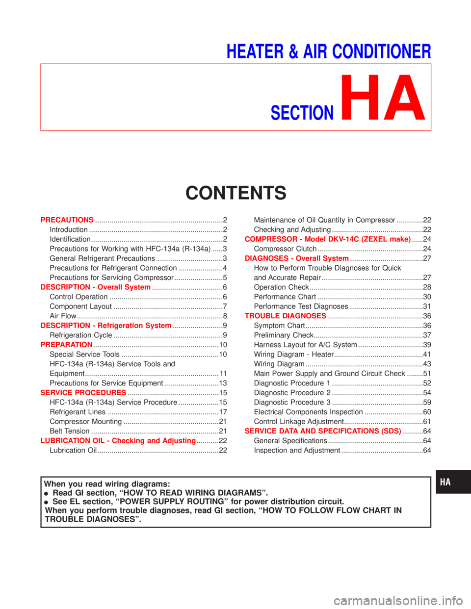
HEATER & AIR CONDITIONER
SECTION
HA
CONTENTS
PRECAUTIONS...............................................................2
Introduction ..................................................................2
Identification .................................................................2
Precautions for Working with HFC-134a (R-134a) .....3
General Refrigerant Precautions .................................3
Precautions for Refrigerant Connection ......................4
Precautions for Servicing Compressor ........................5
DESCRIPTION - Overall System...................................6
Control Operation ........................................................6
Component Layout ......................................................7
Air Flow ........................................................................8
DESCRIPTION - Refrigeration System.........................9
Refrigeration Cycle ......................................................9
PREPARATION..............................................................10
Special Service Tools ................................................10
HFC-134a (R-134a) Service Tools and
Equipment .................................................................. 11
Precautions for Service Equipment ...........................13
SERVICE PROCEDURES.............................................15
HFC-134a (R-134a) Service Procedure ....................15
Refrigerant Lines .......................................................17
Compressor Mounting ...............................................21
Belt Tension ...............................................................21
LUBRICATION OIL - Checking and Adjusting...........22
Lubrication Oil ............................................................22Maintenance of Oil Quantity in Compressor .............22
Checking and Adjusting .............................................22
COMPRESSOR - Model DKV-14C (ZEXEL make)......24
Compressor Clutch ....................................................24
DIAGNOSES - Overall System....................................27
How to Perform Trouble Diagnoses for Quick
and Accurate Repair ..................................................27
Operation Check ........................................................28
Performance Chart ....................................................30
Performance Test Diagnoses ....................................31
TROUBLE DIAGNOSES...............................................36
Symptom Chart ..........................................................36
Preliminary Check......................................................37
Harness Layout for A/C System ................................39
Wiring Diagram - Heater............................................41
Wiring Diagram ..........................................................43
Main Power Supply and Ground Circuit Check ........51
Diagnostic Procedure 1 .............................................52
Diagnostic Procedure 2 .............................................54
Diagnostic Procedure 3 .............................................59
Electrical Components Inspection .............................60
Control Linkage Adjustment.......................................61
SERVICE DATA AND SPECIFICATIONS (SDS)..........64
General Specifications ...............................................64
Inspection and Adjustment ........................................64
When you read wiring diagrams:
IRead GI section, ªHOW TO READ WIRING DIAGRAMSº.
ISee EL section, ªPOWER SUPPLY ROUTINGº for power distribution circuit.
When you perform trouble diagnoses, read GI section, ªHOW TO FOLLOW FLOW CHART IN
TROUBLE DIAGNOSESº.
Page 1355 of 1767
Introduction
To prevent the ozone layer from being destroyed, the HFC-134a (R-134a) refrigerant has replaced the previ-
ously used CFC-12 (R-12).
The new and previous service tools, refrigerant, lubricant, etc. are not interchangeable due to differences in
their physical properties and characteristics.
Always service the HFC-134a (R-134a) air conditioning system using the specified tools, lubricant and
refrigerant, observing the following precautions:
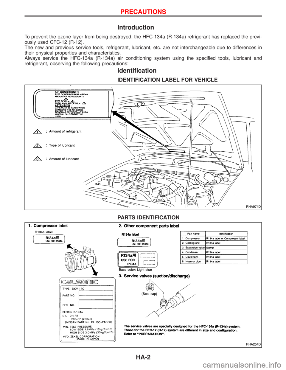
Identification
IDENTIFICATION LABEL FOR VEHICLE
PARTS IDENTIFICATION
RHA974D
RHA254D
PRECAUTIONS
HA-2
Page 1356 of 1767
Precautions for Working with HFC-134a
(R-134a)
WARNING:
ICFC-12 (R-12) refrigerant and HFC-134a (R-134a) refrigerant must never be mixed, even in the
smallest amounts, as they are incompatible with each other. If the refrigerants are mixed, com-
pressor failure is likely to occur.
IUse only specified lubrication oil for the HFC-134a (R-134a) A/C system and HFC-134a (R-134a)
components. If lubrication oil other than that specified is used, compressor failure is likely to
occur.
IThe specified HFC-134a (R-134a) lubrication oil absorbs moisture from the atmosphere at a rapid
rate, therefore the following handling precautions must be observed:
a: When removing refrigerant components from a vehicle, immediately cap (seal) the component
to minimize the entry of moisture from the atmosphere.
b: When installing refrigerant components to a vehicle, do not remove the caps (unseal) until
just before connecting the components. Also, complete the connection of all refrigerant loop
components as quickly as possible to minimize the entry of moisture into the system.
c: Use the specified lubrication oil from a sealed container only. Containers must be re-sealed
immediately after dispensing the lubrication oil. Lubrication oil in containers which are not
properly sealed will become moisture saturated, and such lubrication oil is no longer suitable
for use and should be properly disposed of.
d: Avoid breathing A/C refrigerant and lubricant vapor or mist. Exposure may irritate eyes, nose
and throat. Use only approved recovery/recycling equipment to discharge HFC-134a (R-134a)
system. If accidental system discharge occurs, ventilate work area before resuming service.
Additional health and safety information may be obtained from refrigerant and lubricant
manufacturers.
e: Do not allow lubrication oil (Nissan A/C System Oil Type S or Type R) to come in contact with
styrofoam parts. Damage may result.
General Refrigerant Precautions
WARNING:
IDo not release refrigerant into the air. Use approved recovery/recycling equipment to capture the
refrigerant every time an air conditioning system is discharged.
IAlways wear eye and hand protection (goggles and gloves) when working with any refrigerant or
air conditioning system.
IDo not store or heat refrigerant containers above 52ÉC (125ÉF).
IDo not heat a refrigerant container with an open flame; if container warming is required, place the
bottom of the container in a warm pail of water.
IDo not drop, puncture, or incinerate refrigerant containers.
IKeep refrigerant away from open flames: poisonous gas will be produced if refrigerant burns.
IRefrigerant will displace oxygen, therefore be certain to work in well ventilated areas to prevent
suffocation.
IDo not introduce compressed air to any refrigerant container or refrigerant component.
PRECAUTIONS
HA-3
Page 1357 of 1767
Precautions for Refrigerant Connection
WARNING:
Make sure all refrigerant is discharged into the recycling equipment and the pressure in the system
is less than atmospheric. Then gradually loosen the discharge side hose fitting and remove it.
CAUTION:
When replacing or cleaning refrigerant cycle components, observe the following.
IDo not leave compressor on its side or upside down for more than 10 minutes, as compressor oil
will enter low pressure chamber.
IWhen connecting tubes, always use a torque wrench and a back-up wrench.
IAfter disconnecting tubes, plug all openings immediately to prevent entrance of dirt and moisture.
IWhen installing an air conditioner in the vehicle, the pipes must be connected at the final stage of
the operation. The seal caps of the pipes and other components must not be removed until their
removal is required for connection.
ITo prevent the condensation of moisture inside A/C components, components stored in cool areas
should be allowed to warm to the working area temperature before removing the seal caps.
IThoroughly remove moisture from the refrigeration system before charging the refrigerant.
IAlways replace used O-rings.
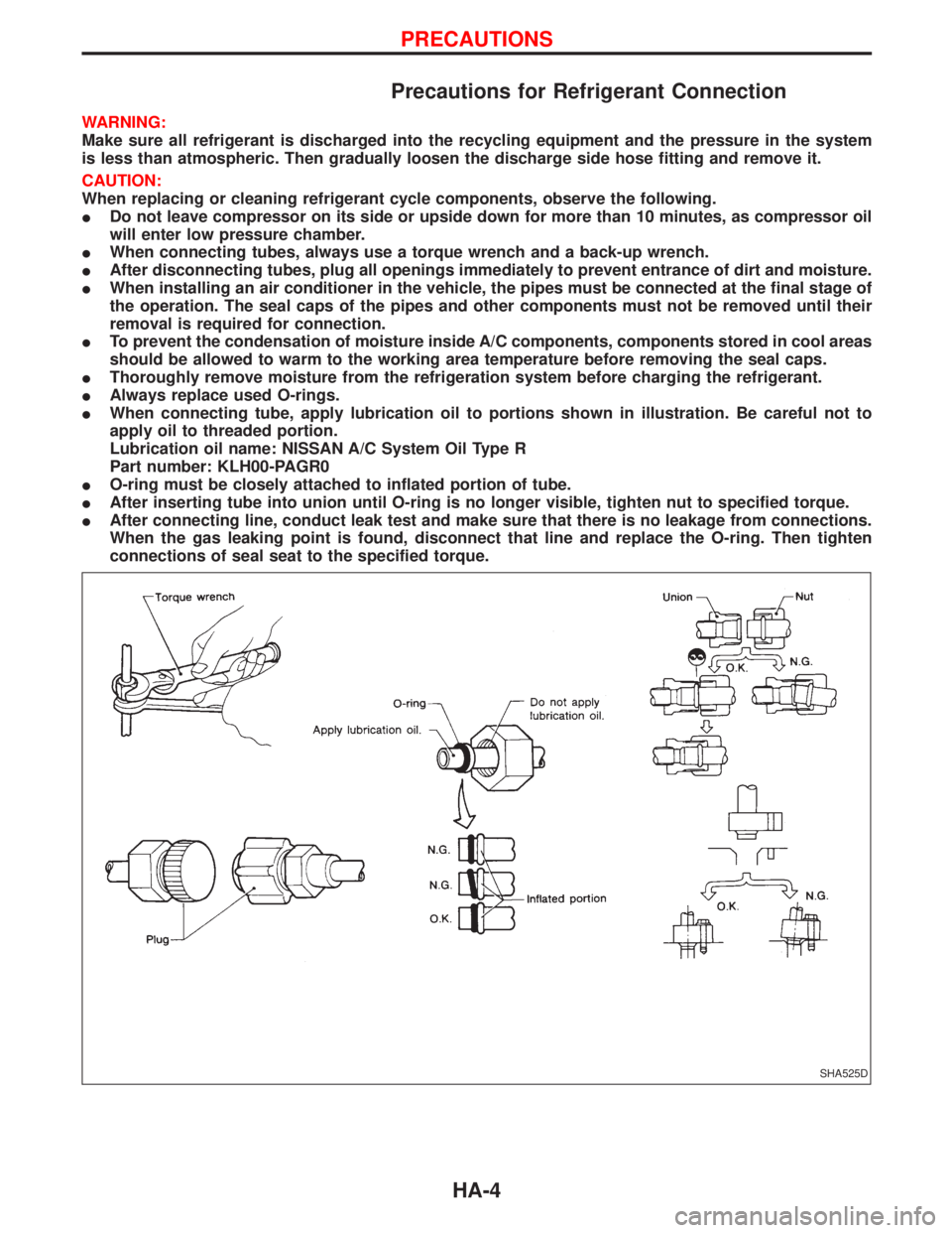
IWhen connecting tube, apply lubrication oil to portions shown in illustration. Be careful not to
apply oil to threaded portion.
Lubrication oil name: NISSAN A/C System Oil Type R
Part number: KLH00-PAGR0
IO-ring must be closely attached to inflated portion of tube.
IAfter inserting tube into union until O-ring is no longer visible, tighten nut to specified torque.
IAfter connecting line, conduct leak test and make sure that there is no leakage from connections.
When the gas leaking point is found, disconnect that line and replace the O-ring. Then tighten
connections of seal seat to the specified torque.
SHA525D
PRECAUTIONS
HA-4
Page 1358 of 1767
Precautions for Servicing Compressor
IAttach a blind plug to the suction port (low pressure) and discharge port (high pressure) of the
compressor to prevent oil from leaking out and dust from getting inside.
IWhen the compressor is removed, store it under the same condition as it is when mounted on the
car.
IWhen replacing or repairing compressor, be sure to remove oil from the compressor and check
the oil quantity extracted.
IWhen replacing with a new compressor, be sure to remove oil from the new compressor so that
the quantity of oil remaining in the new compressor is equal to the quantity collected from the
removed compressor. See the section ªLUBRICATION OILº.
IPay attention so as not to allow dirt and oil to attach on the friction surfaces between clutch and
pulley. If the surface is contaminated, with oil, wipe it off by using a clean waste cloth moistened
with thinner.
IAfter completing the compressor service operation, be sure to rotate the compressor shaft more
than five turns in both directions by hand to equalize oil distribution inside the compressor, then
run the compressor for about one hour by idling the engine.
IWhen the compressor magnet clutch has been replaced, be sure to check the magnet clutch for
normal operation by applying voltage to the clutch.
PRECAUTIONS
HA-5
Page 1359 of 1767
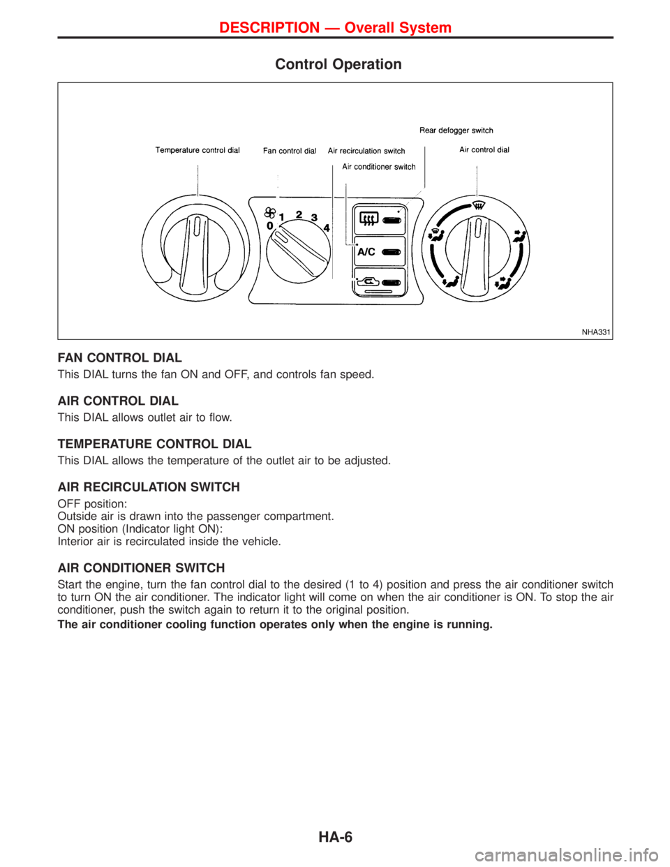
Control Operation
FAN CONTROL DIAL
This DIAL turns the fan ON and OFF, and controls fan speed.
AIR CONTROL DIAL
This DIAL allows outlet air to flow.
TEMPERATURE CONTROL DIAL
This DIAL allows the temperature of the outlet air to be adjusted.
AIR RECIRCULATION SWITCH
OFF position:
Outside air is drawn into the passenger compartment.
ON position (Indicator light ON):
Interior air is recirculated inside the vehicle.
AIR CONDITIONER SWITCH
Start the engine, turn the fan control dial to the desired (1 to 4) position and press the air conditioner switch
to turn ON the air conditioner. The indicator light will come on when the air conditioner is ON. To stop the air
conditioner, push the switch again to return it to the original position.
The air conditioner cooling function operates only when the engine is running.
NHA331
DESCRIPTION Ð Overall System
HA-6
Page 1360 of 1767

Component Layout
NHA339
DESCRIPTION Ð Overall System
HA-7