fuses NISSAN TIIDA 2007 Service User Guide
[x] Cancel search | Manufacturer: NISSAN, Model Year: 2007, Model line: TIIDA, Model: NISSAN TIIDA 2007Pages: 5883, PDF Size: 78.95 MB
Page 3042 of 5883
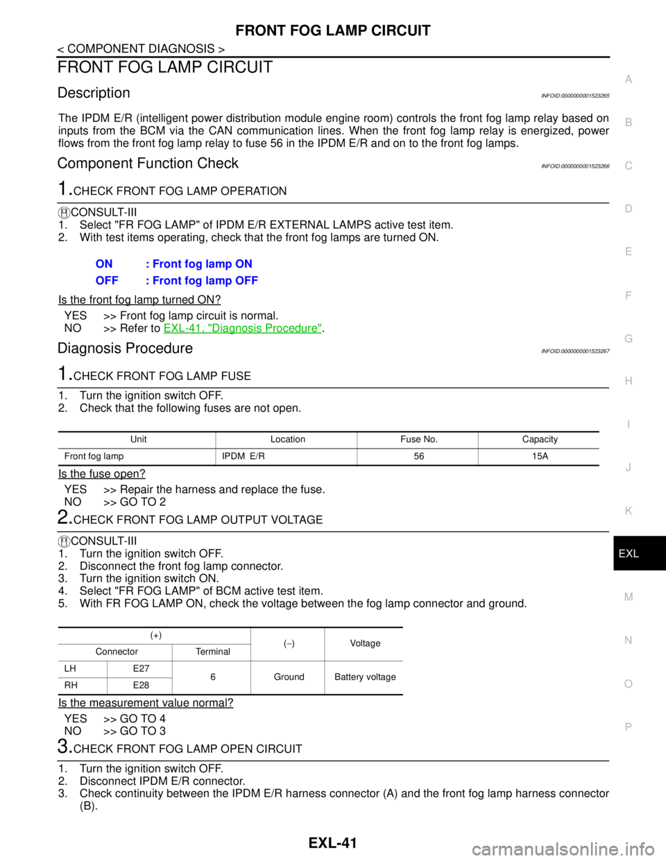
FRONT FOG LAMP CIRCUIT
EXL-41
< COMPONENT DIAGNOSIS >
C
D
E
F
G
H
I
J
K
MA
B
EXL
N
O
P
FRONT FOG LAMP CIRCUIT
DescriptionINFOID:0000000001523265
The IPDM E/R (intelligent power distribution module engine room) controls the front fog lamp relay based on
inputs from the BCM via the CAN communication lines. When the front fog lamp relay is energized, power
flows from the front fog lamp relay to fuse 56 in the IPDM E/R and on to the front fog lamps.
Component Function CheckINFOID:0000000001523266
1.CHECK FRONT FOG LAMP OPERATION
CONSULT-III
1. Select "FR FOG LAMP" of IPDM E/R EXTERNAL LAMPS active test item.
2. With test items operating, check that the front fog lamps are turned ON.
Is the front fog lamp turned ON?
YES >> Front fog lamp circuit is normal.
NO >> Refer to EXL-41, "
Diagnosis Procedure".
Diagnosis ProcedureINFOID:0000000001523267
1.CHECK FRONT FOG LAMP FUSE
1. Turn the ignition switch OFF.
2. Check that the following fuses are not open.
Is the fuse open?
YES >> Repair the harness and replace the fuse.
NO >> GO TO 2
2.CHECK FRONT FOG LAMP OUTPUT VOLTAGE
CONSULT-III
1. Turn the ignition switch OFF.
2. Disconnect the front fog lamp connector.
3. Turn the ignition switch ON.
4. Select "FR FOG LAMP" of BCM active test item.
5. With FR FOG LAMP ON, check the voltage between the fog lamp connector and ground.
Is the measurement value normal?
YES >> GO TO 4
NO >> GO TO 3
3.CHECK FRONT FOG LAMP OPEN CIRCUIT
1. Turn the ignition switch OFF.
2. Disconnect IPDM E/R connector.
3. Check continuity between the IPDM E/R harness connector (A) and the front fog lamp harness connector
(B).ON : Front fog lamp ON
OFF : Front fog lamp OFF
Unit Location Fuse No. Capacity
Front fog lamp IPDM E/R 56 15A
(+)
(−)Voltage
Connector Terminal
LH E27
6 Ground Battery voltage
RH E28
Page 3353 of 5883
HAC-20
< COMPONENT DIAGNOSIS >[MANUAL AIR CONDITIONER]
BLOWER MOTOR
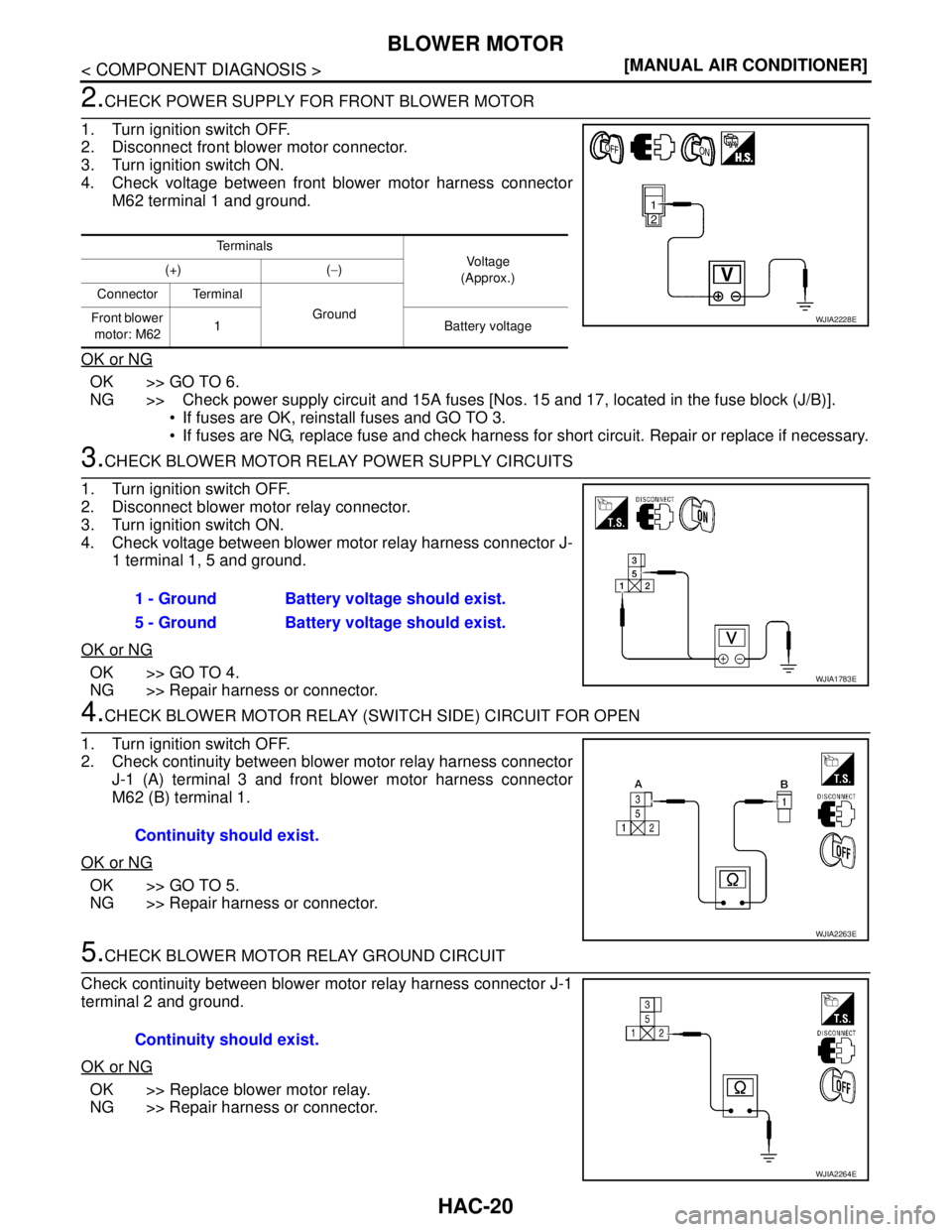
2.CHECK POWER SUPPLY FOR FRONT BLOWER MOTOR
1. Turn ignition switch OFF.
2. Disconnect front blower motor connector.
3. Turn ignition switch ON.
4. Check voltage between front blower motor harness connector
M62 terminal 1 and ground.
OK or NG
OK >> GO TO 6.
NG >> Check power supply circuit and 15A fuses [Nos. 15 and 17, located in the fuse block (J/B)].
If fuses are OK, reinstall fuses and GO TO 3.
If fuses are NG, replace fuse and check harness for short circuit. Repair or replace if necessary.
3.CHECK BLOWER MOTOR RELAY POWER SUPPLY CIRCUITS
1. Turn ignition switch OFF.
2. Disconnect blower motor relay connector.
3. Turn ignition switch ON.
4. Check voltage between blower motor relay harness connector J-
1 terminal 1, 5 and ground.
OK or NG
OK >> GO TO 4.
NG >> Repair harness or connector.
4.CHECK BLOWER MOTOR RELAY (SWITCH SIDE) CIRCUIT FOR OPEN
1. Turn ignition switch OFF.
2. Check continuity between blower motor relay harness connector
J-1 (A) terminal 3 and front blower motor harness connector
M62 (B) terminal 1.
OK or NG
OK >> GO TO 5.
NG >> Repair harness or connector.
5.CHECK BLOWER MOTOR RELAY GROUND CIRCUIT
Check continuity between blower motor relay harness connector J-1
terminal 2 and ground.
OK or NG
OK >> Replace blower motor relay.
NG >> Repair harness or connector.
Te r m i n a l s
Vo l ta g e
(Approx.) (+) (−)
Connector Terminal
Ground
Front blower
motor: M621 Battery voltage
WJIA2228E
1 - Ground Battery voltage should exist.
5 - Ground Battery voltage should exist.
WJIA1783E
Continuity should exist.
WJIA2263E
Continuity should exist.
WJIA2264E
Page 3368 of 5883
PTC HEATER CONTROL SYSTEM
HAC-35
< COMPONENT DIAGNOSIS >[MANUAL AIR CONDITIONER]
C
D
E
F
G
H
J
K
L
MA
B
HAC
N
O
P
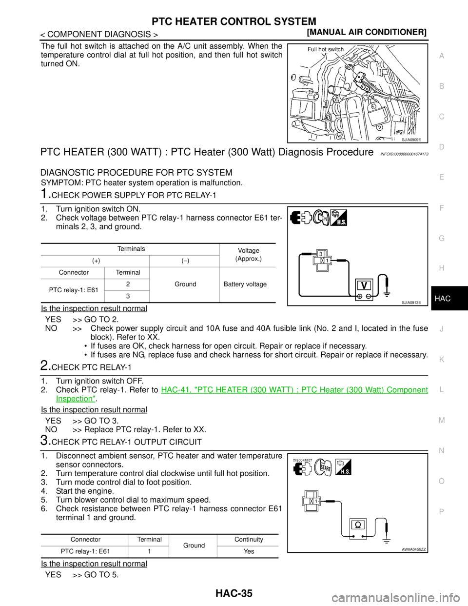
The full hot switch is attached on the A/C unit assembly. When the
temperature control dial at full hot position, and then full hot switch
turned ON.
PTC HEATER (300 WATT) : PTC Heater (300 Watt) Diagnosis ProcedureINFOID:0000000001674173
DIAGNOSTIC PROCEDURE FOR PTC SYSTEM
SYMPTOM: PTC heater system operation is malfunction.
1.CHECK POWER SUPPLY FOR PTC RELAY-1
1. Turn ignition switch ON.
2. Check voltage between PTC relay-1 harness connector E61 ter-
minals 2, 3, and ground.
Is the inspection result normal
YES >> GO TO 2.
NO >> Check power supply circuit and 10A fuse and 40A fusible link (No. 2 and I, located in the fuse
block). Refer to XX.
If fuses are OK, check harness for open circuit. Repair or replace if necessary.
If fuses are NG, replace fuse and check harness for short circuit. Repair or replace if necessary.
2.CHECK PTC RELAY-1
1. Turn ignition switch OFF.
2. Check PTC relay-1. Refer to HAC-41, "
PTC HEATER (300 WATT) : PTC Heater (300 Watt) Component
Inspection".
Is the inspection result normal
YES >> GO TO 3.
NO >> Replace PTC relay-1. Refer to XX.
3.CHECK PTC RELAY-1 OUTPUT CIRCUIT
1. Disconnect ambient sensor, PTC heater and water temperature
sensor connectors.
2. Turn temperature control dial clockwise until full hot position.
3. Turn mode control dial to foot position.
4. Start the engine.
5. Turn blower control dial to maximum speed.
6. Check resistance between PTC relay-1 harness connector E61
terminal 1 and ground.
Is the inspection result normal
YES >> GO TO 5.
SJIA0909E
Te r m i n a l s
Vo l ta g e
(Approx.)
(+) (−)
Connector Terminal
Ground Battery voltage
PTC relay-1: E612
3
SJIA0913E
Connector Terminal
GroundContinuity
PTC relay-1: E61 1 Yes
AWIIA0455ZZ
Page 3379 of 5883
HAC-46
< COMPONENT DIAGNOSIS >[MANUAL AIR CONDITIONER]
PTC HEATER CONTROL SYSTEM
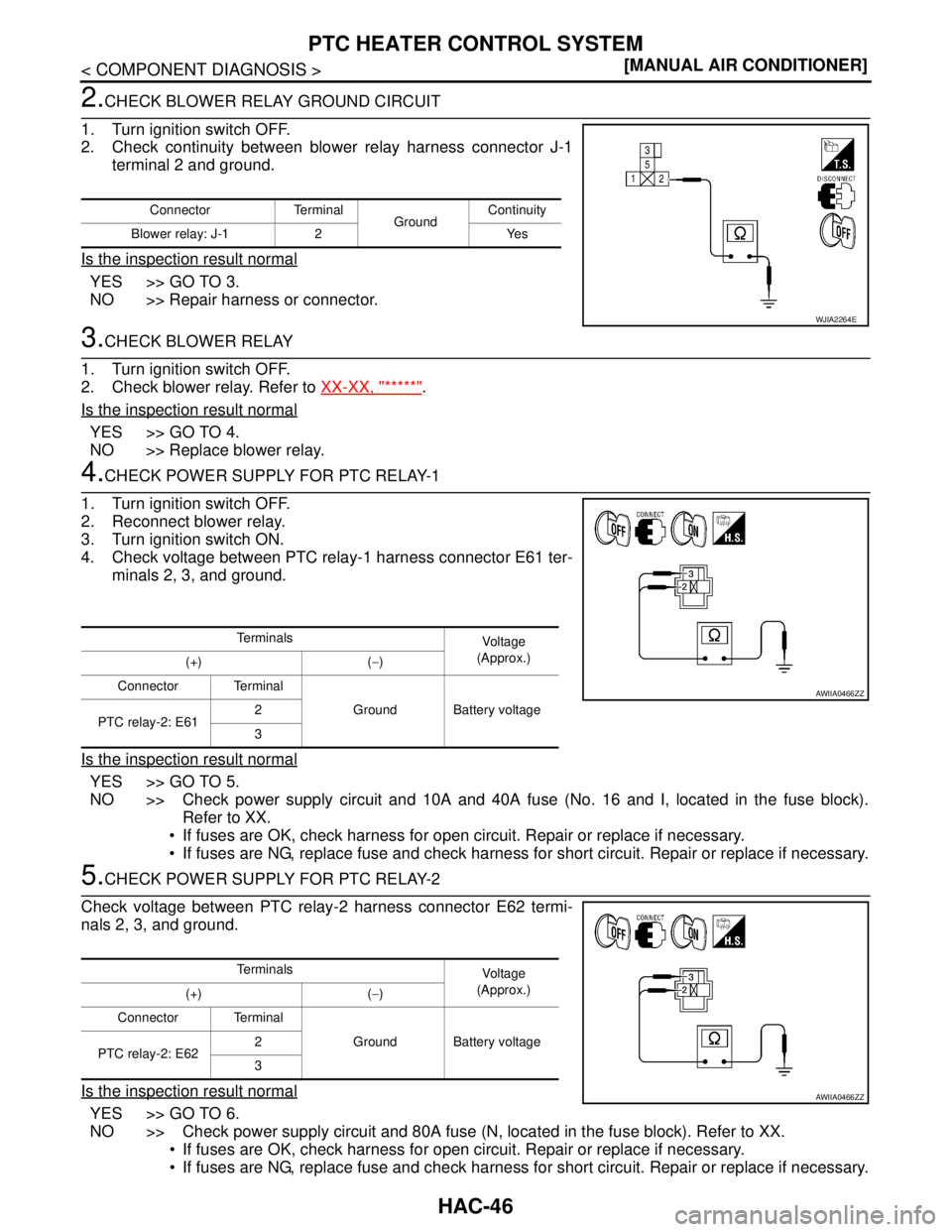
2.CHECK BLOWER RELAY GROUND CIRCUIT
1. Turn ignition switch OFF.
2. Check continuity between blower relay harness connector J-1
terminal 2 and ground.
Is the inspection result normal
YES >> GO TO 3.
NO >> Repair harness or connector.
3.CHECK BLOWER RELAY
1. Turn ignition switch OFF.
2. Check blower relay. Refer to XX-XX, "*****"
.
Is the inspection result normal
YES >> GO TO 4.
NO >> Replace blower relay.
4.CHECK POWER SUPPLY FOR PTC RELAY-1
1. Turn ignition switch OFF.
2. Reconnect blower relay.
3. Turn ignition switch ON.
4. Check voltage between PTC relay-1 harness connector E61 ter-
minals 2, 3, and ground.
Is the inspection result normal
YES >> GO TO 5.
NO >> Check power supply circuit and 10A and 40A fuse (No. 16 and I, located in the fuse block).
Refer to XX.
If fuses are OK, check harness for open circuit. Repair or replace if necessary.
If fuses are NG, replace fuse and check harness for short circuit. Repair or replace if necessary.
5.CHECK POWER SUPPLY FOR PTC RELAY-2
Check voltage between PTC relay-2 harness connector E62 termi-
nals 2, 3, and ground.
Is the inspection result normal
YES >> GO TO 6.
NO >> Check power supply circuit and 80A fuse (N, located in the fuse block). Refer to XX.
If fuses are OK, check harness for open circuit. Repair or replace if necessary.
If fuses are NG, replace fuse and check harness for short circuit. Repair or replace if necessary.
Connector Terminal
GroundContinuity
Blower relay: J-1 2 Yes
WJIA2264E
Te r m i n a l s
Voltag e
(Approx.)
(+) (−)
Connector Terminal
Ground Battery voltage
PTC relay-2: E612
3
AWIIA0466ZZ
Te r m i n a l s
Voltag e
(Approx.)
(+) (−)
Connector Terminal
Ground Battery voltage
PTC relay-2: E622
3
AWIIA0466ZZ
Page 3380 of 5883
PTC HEATER CONTROL SYSTEM
HAC-47
< COMPONENT DIAGNOSIS >[MANUAL AIR CONDITIONER]
C
D
E
F
G
H
J
K
L
MA
B
HAC
N
O
P
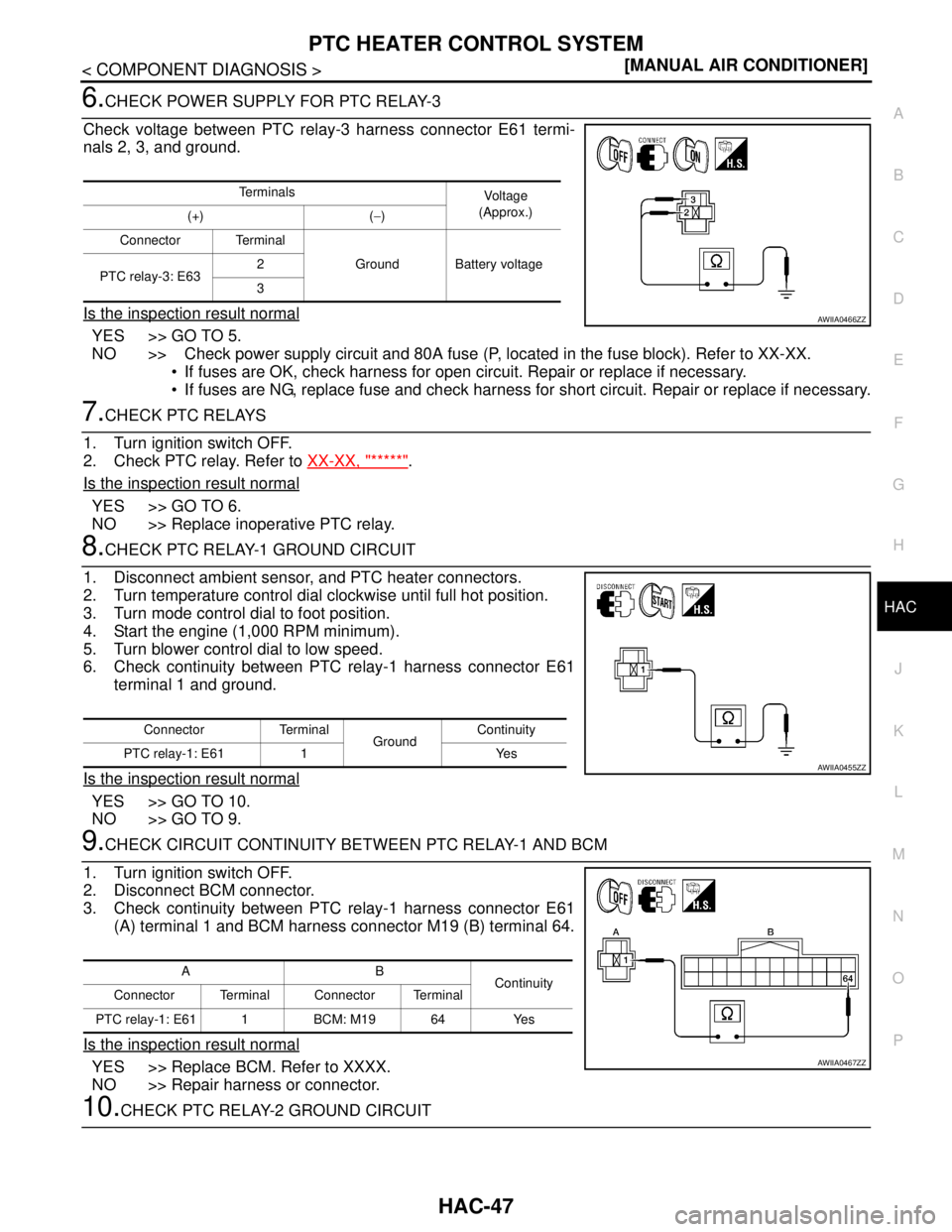
6.CHECK POWER SUPPLY FOR PTC RELAY-3
Check voltage between PTC relay-3 harness connector E61 termi-
nals 2, 3, and ground.
Is the inspection result normal
YES >> GO TO 5.
NO >> Check power supply circuit and 80A fuse (P, located in the fuse block). Refer to XX-XX.
If fuses are OK, check harness for open circuit. Repair or replace if necessary.
If fuses are NG, replace fuse and check harness for short circuit. Repair or replace if necessary.
7.CHECK PTC RELAYS
1. Turn ignition switch OFF.
2. Check PTC relay. Refer to XX-XX, "*****"
.
Is the inspection result normal
YES >> GO TO 6.
NO >> Replace inoperative PTC relay.
8.CHECK PTC RELAY-1 GROUND CIRCUIT
1. Disconnect ambient sensor, and PTC heater connectors.
2. Turn temperature control dial clockwise until full hot position.
3. Turn mode control dial to foot position.
4. Start the engine (1,000 RPM minimum).
5. Turn blower control dial to low speed.
6. Check continuity between PTC relay-1 harness connector E61
terminal 1 and ground.
Is the inspection result normal
YES >> GO TO 10.
NO >> GO TO 9.
9.CHECK CIRCUIT CONTINUITY BETWEEN PTC RELAY-1 AND BCM
1. Turn ignition switch OFF.
2. Disconnect BCM connector.
3. Check continuity between PTC relay-1 harness connector E61
(A) terminal 1 and BCM harness connector M19 (B) terminal 64.
Is the inspection result normal
YES >> Replace BCM. Refer to XXXX.
NO >> Repair harness or connector.
10.CHECK PTC RELAY-2 GROUND CIRCUIT
Te r m i n a l s
Vo l ta g e
(Approx.)
(+) (−)
Connector Terminal
Ground Battery voltage
PTC relay-3: E632
3
AWIIA0466ZZ
Connector Terminal
GroundContinuity
PTC relay-1: E61 1 Yes
AWIIA0455ZZ
AB
Continuity
Connector Terminal Connector Terminal
PTC relay-1: E61 1 BCM: M19 64 Yes
AWIIA0467ZZ
Page 3453 of 5883
HAC-120
< COMPONENT DIAGNOSIS >[AUTO AIR CONDITIONER (W/O NAVI)]
BLOWER MOTOR CONTROL SYSTEM
YES >> GO TO 7.
NO >> Repair as necessary.
7. CHECK INTAKE SENSOR CIRCUIT
Perform diagnostic procedure for the intake sensor circuit. Refer to HAC-139, "
Intake Sensor Diagnosis Pro-
cedure".
Is the inspection result normal?
YES >> GO TO 8.
NO >> Repair as necessary.
8. RECHECK FOR SYMPTOMS
Perform a complete operational check and check for any symptoms. Refer to HAC-87, "
Operational Check".
Does another symptom exist?
YES >> Repair as necessary.
NO >> Replace front air control. Refer to .
Front Blower Motor Diagnosis ProcedureINFOID:0000000001547419
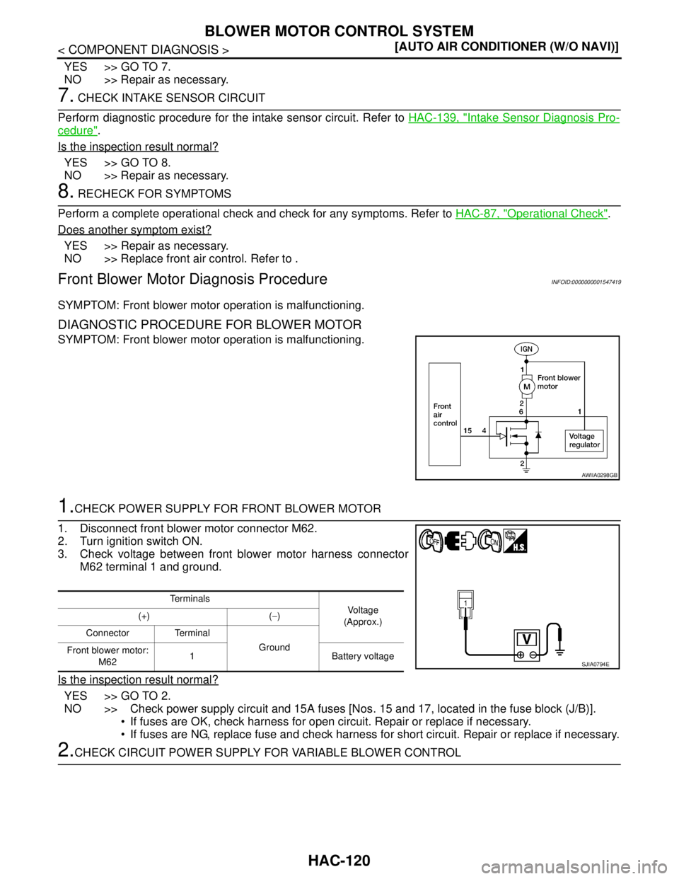
SYMPTOM: Front blower motor operation is malfunctioning.
DIAGNOSTIC PROCEDURE FOR BLOWER MOTOR
SYMPTOM: Front blower motor operation is malfunctioning.
1.CHECK POWER SUPPLY FOR FRONT BLOWER MOTOR
1. Disconnect front blower motor connector M62.
2. Turn ignition switch ON.
3. Check voltage between front blower motor harness connector
M62 terminal 1 and ground.
Is the inspection result normal?
YES >> GO TO 2.
NO >> Check power supply circuit and 15A fuses [Nos. 15 and 17, located in the fuse block (J/B)].
If fuses are OK, check harness for open circuit. Repair or replace if necessary.
If fuses are NG, replace fuse and check harness for short circuit. Repair or replace if necessary.
2.CHECK CIRCUIT POWER SUPPLY FOR VARIABLE BLOWER CONTROL
AWIIA0298GB
Te r m i n a l s
Vol tag e
(Approx.) (+) (−)
Connector Terminal
Ground
Front blower motor:
M621 Battery voltage
SJIA0794E
Page 3477 of 5883
HAC-144
< COMPONENT DIAGNOSIS >[AUTO AIR CONDITIONER (W/O NAVI)]
PTC HEATER CONTROL SYSTEM
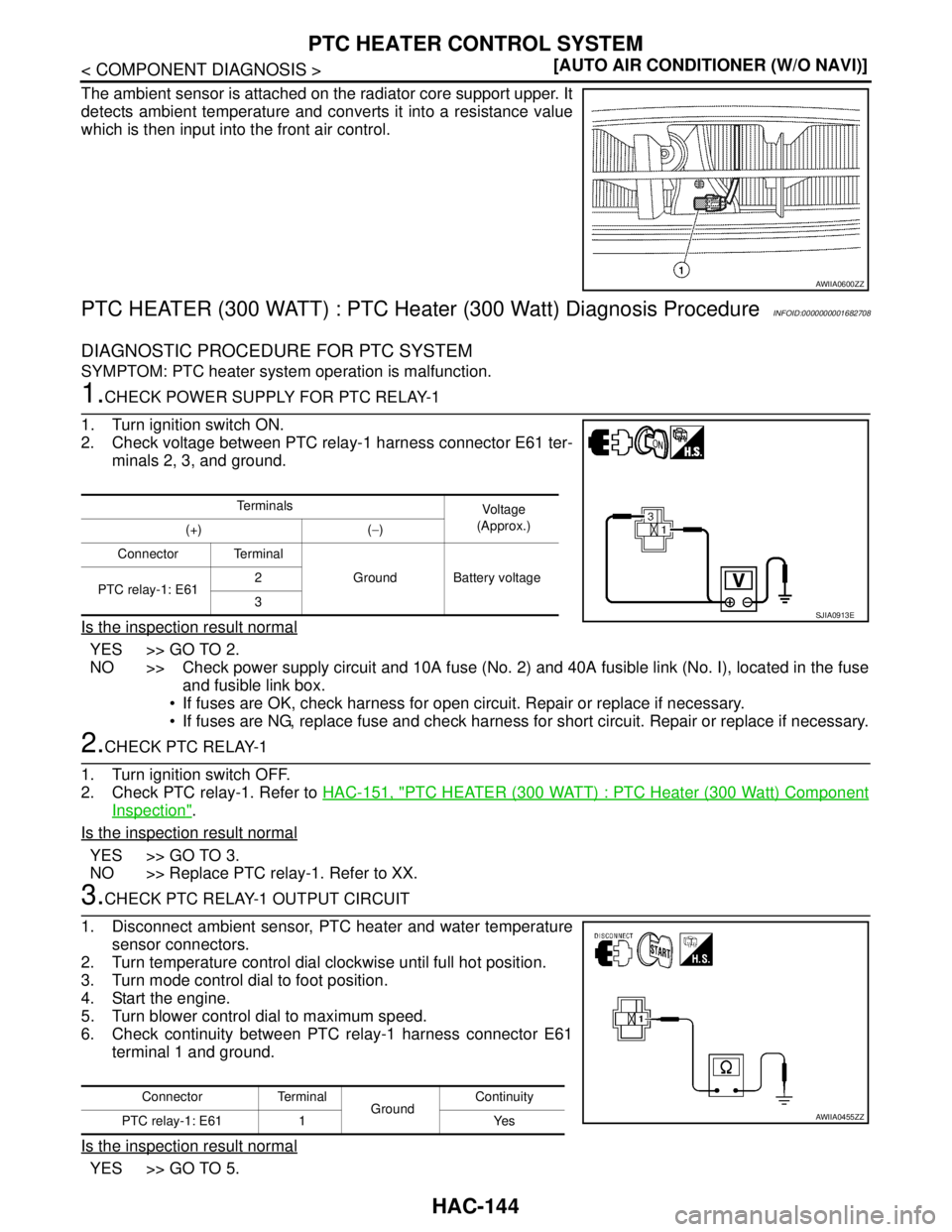
The ambient sensor is attached on the radiator core support upper. It
detects ambient temperature and converts it into a resistance value
which is then input into the front air control.
PTC HEATER (300 WATT) : PTC Heater (300 Watt) Diagnosis ProcedureINFOID:0000000001682708
DIAGNOSTIC PROCEDURE FOR PTC SYSTEM
SYMPTOM: PTC heater system operation is malfunction.
1.CHECK POWER SUPPLY FOR PTC RELAY-1
1. Turn ignition switch ON.
2. Check voltage between PTC relay-1 harness connector E61 ter-
minals 2, 3, and ground.
Is the inspection result normal
YES >> GO TO 2.
NO >> Check power supply circuit and 10A fuse (No. 2) and 40A fusible link (No. I), located in the fuse
and fusible link box.
If fuses are OK, check harness for open circuit. Repair or replace if necessary.
If fuses are NG, replace fuse and check harness for short circuit. Repair or replace if necessary.
2.CHECK PTC RELAY-1
1. Turn ignition switch OFF.
2. Check PTC relay-1. Refer to HAC-151, "
PTC HEATER (300 WATT) : PTC Heater (300 Watt) Component
Inspection".
Is the inspection result normal
YES >> GO TO 3.
NO >> Replace PTC relay-1. Refer to XX.
3.CHECK PTC RELAY-1 OUTPUT CIRCUIT
1. Disconnect ambient sensor, PTC heater and water temperature
sensor connectors.
2. Turn temperature control dial clockwise until full hot position.
3. Turn mode control dial to foot position.
4. Start the engine.
5. Turn blower control dial to maximum speed.
6. Check continuity between PTC relay-1 harness connector E61
terminal 1 and ground.
Is the inspection result normal
YES >> GO TO 5.
AWIIA0600ZZ
Te r m i n a l s
Voltag e
(Approx.)
(+) (−)
Connector Terminal
Ground Battery voltage
PTC relay-1: E612
3
SJIA0913E
Connector Terminal
GroundContinuity
PTC relay-1: E61 1 Yes
AWIIA0455ZZ
Page 3489 of 5883
HAC-156
< COMPONENT DIAGNOSIS >[AUTO AIR CONDITIONER (W/O NAVI)]
PTC HEATER CONTROL SYSTEM
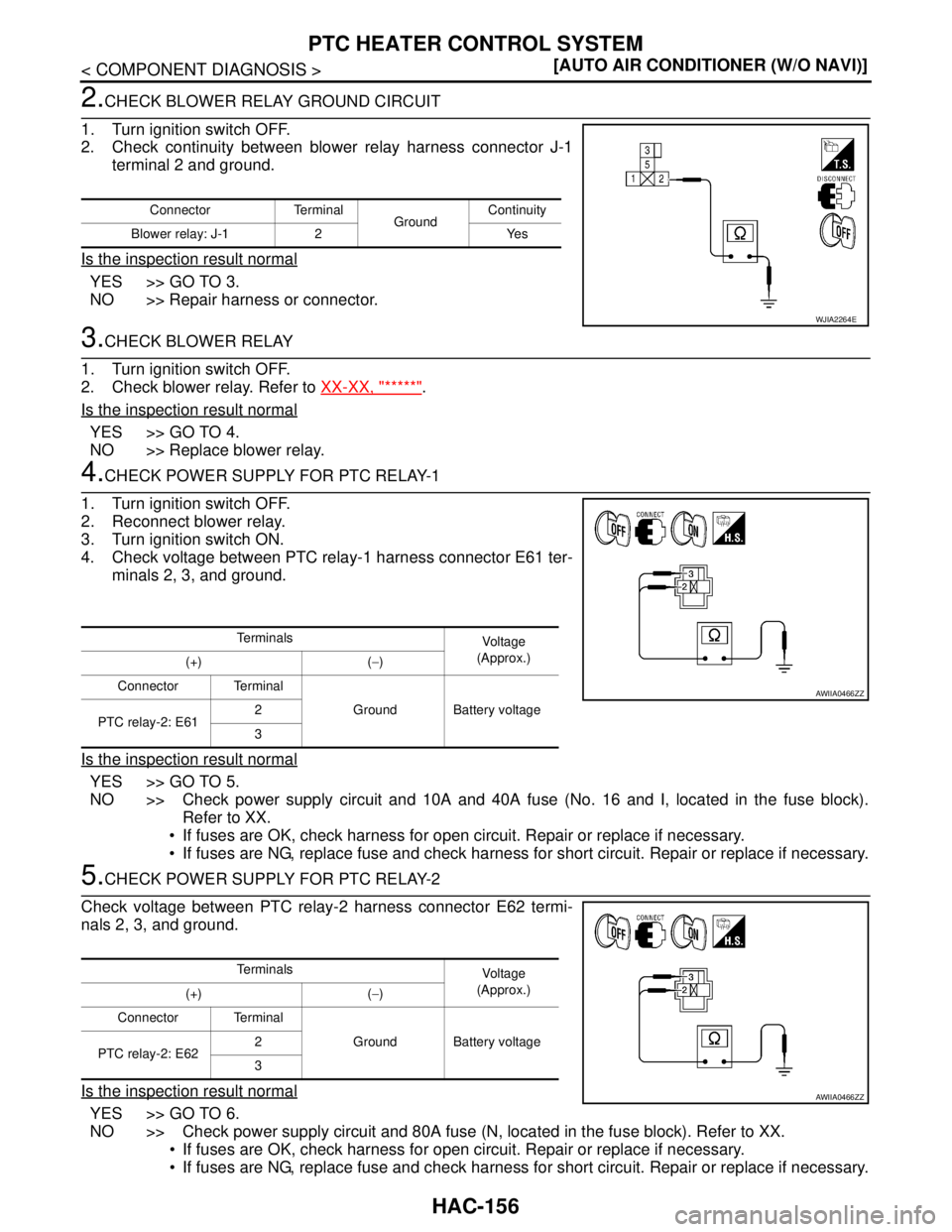
2.CHECK BLOWER RELAY GROUND CIRCUIT
1. Turn ignition switch OFF.
2. Check continuity between blower relay harness connector J-1
terminal 2 and ground.
Is the inspection result normal
YES >> GO TO 3.
NO >> Repair harness or connector.
3.CHECK BLOWER RELAY
1. Turn ignition switch OFF.
2. Check blower relay. Refer to XX-XX, "*****"
.
Is the inspection result normal
YES >> GO TO 4.
NO >> Replace blower relay.
4.CHECK POWER SUPPLY FOR PTC RELAY-1
1. Turn ignition switch OFF.
2. Reconnect blower relay.
3. Turn ignition switch ON.
4. Check voltage between PTC relay-1 harness connector E61 ter-
minals 2, 3, and ground.
Is the inspection result normal
YES >> GO TO 5.
NO >> Check power supply circuit and 10A and 40A fuse (No. 16 and I, located in the fuse block).
Refer to XX.
If fuses are OK, check harness for open circuit. Repair or replace if necessary.
If fuses are NG, replace fuse and check harness for short circuit. Repair or replace if necessary.
5.CHECK POWER SUPPLY FOR PTC RELAY-2
Check voltage between PTC relay-2 harness connector E62 termi-
nals 2, 3, and ground.
Is the inspection result normal
YES >> GO TO 6.
NO >> Check power supply circuit and 80A fuse (N, located in the fuse block). Refer to XX.
If fuses are OK, check harness for open circuit. Repair or replace if necessary.
If fuses are NG, replace fuse and check harness for short circuit. Repair or replace if necessary.
Connector Terminal
GroundContinuity
Blower relay: J-1 2 Yes
WJIA2264E
Te r m i n a l s
Voltag e
(Approx.)
(+) (−)
Connector Terminal
Ground Battery voltage
PTC relay-2: E612
3
AWIIA0466ZZ
Te r m i n a l s
Voltag e
(Approx.)
(+) (−)
Connector Terminal
Ground Battery voltage
PTC relay-2: E622
3
AWIIA0466ZZ
Page 3490 of 5883
PTC HEATER CONTROL SYSTEM
HAC-157
< COMPONENT DIAGNOSIS >[AUTO AIR CONDITIONER (W/O NAVI)]
C
D
E
F
G
H
J
K
L
MA
B
HAC
N
O
P
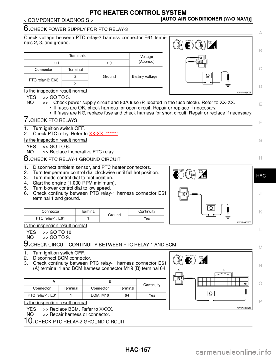
6.CHECK POWER SUPPLY FOR PTC RELAY-3
Check voltage between PTC relay-3 harness connector E61 termi-
nals 2, 3, and ground.
Is the inspection result normal
YES >> GO TO 5.
NO >> Check power supply circuit and 80A fuse (P, located in the fuse block). Refer to XX-XX.
If fuses are OK, check harness for open circuit. Repair or replace if necessary.
If fuses are NG, replace fuse and check harness for short circuit. Repair or replace if necessary.
7.CHECK PTC RELAYS
1. Turn ignition switch OFF.
2. Check PTC relay. Refer to XX-XX, "*****"
.
Is the inspection result normal
YES >> GO TO 6.
NO >> Replace inoperative PTC relay.
8.CHECK PTC RELAY-1 GROUND CIRCUIT
1. Disconnect ambient sensor, and PTC heater connectors.
2. Turn temperature control dial clockwise until full hot position.
3. Turn mode control dial to foot position.
4. Start the engine (1,000 RPM minimum).
5. Turn blower control dial to low speed.
6. Check continuity between PTC relay-1 harness connector E61
terminal 1 and ground.
Is the inspection result normal
YES >> GO TO 10.
NO >> GO TO 9.
9.CHECK CIRCUIT CONTINUITY BETWEEN PTC RELAY-1 AND BCM
1. Turn ignition switch OFF.
2. Disconnect BCM connector.
3. Check continuity between PTC relay-1 harness connector E61
(A) terminal 1 and BCM harness connector M19 (B) terminal 64.
Is the inspection result normal
YES >> Replace BCM. Refer to XXXX.
NO >> Repair harness or connector.
10.CHECK PTC RELAY-2 GROUND CIRCUIT
Te r m i n a l s
Vo l ta g e
(Approx.)
(+) (−)
Connector Terminal
Ground Battery voltage
PTC relay-3: E632
3
AWIIA0466ZZ
Connector Terminal
GroundContinuity
PTC relay-1: E61 1 Yes
AWIIA0455ZZ
AB
Continuity
Connector Terminal Connector Terminal
PTC relay-1: E61 1 BCM: M19 64 Yes
AWIIA0467ZZ
Page 3497 of 5883
HAC-164
< COMPONENT DIAGNOSIS >[AUTO AIR CONDITIONER (W/O NAVI)]
POWER SUPPLY AND GROUND CIRCUIT FOR CONTROLLER
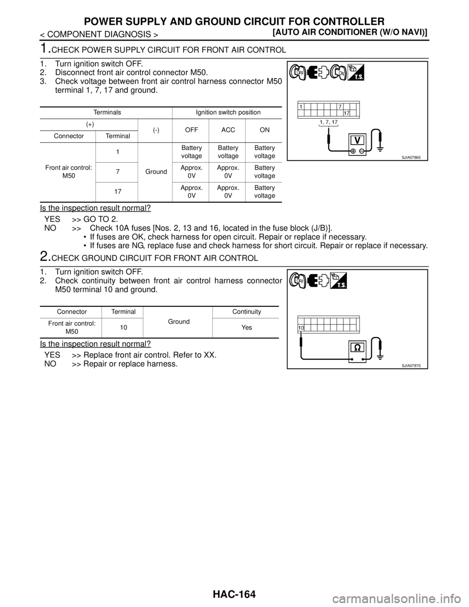
1.CHECK POWER SUPPLY CIRCUIT FOR FRONT AIR CONTROL
1. Turn ignition switch OFF.
2. Disconnect front air control connector M50.
3. Check voltage between front air control harness connector M50
terminal 1, 7, 17 and ground.
Is the inspection result normal?
YES >> GO TO 2.
NO >> Check 10A fuses [Nos. 2, 13 and 16, located in the fuse block (J/B)].
If fuses are OK, check harness for open circuit. Repair or replace if necessary.
If fuses are NG, replace fuse and check harness for short circuit. Repair or replace if necessary.
2.CHECK GROUND CIRCUIT FOR FRONT AIR CONTROL
1. Turn ignition switch OFF.
2. Check continuity between front air control harness connector
M50 terminal 10 and ground.
Is the inspection result normal?
YES >> Replace front air control. Refer to XX.
NO >> Repair or replace harness.
Terminals Ignition switch position
(+)
(-) OFF ACC ON
Connector Terminal
Front air control:
M501
GroundBattery
voltageBattery
voltageBattery
voltage
7Approx.
0VApprox.
0VBattery
voltage
17Approx.
0VApprox.
0VBattery
voltage
SJIA0786E
Connector Terminal
GroundContinuity
Front air control:
M5010 Yes
SJIA0787E