NISSAN TIIDA 2007 Service Repair Manual
Manufacturer: NISSAN, Model Year: 2007, Model line: TIIDA, Model: NISSAN TIIDA 2007Pages: 5883, PDF Size: 78.95 MB
Page 4331 of 5883

MWI-24
< COMPONENT DIAGNOSIS >
DTC U1000 CAN COMMUNICATION
COMPONENT DIAGNOSIS
DTC U1000 CAN COMMUNICATION
DTC LogicINFOID:0000000001374683
DTC DETECTION LOGIC
Diagnosis ProcedureINFOID:0000000001374684
Symptom: Displays “CAN COMM CIRC [U1000]” as a self-diagnosis result of combination meter.
1.CHECK CAN COMMUNICATION
Select “SELF-DIAG RESULTS” mode for “METER/M&A” with CONSULT-III.
>> Go to “LAN system”. Refer to LAN-22, "
Trouble Diagnosis Flow Chart".
DTC CONSULT-III display Detection condition
U1000CAN COMM CIRC
[U1000]When combination meter is not receiving CAN communication signals for 2 seconds or more.
Page 4332 of 5883
MWI
DTC B2205 VEHICLE SPEED CIRCUIT
MWI-25
< COMPONENT DIAGNOSIS >
C
D
E
F
G
H
I
J
K
L
MB A
O
P
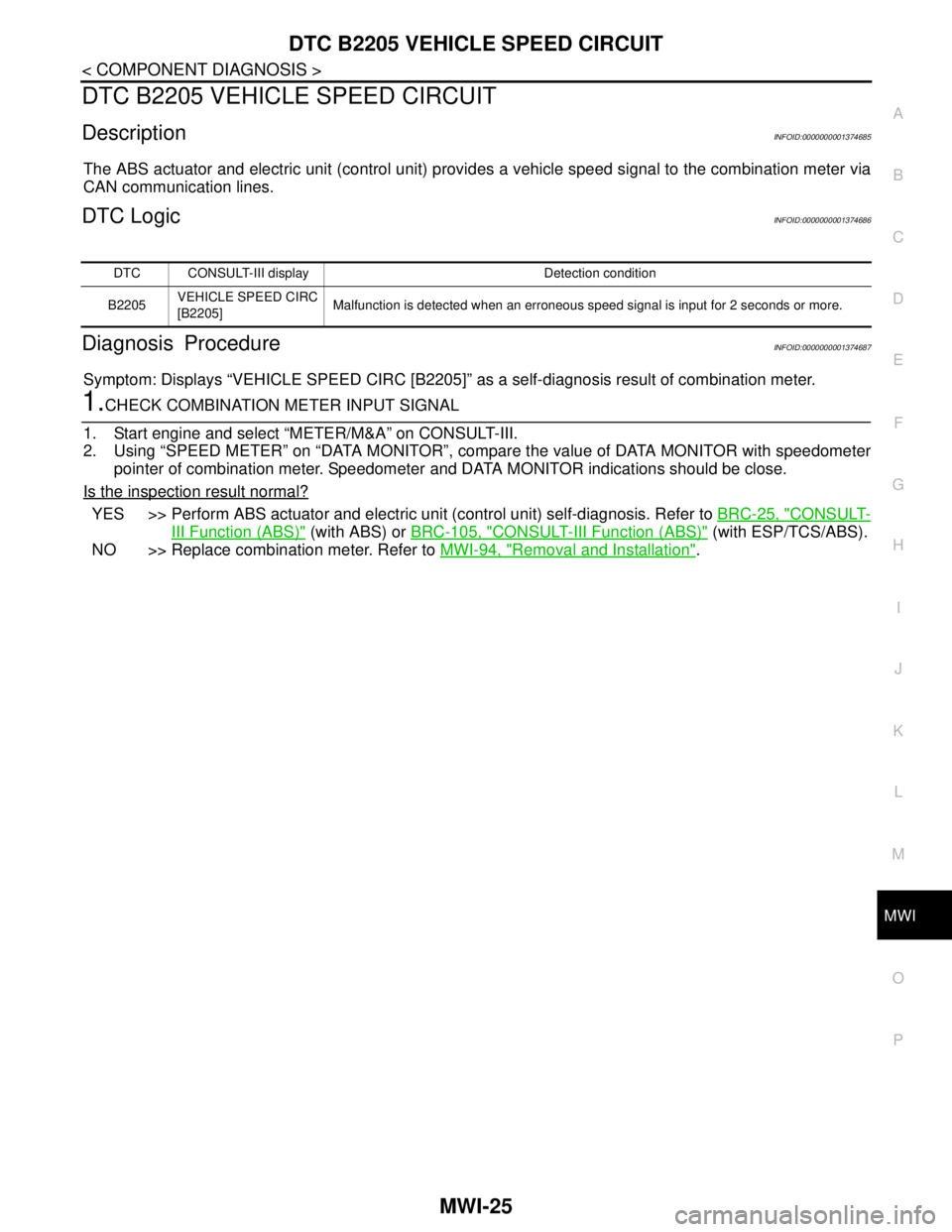
DTC B2205 VEHICLE SPEED CIRCUIT
DescriptionINFOID:0000000001374685
The ABS actuator and electric unit (control unit) provides a vehicle speed signal to the combination meter via
CAN communication lines.
DTC LogicINFOID:0000000001374686
Diagnosis ProcedureINFOID:0000000001374687
Symptom: Displays “VEHICLE SPEED CIRC [B2205]” as a self-diagnosis result of combination meter.
1.CHECK COMBINATION METER INPUT SIGNAL
1. Start engine and select “METER/M&A” on CONSULT-III.
2. Using “SPEED METER” on “DATA MONITOR”, compare the value of DATA MONITOR with speedometer
pointer of combination meter. Speedometer and DATA MONITOR indications should be close.
Is the inspection result normal?
YES >> Perform ABS actuator and electric unit (control unit) self-diagnosis. Refer to BRC-25, "CONSULT-
III Function (ABS)" (with ABS) or BRC-105, "CONSULT-III Function (ABS)" (with ESP/TCS/ABS).
NO >> Replace combination meter. Refer to MWI-94, "
Removal and Installation".
DTC CONSULT-III display Detection condition
B2205VEHICLE SPEED CIRC
[B2205]Malfunction is detected when an erroneous speed signal is input for 2 seconds or more.
Page 4333 of 5883
MWI-26
< COMPONENT DIAGNOSIS >
POWER SUPPLY AND GROUND CIRCUIT
POWER SUPPLY AND GROUND CIRCUIT
COMBINATION METER
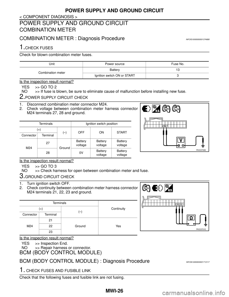
COMBINATION METER : Diagnosis ProcedureINFOID:0000000001374688
1.CHECK FUSES
Check for blown combination meter fuses.
Is the inspection result normal?
YES >> GO TO 2
NO >> If fuse is blown, be sure to eliminate cause of malfunction before installing new fuse.
2.POWER SUPPLY CIRCUIT CHECK
1. Disconnect combination meter connector M24.
2. Check voltage between combination meter harness connector
M24 terminals 27, 28 and ground.
Is the inspection result normal?
YES >> GO TO 3
NO >> Check harness for open between combination meter and fuse.
3.GROUND CIRCUIT CHECK
1. Turn ignition switch OFF.
2. Check continuity between combination meter harness connector
M24 terminals 21, 22, 23 and ground.
Is the inspection result normal?
YES >> Inspection End.
NO >> Repair harness or connector.
BCM (BODY CONTROL MODULE)
BCM (BODY CONTROL MODULE) : Diagnosis ProcedureINFOID:0000000001713117
1. CHECK FUSES AND FUSIBLE LINK
Check that the following fuses and fusible link are not fusing.
Unit Power source Fuse No.
Combination meterBattery 13
Ignition switch ON or START 3
Terminals Ignition switch position
(+)
(–) OFF ON START
Connector Terminal
M2427
GroundBattery
voltageBattery
voltageBattery
voltage
28 0VBattery
voltageBattery
voltage
PKIC0700E
Te r m i n a l s
Continuity (+)
(–)
Connector Terminal
M2421
Ground Yes 22
23
PKIC0701E
Page 4334 of 5883
MWI
POWER SUPPLY AND GROUND CIRCUIT
MWI-27
< COMPONENT DIAGNOSIS >
C
D
E
F
G
H
I
J
K
L
MB A
O
P
Is the fuse fusing?
YES >> Replace the blown fuse or fusible link after repairing the affected circuit if a fuse or fusible link is
blown.
NO >> GO TO 2.
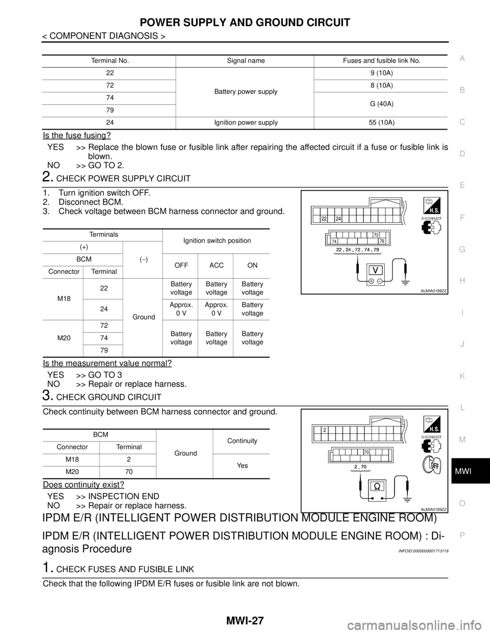
2. CHECK POWER SUPPLY CIRCUIT
1. Turn ignition switch OFF.
2. Disconnect BCM.
3. Check voltage between BCM harness connector and ground.
Is the measurement value normal?
YES >> GO TO 3
NO >> Repair or replace harness.
3. CHECK GROUND CIRCUIT
Check continuity between BCM harness connector and ground.
Does continuity exist?
YES >> INSPECTION END
NO >> Repair or replace harness.
IPDM E/R (INTELLIGENT POWER DISTRIBUTION MODULE ENGINE ROOM)
IPDM E/R (INTELLIGENT POWER DISTRIBUTION MODULE ENGINE ROOM) : Di-
agnosis Procedure
INFOID:0000000001713118
1. CHECK FUSES AND FUSIBLE LINK
Check that the following IPDM E/R fuses or fusible link are not blown.
Terminal No. Signal name Fuses and fusible link No.
22
Battery power supply9 (10A)
728 (10A)
74
G (40A)
79
24 Ignition power supply 55 (10A)
Te r m i n a l s
Ignition switch position
(+)
(−) BCM
OFF ACC ON
Connector Terminal
M1822
GroundBattery
voltageBattery
voltageBattery
voltage
24Approx.
0 VApprox.
0 VBattery
voltage
M2072
Battery
voltageBattery
voltageBattery
voltage 74
79
ALMIA0188ZZ
BCM
GroundContinuity
Connector Terminal
M18 2
Ye s
M20 70
ALMIA0189ZZ
Page 4335 of 5883
MWI-28
< COMPONENT DIAGNOSIS >
POWER SUPPLY AND GROUND CIRCUIT
Is the fuse blown?
YES >> Replace the blown fuse or fusible link after repairing the affected circuit.
NO >> GO TO 2
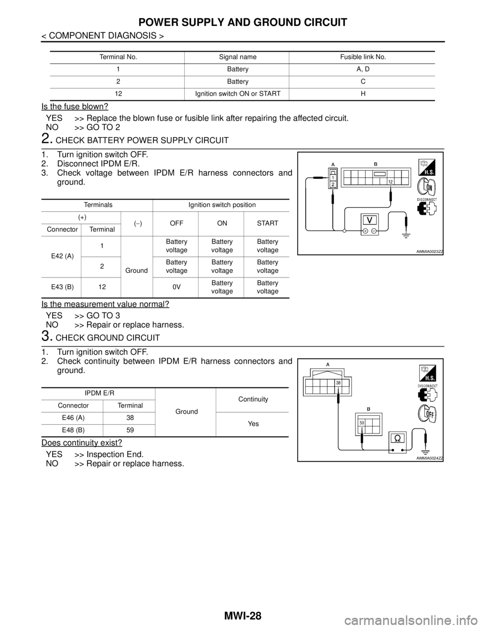
2. CHECK BATTERY POWER SUPPLY CIRCUIT
1. Turn ignition switch OFF.
2. Disconnect IPDM E/R.
3. Check voltage between IPDM E/R harness connectors and
ground.
Is the measurement value normal?
YES >> GO TO 3
NO >> Repair or replace harness.
3. CHECK GROUND CIRCUIT
1. Turn ignition switch OFF.
2. Check continuity between IPDM E/R harness connectors and
ground.
Does continuity exist?
YES >> Inspection End.
NO >> Repair or replace harness.
Terminal No. Signal name Fusible link No.
1 Battery A, D
2 Battery C
12 Ignition switch ON or START H
Terminals Ignition switch position
(+)
(−) OFF ON START
Connector Terminal
E42 (A)1
GroundBattery
voltageBattery
voltageBattery
voltage
2Battery
voltageBattery
voltageBattery
voltage
E43 (B) 12 0VBattery
voltageBattery
voltage
AWMIA0023ZZ
IPDM E/R
GroundContinuity
Connector Terminal
E46 (A) 38
Ye s
E48 (B) 59
AWMIA0024ZZ
Page 4336 of 5883
MWI
FUEL LEVEL SENSOR SIGNAL CIRCUIT
MWI-29
< COMPONENT DIAGNOSIS >
C
D
E
F
G
H
I
J
K
L
MB A
O
P
FUEL LEVEL SENSOR SIGNAL CIRCUIT
DescriptionINFOID:0000000001374693
The fuel level sensor unit and fuel pump detects the approximate fuel level in the fuel tank and transmits the
fuel level signal to the combination meter.
Component Function CheckINFOID:0000000001374694
1.COMBINATION METER INPUT SIGNAL
1. Select “METER/M&A” on CONSULT-III.
2. Using “FUEL METER” of “DATA MONITOR”, compare the value of DATA MONITOR with fuel gauge
pointer of combination meter.
Does the data monitor value approximately match the fuel gauge indication?
YES >> Inspection End.
NO >> Replace combination meter. Refer to MWI-94, "
Removal and Installation".
Diagnosis ProcedureINFOID:0000000001374695
1.CHECK HARNESS CONNECTOR
1. Turn ignition switch OFF.
2. Check combination meter and fuel level sensor unit terminals (meter-side and harness-side) for poor con-
nection.
Is the inspection result normal?
YES >> GO TO 2
NO >> Repair or replace terminals or connectors.
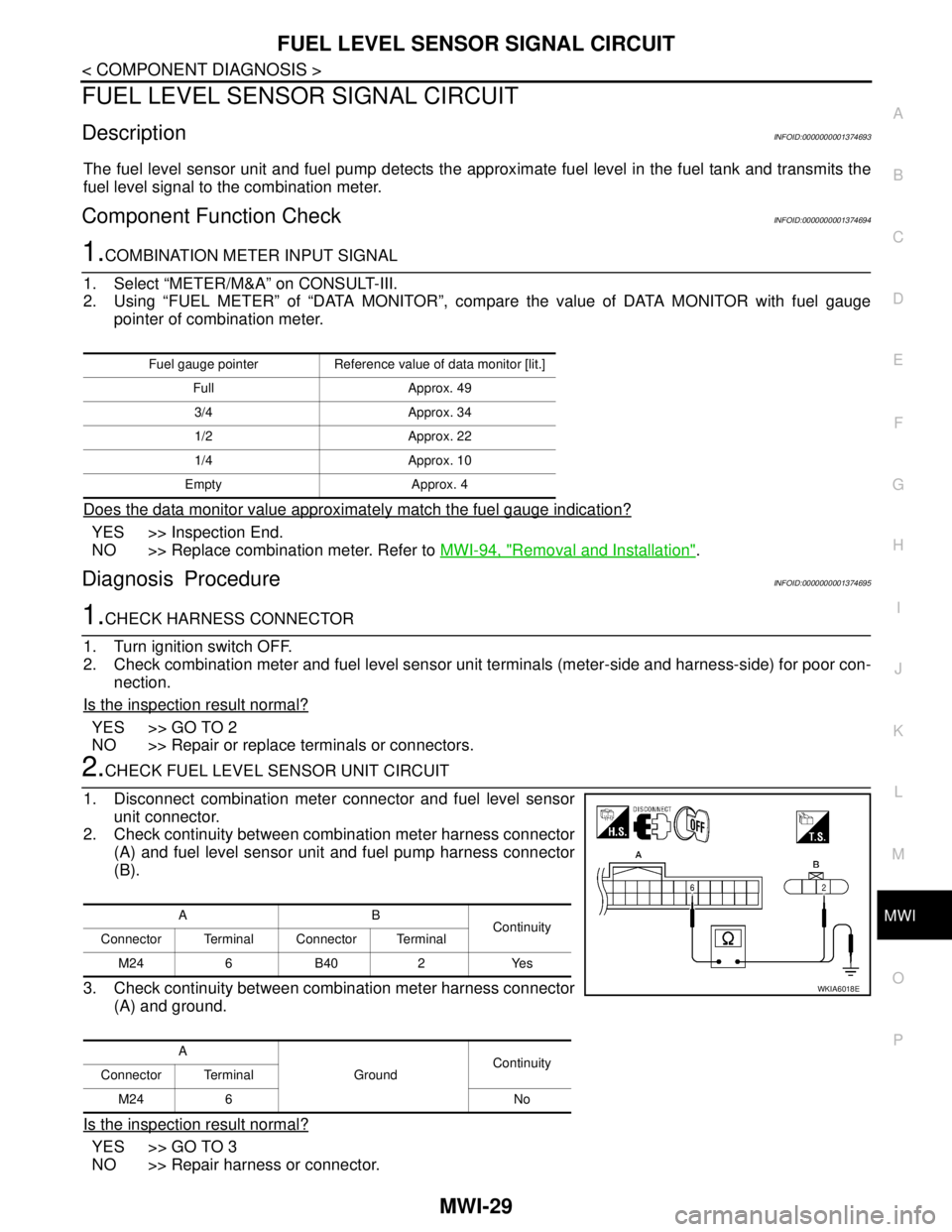
2.CHECK FUEL LEVEL SENSOR UNIT CIRCUIT
1. Disconnect combination meter connector and fuel level sensor
unit connector.
2. Check continuity between combination meter harness connector
(A) and fuel level sensor unit and fuel pump harness connector
(B).
3. Check continuity between combination meter harness connector
(A) and ground.
Is the inspection result normal?
YES >> GO TO 3
NO >> Repair harness or connector.
Fuel gauge pointer Reference value of data monitor [lit.]
Full Approx. 49
3/4 Approx. 34
1/2 Approx. 22
1/4 Approx. 10
Empty Approx. 4
AB
Continuity
Connector Terminal Connector Terminal
M24 6 B40 2 Yes
A
GroundContinuity
Connector Terminal
M24 6 No
WKIA6018E
Page 4337 of 5883
MWI-30
< COMPONENT DIAGNOSIS >
FUEL LEVEL SENSOR SIGNAL CIRCUIT
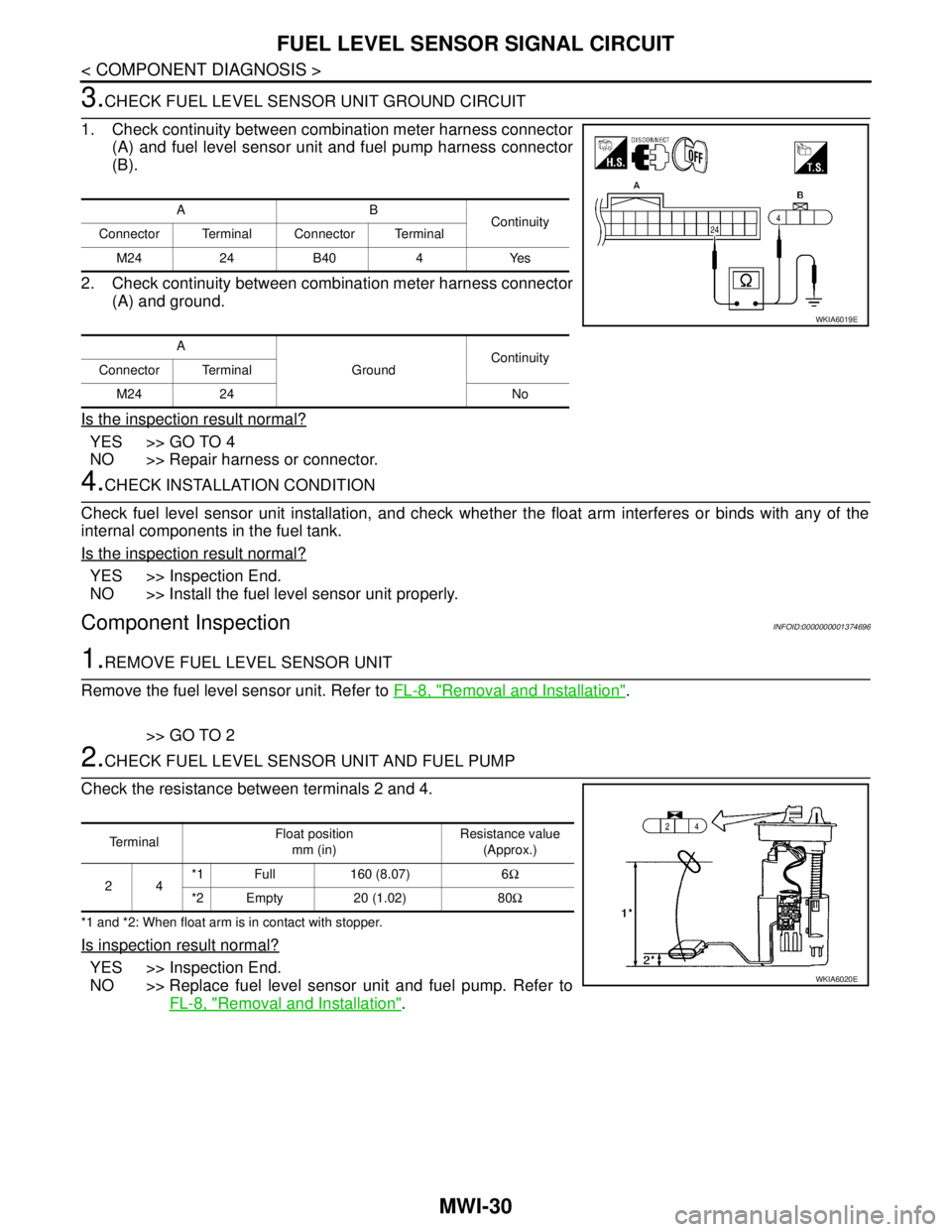
3.CHECK FUEL LEVEL SENSOR UNIT GROUND CIRCUIT
1. Check continuity between combination meter harness connector
(A) and fuel level sensor unit and fuel pump harness connector
(B).
2. Check continuity between combination meter harness connector
(A) and ground.
Is the inspection result normal?
YES >> GO TO 4
NO >> Repair harness or connector.
4.CHECK INSTALLATION CONDITION
Check fuel level sensor unit installation, and check whether the float arm interferes or binds with any of the
internal components in the fuel tank.
Is the inspection result normal?
YES >> Inspection End.
NO >> Install the fuel level sensor unit properly.
Component InspectionINFOID:0000000001374696
1.REMOVE FUEL LEVEL SENSOR UNIT
Remove the fuel level sensor unit. Refer to FL-8, "
Removal and Installation".
>> GO TO 2
2.CHECK FUEL LEVEL SENSOR UNIT AND FUEL PUMP
Check the resistance between terminals 2 and 4.
*1 and *2: When float arm is in contact with stopper.
Is inspection result normal?
YES >> Inspection End.
NO >> Replace fuel level sensor unit and fuel pump. Refer to
FL-8, "
Removal and Installation".
AB
Continuity
Connector Terminal Connector Terminal
M24 24 B40 4 Yes
A
GroundContinuity
Connector Terminal
M24 24 No
WKIA6019E
Te r m i n a lFloat position
mm (in)Resistance value
(Approx.)
24*1 Full 160 (8.07) 6Ω
*2 Empty 20 (1.02) 80Ω
WKIA6020E
Page 4338 of 5883
MWI
OIL PRESSURE SWITCH SIGNAL CIRCUIT
MWI-31
< COMPONENT DIAGNOSIS >
C
D
E
F
G
H
I
J
K
L
MB A
O
P
OIL PRESSURE SWITCH SIGNAL CIRCUIT
DescriptionINFOID:0000000001374697
Detects the engine oil pressure and transmits the oil pressure switch signal to the IPDM E/R.
Component Function CheckINFOID:0000000001374698
1.COMBINATION METER INPUT SIGNAL
1. Select “METER/M&A” on CONSULT-III.
2. Monitor “OIL W/L” of “DATA MONITOR” while operating ignition switch.
>> Inspection End.
Diagnosis ProcedureINFOID:0000000001374699
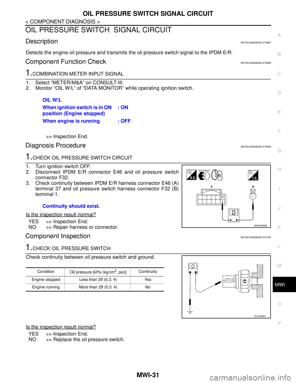
1.CHECK OIL PRESSURE SWITCH CIRCUIT
1. Turn ignition switch OFF.
2. Disconnect IPDM E/R connector E46 and oil pressure switch
connector F32.
3. Check continuity between IPDM E/R harness connector E46 (A)
terminal 37 and oil pressure switch harness connector F32 (B)
terminal 1.
Is the inspection result normal?
YES >> Inspection End.
NO >> Repair harness or connector.
Component InspectionINFOID:0000000001374700
1.CHECK OIL PRESSURE SWITCH
Check continuity between oil pressure switch and ground.
Is the inspection result normal?
YES >> Inspection End.
NO >> Replace the oil pressure switch.OIL W/L
When ignition switch is in ON
position (Engine stopped): ON
When engine is running : OFF
Continuity should exist.
WKIA5459E
Condition
Oil pressure [kPa (kg/cm2, psi)]Continuity
Engine stopped Less than 29 (0.3, 4) Yes
Engine running More than 29 (0.3, 4) No
ELF0044D
Page 4339 of 5883
MWI-32
< COMPONENT DIAGNOSIS >
OIL LEVEL SENSOR SIGNAL CIRCUIT
OIL LEVEL SENSOR SIGNAL CIRCUIT
DescriptionINFOID:0000000001537460
Transmits the oil level sensor signal to the combination meter.
Diagnosis Procedure (With Diesel)INFOID:0000000001537463
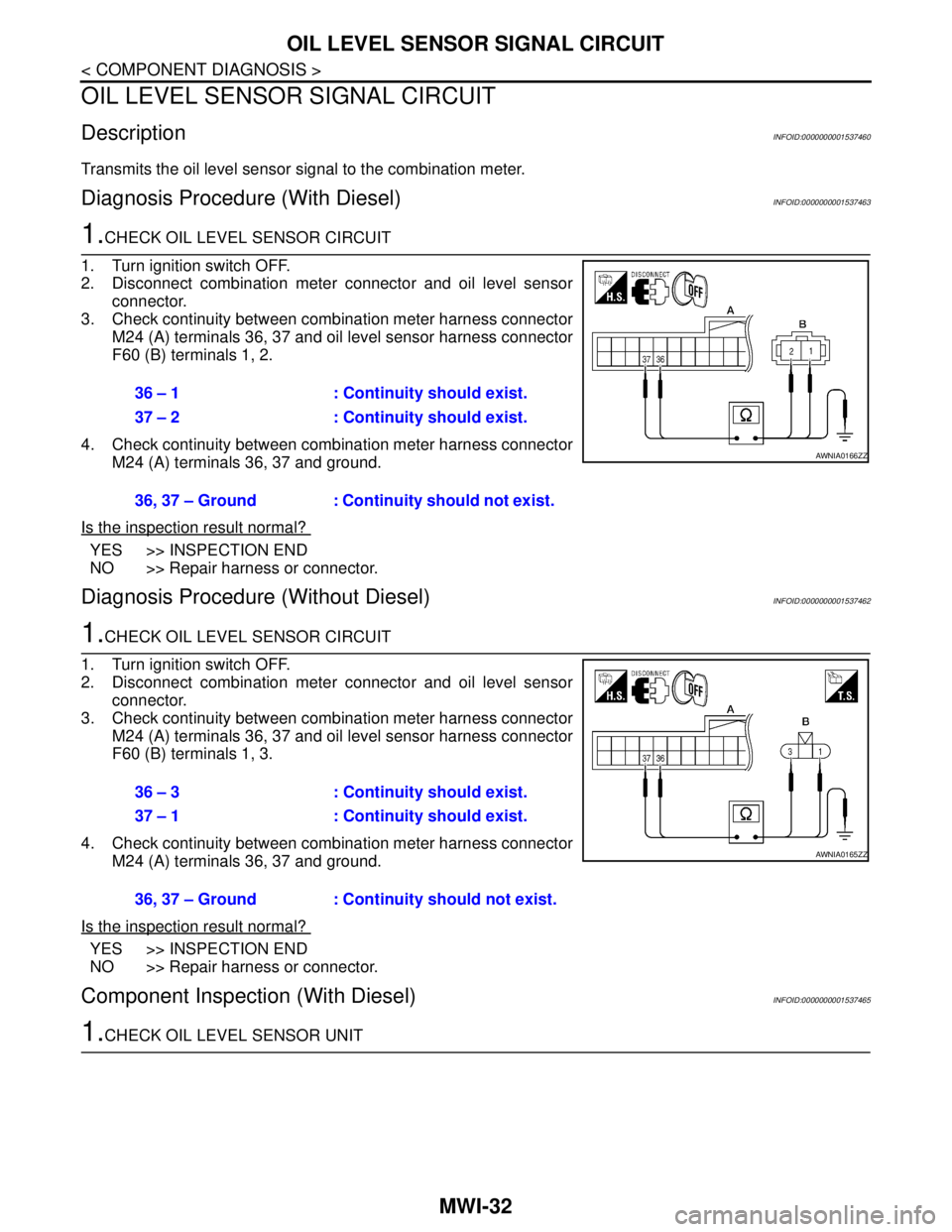
1.CHECK OIL LEVEL SENSOR CIRCUIT
1. Turn ignition switch OFF.
2. Disconnect combination meter connector and oil level sensor
connector.
3. Check continuity between combination meter harness connector
M24 (A) terminals 36, 37 and oil level sensor harness connector
F60 (B) terminals 1, 2.
4. Check continuity between combination meter harness connector
M24 (A) terminals 36, 37 and ground.
Is the inspection result normal?
YES >> INSPECTION END
NO >> Repair harness or connector.
Diagnosis Procedure (Without Diesel)INFOID:0000000001537462
1.CHECK OIL LEVEL SENSOR CIRCUIT
1. Turn ignition switch OFF.
2. Disconnect combination meter connector and oil level sensor
connector.
3. Check continuity between combination meter harness connector
M24 (A) terminals 36, 37 and oil level sensor harness connector
F60 (B) terminals 1, 3.
4. Check continuity between combination meter harness connector
M24 (A) terminals 36, 37 and ground.
Is the inspection result normal?
YES >> INSPECTION END
NO >> Repair harness or connector.
Component Inspection (With Diesel)INFOID:0000000001537465
1.CHECK OIL LEVEL SENSOR UNIT36 – 1 : Continuity should exist.
37 – 2 : Continuity should exist.
36, 37 – Ground : Continuity should not exist.
AWNIA0166ZZ
36 – 3 : Continuity should exist.
37 – 1 : Continuity should exist.
36, 37 – Ground : Continuity should not exist.
AWNIA0165ZZ
Page 4340 of 5883
MWI
OIL LEVEL SENSOR SIGNAL CIRCUIT
MWI-33
< COMPONENT DIAGNOSIS >
C
D
E
F
G
H
I
J
K
L
MB A
O
P
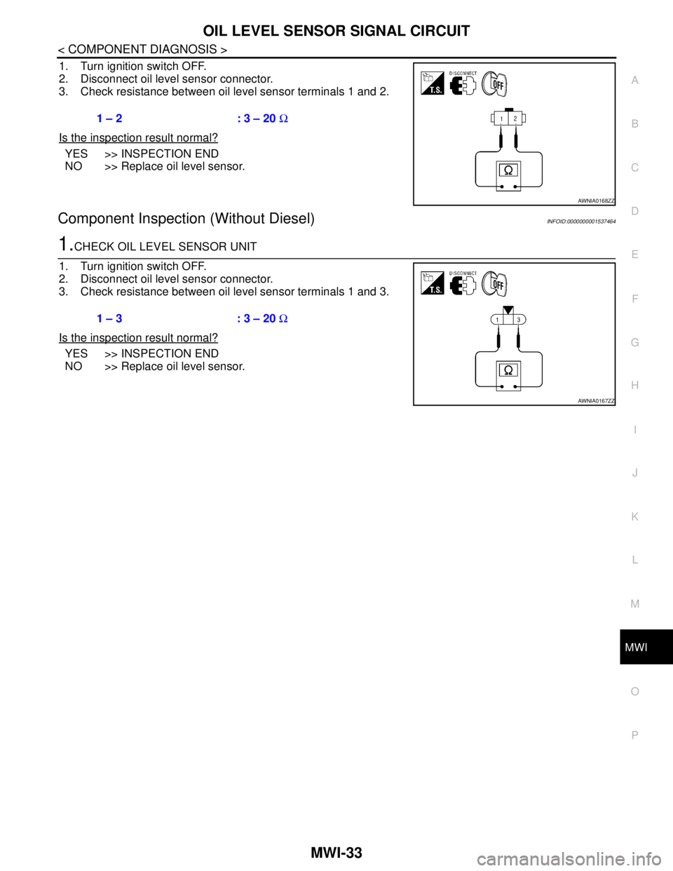
1. Turn ignition switch OFF.
2. Disconnect oil level sensor connector.
3. Check resistance between oil level sensor terminals 1 and 2.
Is the inspection result normal?
YES >> INSPECTION END
NO >> Replace oil level sensor.
Component Inspection (Without Diesel)INFOID:0000000001537464
1.CHECK OIL LEVEL SENSOR UNIT
1. Turn ignition switch OFF.
2. Disconnect oil level sensor connector.
3. Check resistance between oil level sensor terminals 1 and 3.
Is the inspection result normal?
YES >> INSPECTION END
NO >> Replace oil level sensor.1 – 2 : 3 – 20 Ω
AWNIA0168ZZ
1 – 3 : 3 – 20 Ω
AWNIA0167ZZ