NISSAN TIIDA 2007 Service Repair Manual
Manufacturer: NISSAN, Model Year: 2007, Model line: TIIDA, Model: NISSAN TIIDA 2007Pages: 5883, PDF Size: 78.95 MB
Page 461 of 5883
![NISSAN TIIDA 2007 Service Repair Manual CHG-40
< COMPONENT DIAGNOSIS >[K9K]
S TERMINAL CIRCUIT
S TERMINAL CIRCUIT
DescriptionINFOID:0000000001724513
The output voltage of the generator is controlled by the IC regulator at terminal “3” ( NISSAN TIIDA 2007 Service Repair Manual CHG-40
< COMPONENT DIAGNOSIS >[K9K]
S TERMINAL CIRCUIT
S TERMINAL CIRCUIT
DescriptionINFOID:0000000001724513
The output voltage of the generator is controlled by the IC regulator at terminal “3” (](/img/5/57395/w960_57395-460.png)
CHG-40
< COMPONENT DIAGNOSIS >[K9K]
S TERMINAL CIRCUIT
S TERMINAL CIRCUIT
DescriptionINFOID:0000000001724513
The output voltage of the generator is controlled by the IC regulator at terminal “3” (S) detecting the input volt-
age. Terminal “3” circuit detects the battery voltage to adjust the generator output voltage with the IC regulator.
Diagnosis ProcedureINFOID:0000000001724514
1.CHECK VOLTAGE REGULATOR CIRCUIT CONNECTION
Check to see if connector F1 terminal 3 is clean and tight.
Is the inspection result normal?
YES >> GO TO 2
NO >> Repair terminal connection. Confirm repair by performing complete Starting/Charging system test.
Refer to Technical Service Bulletin.
2.CHECK VOLTAGE REGULATOR CIRCUIT
1. Disconnect generator harness connector F1.
2. Turn ignition switch ON.
3. Check voltage between generator harness connector F1 termi-
nal 3 and ground.
Does battery voltage exist?
YES >> Refer to CHG-33, "Work Flow".
NO >> Check harness for open between generator and fuse.3 - ground Battery voltage
ALMIA0330GB
Page 462 of 5883
![NISSAN TIIDA 2007 Service Repair Manual CHG
CHARGING SYSTEM
CHG-41
< COMPONENT DIAGNOSIS >[K9K]
C
D
E
F
G
H
I
J
K
L B A
O
P N
CHARGING SYSTEM
Wiring DiagramINFOID:0000000001724515
AWMWA0023GB NISSAN TIIDA 2007 Service Repair Manual CHG
CHARGING SYSTEM
CHG-41
< COMPONENT DIAGNOSIS >[K9K]
C
D
E
F
G
H
I
J
K
L B A
O
P N
CHARGING SYSTEM
Wiring DiagramINFOID:0000000001724515
AWMWA0023GB](/img/5/57395/w960_57395-461.png)
CHG
CHARGING SYSTEM
CHG-41
< COMPONENT DIAGNOSIS >[K9K]
C
D
E
F
G
H
I
J
K
L B A
O
P N
CHARGING SYSTEM
Wiring DiagramINFOID:0000000001724515
AWMWA0023GB
Page 463 of 5883
![NISSAN TIIDA 2007 Service Repair Manual CHG-42
< SYMPTOM DIAGNOSIS >[K9K]
CHARGING SYSTEM
SYMPTOM DIAGNOSIS
CHARGING SYSTEM
Symptom TableINFOID:0000000001724516
Symptom Reference
Battery discharged
Refer to CHG-33, "
Work Flow". The charge NISSAN TIIDA 2007 Service Repair Manual CHG-42
< SYMPTOM DIAGNOSIS >[K9K]
CHARGING SYSTEM
SYMPTOM DIAGNOSIS
CHARGING SYSTEM
Symptom TableINFOID:0000000001724516
Symptom Reference
Battery discharged
Refer to CHG-33, "
Work Flow". The charge](/img/5/57395/w960_57395-462.png)
CHG-42
< SYMPTOM DIAGNOSIS >[K9K]
CHARGING SYSTEM
SYMPTOM DIAGNOSIS
CHARGING SYSTEM
Symptom TableINFOID:0000000001724516
Symptom Reference
Battery discharged
Refer to CHG-33, "
Work Flow". The charge warning lamp does not illuminate when the ignition
switch is set to ON.
The charge warning lamp does not turn OFF after the engine
starts.
The charging warning lamp turns ON when increasing the engine
speed.
Page 464 of 5883
![NISSAN TIIDA 2007 Service Repair Manual CHG
GENERATOR
CHG-43
< ON-VEHICLE REPAIR >[K9K]
C
D
E
F
G
H
I
J
K
L B A
O
P N
ON-VEHICLE REPAIR
GENERATOR
Removal and InstallationINFOID:0000000001689502
REMOVAL
1. Disconnect the battery cable from t NISSAN TIIDA 2007 Service Repair Manual CHG
GENERATOR
CHG-43
< ON-VEHICLE REPAIR >[K9K]
C
D
E
F
G
H
I
J
K
L B A
O
P N
ON-VEHICLE REPAIR
GENERATOR
Removal and InstallationINFOID:0000000001689502
REMOVAL
1. Disconnect the battery cable from t](/img/5/57395/w960_57395-463.png)
CHG
GENERATOR
CHG-43
< ON-VEHICLE REPAIR >[K9K]
C
D
E
F
G
H
I
J
K
L B A
O
P N
ON-VEHICLE REPAIR
GENERATOR
Removal and InstallationINFOID:0000000001689502
REMOVAL
1. Disconnect the battery cable from the negative terminal.
2. Remove RH fender protector partially.
3. Remove fuel injection pipe protector.
4. Remove drive belt. Refer to EM-263, "
Removal and Installation".
5. Disconnect generator connector.
6. Remove “B” terminal nut and “B” terminal harness.
7. Remove upper generator bolt.
8. Release lower generator bolt, then push it aside.
9. Remove generator with lower bolt.
NOTE:
Pull generator to the front side from upside. Turn, then pull lower side of generator with lower bolt.
INSTALLATION
Installation is in the reverse order of removal.
CAUTION:
Be sure to tighten “B” terminal nut carefully.
Install generator, and check tension of belt. Refer to EM-263, "
Inspection and Adjustment".
1. Generator connector 2. Generator bolt 3. Generator
4. “B” terminal harness 5. “B” terminal nut
JPMIA0263GB
Page 465 of 5883
![NISSAN TIIDA 2007 Service Repair Manual CHG-44
< SERVICE DATA AND SPECIFICATIONS (SDS) [K9K]
SERVICE DATA AND SPECIFICATIONS (SDS)
SERVICE DATA AND SPECIFICATIONS (SDS)
SERVICE DATA AND SPECIFICATIONS (SDS)
GeneratorINFOID:0000000001691231
NISSAN TIIDA 2007 Service Repair Manual CHG-44
< SERVICE DATA AND SPECIFICATIONS (SDS) [K9K]
SERVICE DATA AND SPECIFICATIONS (SDS)
SERVICE DATA AND SPECIFICATIONS (SDS)
SERVICE DATA AND SPECIFICATIONS (SDS)
GeneratorINFOID:0000000001691231](/img/5/57395/w960_57395-464.png)
CHG-44
< SERVICE DATA AND SPECIFICATIONS (SDS) [K9K]
SERVICE DATA AND SPECIFICATIONS (SDS)
SERVICE DATA AND SPECIFICATIONS (SDS)
SERVICE DATA AND SPECIFICATIONS (SDS)
GeneratorINFOID:0000000001691231
Applied modelK9K
Ty p e0 124 525 082
BOSCH make
Nominal rating [V - A] —
Ground polarity—
Minimum revolution under no-load (When 13.5 V
is applied)[rpm] —
Hot output current (When 13.5 V is applied) [A/rpm] —
Regulated output voltage [V] —
Minimum length of brush [mm (in)] —
Brush spring pressure [N (g, oz)] —
Slip ring minimum outer diameter [mm (in)] —
Rotor (Field coil) resistance [Ω]—
Page 466 of 5883
CL-1
TRANSMISSION & DRIVELINE
C
E
F
G
H
I
J
K
L
M
SECTION CL
A
B
CL
N
O
P
CONTENTS
CLUTCH
SERVICE INFORMATION ............................2
PRECAUTIONS ...................................................2
Precaution for Supplemental Restraint System
(SRS) "AIR BAG" and "SEAT BELT PRE-TEN-
SIONER" ...................................................................
2
Service Notice or Precaution .....................................2
PREPARATION ...................................................3
Special Service Tool .................................................3
Commercial Service Tool ..........................................3
NOISE, VIBRATION AND HARSHNESS
(NVH) TROUBLESHOOTING .............................
4
NVH Troubleshooting Chart ......................................4
CLUTCH PEDAL .................................................5
On-vehicle Inspection and Adjustment ......................5
Removal and Installation ...........................................6
CLUTCH FLUID ...................................................8
Air Bleeding Procedure .............................................8
CLUTCH MASTER CYLINDER .........................9
Removal and Installation ..........................................9
CSC (CONCENTRIC SLAVE CYLINDER) .......11
Removal and Installation .........................................11
CLUTCH PIPING ...............................................12
Removal and Installation .........................................12
CLUTCH DISC, CLUTCH COVER AND FLY-
WHEEL ..............................................................
13
Removal and Installation .........................................13
SERVICE DATA AND SPECIFICATIONS
(SDS) .................................................................
16
Clutch Control System .............................................16
Clutch Pedal ............................................................16
Clutch Disc ..............................................................16
Clutch Cover ............................................................16
Page 467 of 5883
CL-2
< SERVICE INFORMATION >
PRECAUTIONS
SERVICE INFORMATION
PRECAUTIONS
Precaution for Supplemental Restraint System (SRS) "AIR BAG" and "SEAT BELT
PRE-TENSIONER"
INFOID:0000000001375288
The Supplemental Restraint System such as “AIR BAG” and “SEAT BELT PRE-TENSIONER”, used along
with a front seat belt, helps to reduce the risk or severity of injury to the driver and front passenger for certain
types of collision. This system includes seat belt switch inputs and dual stage front air bag modules. The SRS
system uses the seat belt switches to determine the front air bag deployment, and may only deploy one front
air bag, depending on the severity of a collision and whether the front occupants are belted or unbelted.
Information necessary to service the system safely is included in the SRS and SB section of this Service Man-
ual.
WARNING:
• To avoid rendering the SRS inoperative, which could increase the risk of personal injury or death in
the event of a collision which would result in air bag inflation, all maintenance must be performed by
an authorized NISSAN/INFINITI dealer.
Improper maintenance, including incorrect removal and installation of the SRS, can lead to personal
injury caused by unintentional activation of the system. For removal of Spiral Cable and Air Bag
Module, see the SRS section.
Do not use electrical test equipment on any circuit related to the SRS unless instructed to in this
Service Manual. SRS wiring harnesses can be identified by yellow and/or orange harnesses or har-
ness connectors.
Service Notice or PrecautionINFOID:0000000001375289
Use recommended brake fluid when adding fluid to the clutch reservoir tank. Refer to MA-19, "Fluids
and Lubricants".
Do not reuse fluid drained from clutch system.
Do not splash brake fluid on painted areas.
Use new brake fluid to clean or wash all parts of master cylinder and operating cylinder.
Do not use mineral oils such as gasoline or kerosene. It will ruin the rubber parts of the hydraulic
system.
If transaxle assembly is removed from the vehicle, always replace CSC (Concentric slave cylinder).
Return CSC to original position to remove transaxle assembly. Dust on clutch disc sliding parts may
damage CSC seal and may cause clutch fluid leakage.
Do not disassemble clutch master cylinder and CSC.
WARNING:
After cleaning clutch disc, clean it with a dust collector. Do not use compressed air.
Page 468 of 5883
PREPARATION
CL-3
< SERVICE INFORMATION >
C
E
F
G
H
I
J
K
L
MA
B
CL
N
O
P
PREPARATION
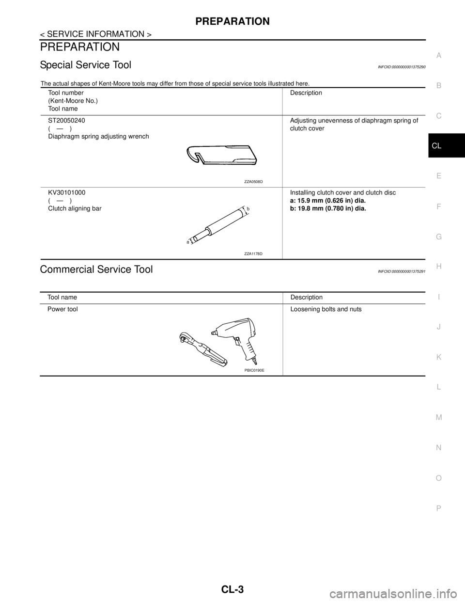
Special Service ToolINFOID:0000000001375290
The actual shapes of Kent-Moore tools may differ from those of special service tools illustrated here.
Commercial Service ToolINFOID:0000000001375291
Tool number
(Kent-Moore No.)
Tool nameDescription
ST20050240
(—)
Diaphragm spring adjusting wrenchAdjusting unevenness of diaphragm spring of
clutch cover
KV30101000
(—)
Clutch aligning barInstalling clutch cover and clutch disc
a: 15.9 mm (0.626 in) dia.
b: 19.8 mm (0.780 in) dia.
ZZA0508D
ZZA1178D
Tool nameDescription
Power toolLoosening bolts and nuts
PBIC0190E
Page 469 of 5883
CL-4
< SERVICE INFORMATION >
NOISE, VIBRATION AND HARSHNESS (NVH) TROUBLESHOOTING
NOISE, VIBRATION AND HARSHNESS (NVH) TROUBLESHOOTING
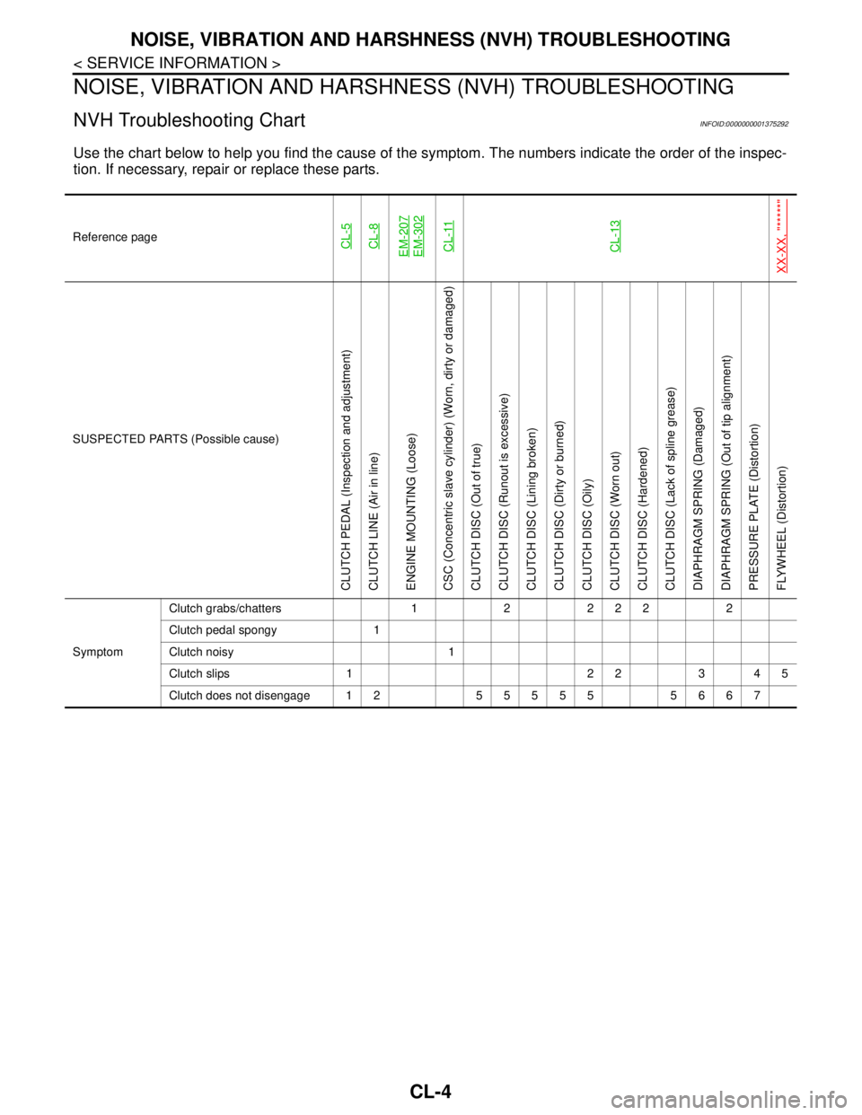
NVH Troubleshooting ChartINFOID:0000000001375292
Use the chart below to help you find the cause of the symptom. The numbers indicate the order of the inspec-
tion. If necessary, repair or replace these parts.
Reference pageCL-5CL-8EM-207EM-302CL-11CL-13
XX-XX, "*****"
SUSPECTED PARTS (Possible cause)
CLUTCH PEDAL (Inspection and adjustment)
CLUTCH LINE (Air in line)
ENGINE MOUNTING (Loose)
CSC (Concentric slave cylinder) (Worn, dirty or damaged)
CLUTCH DISC (Out of true)
CLUTCH DISC (Runout is excessive)
CLUTCH DISC (Lining broken)
CLUTCH DISC (Dirty or burned)
CLUTCH DISC (Oily)
CLUTCH DISC (Worn out)
CLUTCH DISC (Hardened)
CLUTCH DISC (Lack of spline grease)
DIAPHRAGM SPRING (Damaged)
DIAPHRAGM SPRING (Out of tip alignment)
PRESSURE PLATE (Distortion)
FLYWHEEL (Distortion)
SymptomClutch grabs/chatters 1 2 2 2 2 2
Clutch pedal spongy 1
Clutch noisy 1
Clutch slips 1 2 2 3 4 5
Clutch does not disengage 12 55555 5667
Page 470 of 5883
CLUTCH PEDAL
CL-5
< SERVICE INFORMATION >
C
E
F
G
H
I
J
K
L
MA
B
CL
N
O
P
CLUTCH PEDAL
On-vehicle Inspection and AdjustmentINFOID:0000000001375293
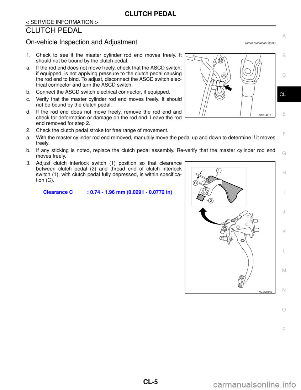
1. Check to see if the master cylinder rod end moves freely. It
should not be bound by the clutch pedal.
a. If the rod end does not move freely, check that the ASCD switch,
if equipped, is not applying pressure to the clutch pedal causing
the rod end to bind. To adjust, disconnect the ASCD switch elec-
trical connector and turn the ASCD switch.
b. Connect the ASCD switch electrical connector, if equipped.
c. Verify that the master cylinder rod end moves freely. It should
not be bound by the clutch pedal.
d. If the rod end does not move freely, remove the rod end and
check for deformation or damage on the rod end. Leave the rod
end removed for step 2.
2. Check the clutch pedal stroke for free range of movement.
a. With the master cylinder rod end removed, manually move the pedal up and down to determine if it moves
freely.
b. If any sticking is noted, replace the clutch pedal assembly. Re-verify that the master cylinder rod end
moves freely.
3. Adjust clutch interlock switch (1) position so that clearance
between clutch pedal (2) and thread end of clutch interlock
switch (1), with clutch pedal fully depressed, is within specifica-
tion (C).
Clearance C : 0.74 - 1.96 mm (0.0291 - 0.0772 in)
PCIB1491E
WCIA0594E