NISSAN X-TRAIL 2003 Electronic User Guide
Manufacturer: NISSAN, Model Year: 2003, Model line: X-TRAIL, Model: NISSAN X-TRAIL 2003Pages: 3066, PDF Size: 51.47 MB
Page 11 of 3066

PRECAUTIONS
AT-5
D
E
F
G
H
I
J
K
L
MA
B
AT
PRECAUTIONSPFP:00001
Precautions for Supplemental Restraint System (SRS) “AIR BAG” and “SEAT
BELT PRE-TENSIONER”
ECS004Q0
The Supplemental Restraint System such as “AIR BAG” and “SEAT BELT PRE-TENSIONER”, used along
with a front seat belt, helps to reduce the risk or severity of injury to the driver and front passenger for certain
types of collision. Information necessary to service the system safely is included in the SRS and SB section of
this Service Manual.
WA RN ING:
lTo avoid rendering the SRS inoperative, which could increase the risk of personal injury or death
in the event of a collision which would result in air bag inflation, all maintenance must be per-
formed by an authorized NISSAN/INFINITI dealer.
lImproper maintenance, including incorrect removal and installation of the SRS, can lead to per-
sonal injury caused by unintentional activation of the system. For removal of Spiral Cable and Air
Bag Module, see the SRS section.
lDo not use electrical test equipment on any circuit related to the SRS unless instructed to in this
Service Manual. SRS wiring harnesses can be identified by yellow harness connectors.
Precautions for On Board Diagnostic (EURO-OBD) System of A/T and Engine —
Euro-OBD —
ECS004Q1
The ECM has an on board diagnostic system. It will light up the malfunction indicator lamp (MIL) to warn the
driver of a malfunction causing emission deterioration.
CAUTION:
lBe sure to turn the ignition switch “OFF” and disconnect the negative battery terminal before any
repair or inspection work. The open/short circuit of related switches, sensors, solenoid valves,
etc. will cause the MIL to light up.
lBe sure to connect and lock the connectors securely after work. A loose (unlocked) connector will
cause the MIL to light up due to an open circuit. (Be sure the connector is free from water, grease,
dirt, bent terminals, etc.)
lBe sure to route and secure the harnesses properly after work. Interference of the harness with a
bracket, etc. may cause the MIL to light up due to a short circuit.
lBe sure to connect rubber tubes properly after work. A misconnected or disconnected rubber tube
may cause the MIL to light up due to a malfunction of the EGR system or fuel injection system, etc.
lBe sure to erase the unnecessary malfunction information (repairs completed) from the TCM and
ECM before returning the vehicle to the customer.
Precautions For Trouble DiagnosisECS004VN
CAN SYSTEM
lDo not apply voltage of 7.0V or higher to the measurement terminals.
lUse the tester with its open terminal voltage being 7.0V or less.
Precautions For Harness RepairECS004VO
CAN SYSTEM
lSolder the repaired parts, and wrap with tape. [Frays of twisted
line must be within 110 mm (4.33 in)]
PKIA0306E
Page 12 of 3066

AT-6
PRECAUTIONS
lDo not perform bypass wire connections for the repair
parts.(The spliced wire will become separated and the charac-
teristics of twisted line will be lost.)
PrecautionsECS004Q2
lBefore connecting or disconnecting the TCM harness con-
nector, turn ignition switch OFF and disconnect negative
battery terminal. Failure to do so may damage the TCM.
Because battery voltage is applied to TCM even if ignition
switch is turned off.
lWhen connecting or disconnecting pin connectors into or
from TCM, take care not to damage pin terminals (bend or
break).
Make sure that there are not any bends or breaks on TCM
pin terminal, when connecting pin connectors.
lBefore replacing TCM, perform TCM input/output signal
inspection and make sure whether TCM functions properly
or not. (See pageAT- 1 2 5 , "
TCM Terminals and Reference
Va l u e".)
PKIA0307E
SEF289H
AAT470A
MEF040DA
Page 13 of 3066
PRECAUTIONS
AT-7
D
E
F
G
H
I
J
K
L
MA
B
AT
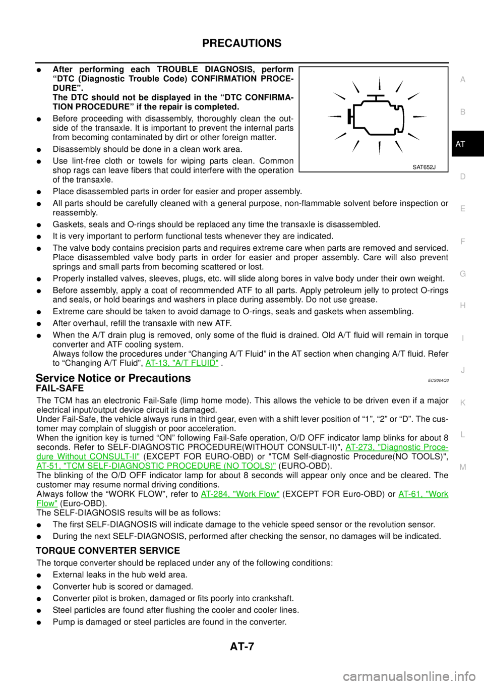
lAfter performing each TROUBLE DIAGNOSIS, perform
“DTC (Diagnostic Trouble Code) CONFIRMATION PROCE-
DURE”.
The DTC should not be displayed in the “DTC CONFIRMA-
TION PROCEDURE” if the repair is completed.
lBefore proceeding with disassembly, thoroughly clean the out-
side of the transaxle. It is important to prevent the internal parts
from becoming contaminated by dirt or other foreign matter.
lDisassembly should be done in a clean work area.
lUse lint-free cloth or towels for wiping parts clean. Common
shop rags can leave fibers that could interfere with the operation
of the transaxle.
lPlace disassembled parts in order for easier and proper assembly.
lAll parts should be carefully cleaned with a general purpose, non-flammable solvent before inspection or
reassembly.
lGaskets, seals and O-rings should be replaced any time the transaxle is disassembled.
lIt is very important to perform functional tests whenever they are indicated.
lThe valve body contains precision parts and requires extreme care when parts are removed and serviced.
Place disassembled valve body parts in order for easier and proper assembly. Care will also prevent
springs and small parts from becoming scattered or lost.
lProperly installed valves, sleeves, plugs, etc. will slide along bores in valve body under their own weight.
lBefore assembly, apply a coat of recommended ATF to all parts. Apply petroleum jelly to protect O-rings
and seals, or hold bearings and washers in place during assembly. Do not use grease.
lExtreme care should be taken to avoid damage to O-rings, seals and gaskets when assembling.
lAfter overhaul, refill the transaxle with new ATF.
lWhen the A/T drain plug is removed, only some of the fluid is drained. Old A/T fluid will remain in torque
converter and ATF cooling system.
Always follow the procedures under “Changing A/T Fluid” in the AT section when changing A/T fluid. Refer
to “Changing A/T Fluid”,AT-13, "
A/T FLUID".
Service Notice or PrecautionsECS004Q3
FAI L-S AFE
The TCM has an electronic Fail-Safe (limp home mode). This allows the vehicle to be driven even if a major
electrical input/output device circuit is damaged.
Under Fail-Safe, the vehicle always runs in third gear, even with a shift lever position of “1”, “2” or “D”. The cus-
tomer may complain of sluggish or poor acceleration.
When the ignition key is turned “ON” following Fail-Safe operation, O/D OFF indicator lamp blinks for about 8
seconds. Refer to SELF-DIAGNOSTIC PROCEDURE(WITHOUT CONSULT-II)",AT- 2 7 3 , "
Diagnostic Proce-
dure Without CONSULT-II"(EXCEPT FOR EURO-OBD) or "TCM Self-diagnostic Procedure(NO TOOLS)",
AT- 5 1 , "
TCM SELF-DIAGNOSTIC PROCEDURE (NO TOOLS)"(EURO-OBD).
The blinking of the O/D OFF indicator lamp for about 8 seconds will appear only once and be cleared. The
customer may resume normal driving conditions.
Always follow the “WORK FLOW”, refer toAT-284, "
Work Flow"(EXCEPT FOR Euro-OBD) orAT-61, "Work
Flow"(Euro-OBD).
The SELF-DIAGNOSIS results will be as follows:
lThe first SELF-DIAGNOSIS will indicate damage to the vehicle speed sensor or the revolution sensor.
lDuring the next SELF-DIAGNOSIS, performed after checking the sensor, no damages will be indicated.
TORQUE CONVERTER SERVICE
The torque converter should be replaced under any of the following conditions:
lExternal leaks in the hub weld area.
lConverter hub is scored or damaged.
lConverter pilot is broken, damaged or fits poorly into crankshaft.
lSteel particles are found after flushing the cooler and cooler lines.
lPump is damaged or steel particles are found in the converter.
SAT652J
Page 14 of 3066

AT-8
PRECAUTIONS
lVehicle has TCC shudder and/or no TCC apply. Replace only after all hydraulic and electrical diagnoses
have been made. (Converter clutch material may be glazed.)
lConverter is contaminated with engine coolant containing antifreeze.
lInternal failure of stator roller clutch.
lHeavy clutch debris due to overheating (blue converter).
lSteel particles or clutch lining material found in fluid filter or on magnet when no internal parts in unit are
worn or damaged — indicates that lining material came from converter.
The torque converter should not be replaced if:
lThe fluid has an odor, is discolored, and there is no evidence of metal or clutch facing particles.
lThe threads in one or more of the converter bolt holes are damaged.
lTransaxle failure did not display evidence of damaged or worn internal parts, steel particles or clutch plate
lining material in unit and inside the fluid filter.
lVehicle has been exposed to high mileage (only). The exception may be where the torque converter
clutch dampener plate lining has seen excess wear by vehicles operated in heavy and/or constant traffic,
such as taxi, delivery or police use.
EURO-OBD SELF-DIAGNOSIS — EURO-OBD —
lA/T self-diagnosis is performed by the TCM in combination with the ECM. The results can be read through
the blinking pattern of the O/D OFF indicator lamp or the malfunction indicator lamp (MIL). Refer to the
table onAT-42, "
SELF-DIAGNOSTIC RESULT TEST MODE"for the indicator used to display each self-
diagnostic result.
lThe self-diagnostic results indicated by the MIL are automatically stored in both the ECM and TCM mem-
ories.
Always perform the procedure “HOW TO ERASE DTC” onAT-39, "
HOW TO ERASE DTC"to com-
plete the repair and avoid unnecessary blinking of the MIL.
lThe following self-diagnostic items can be detected using ECM self-diagnostic results mode* only when
the O/D OFF indicator lamp does not indicate any malfunctions.
–PNP switch
–A/T 1st, 2nd, 3rd, or 4th gear function
*: For details of EURO-OBD, refer toAT - 3 7 , "
ON BOARD DIAGNOSTIC SYSTEM DESCRIPTION".
lCertain systems and components, especially those related to EURO-OBD, may use a new style
slide-locking type harness connector.
For description and how to disconnect, refer toPG-70, "
HARNESS CONNECTOR".
Wiring Diagrams and Trouble DiagnosisECS004Q4
When you read wiring diagrams, refer to the following:
lGI-14, "How to Read Wiring Diagrams".
lPG-2, "POWER SUPPLY ROUTING".
When you perform trouble diagnosis, refer to the following:
lGI-11, "HOW TO FOLLOW TEST GROUPS IN TROUBLE DIAGNOSES".
l"", “HOW TO PERFORM EFFICIENT DIAGNOSIS FOR AN ELECTRICAL INCIDENT”
Page 15 of 3066
PREPARATION
AT-9
D
E
F
G
H
I
J
K
L
MA
B
AT
PREPARATIONPFP:00100
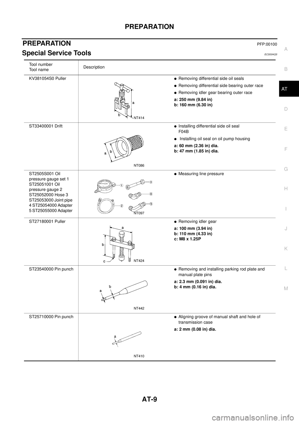
Special Service ToolsECS004Q5
Tool number
To o l n a m eDescription
KV381054S0 Puller
lRemoving differential side oil seals
lRemoving differential side bearing outer race
lRemoving idler gear bearing outer race
a: 250 mm (9.84 in)
b: 160 mm (6.30 in)
ST33400001 Drift
lInstalling differential side oil seal
F04B
lInstalling oil seal on oil pump housing
a: 60 mm (2.36 in) dia.
b: 47 mm (1.85 in) dia.
ST2505S001 Oil
pressure gauge set 1
ST25051001 Oil
pressure gauge 2
ST25052000 Hose 3
ST25053000 Joint pipe
4 ST25054000 Adapter
5 ST25055000 Adapter
lMeasuring line pressure
ST27180001 Puller
lRemoving idler gear
a: 100 mm (3.94 in)
b: 110 mm (4.33 in)
c: M8 x 1.25P
ST23540000 Pin punch
lRemoving and installing parking rod plate and
manual plate pins
a: 2.3 mm (0.091 in) dia.
b: 4 mm (0.16 in) dia.
ST25710000 Pin punch
lAligning groove of manual shaft and hole of
transmission case
a: 2 mm (0.08 in) dia.
NT414
NT086
NT097
NT424
NT442
NT410
Page 16 of 3066
AT-10
PREPARATION
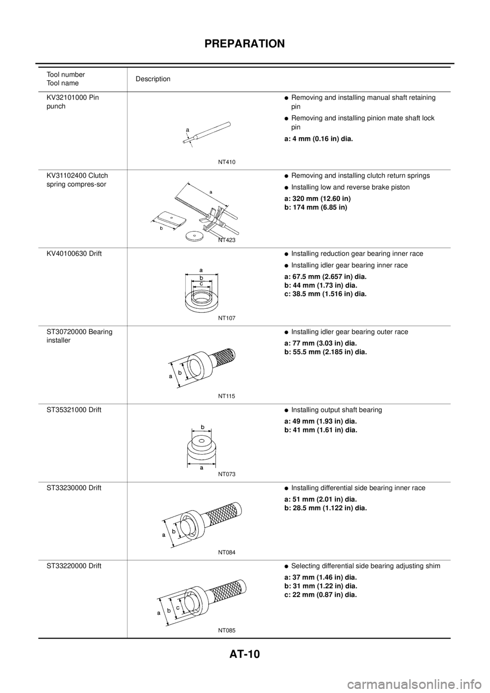
KV32101000 Pin
punchlRemoving and installing manual shaft retaining
pin
lRemoving and installing pinion mate shaft lock
pin
a: 4 mm (0.16 in) dia.
KV31102400 Clutch
spring compres-sor
lRemoving and installing clutch return springs
lInstalling low and reverse brake piston
a: 320 mm (12.60 in)
b: 174 mm (6.85 in)
KV40100630 Drift
lInstalling reduction gear bearing inner race
lInstalling idler gear bearing inner race
a: 67.5 mm (2.657 in) dia.
b: 44 mm (1.73 in) dia.
c: 38.5 mm (1.516 in) dia.
ST30720000 Bearing
installer
lInstalling idler gear bearing outer race
a: 77 mm (3.03 in) dia.
b: 55.5 mm (2.185 in) dia.
ST35321000 Drift
lInstalling output shaft bearing
a: 49 mm (1.93 in) dia.
b: 41 mm (1.61 in) dia.
ST33230000 Drift
lInstalling differential side bearing inner race
a: 51 mm (2.01 in) dia.
b: 28.5 mm (1.122 in) dia.
ST33220000 Drift
lSelecting differential side bearing adjusting shim
a: 37 mm (1.46 in) dia.
b: 31 mm (1.22 in) dia.
c: 22 mm (0.87 in) dia. Tool number
Tool nameDescription
NT410
NT423
NT107
NT115
NT073
NT084
NT085
Page 17 of 3066
PREPARATION
AT-11
D
E
F
G
H
I
J
K
L
MA
B
AT
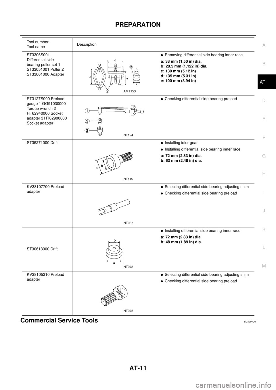
Commercial Service ToolsECS004Q6
ST3306S001
Differential side
bearing puller set 1
ST33051001 Puller 2
ST33061000 AdapterlRemoving differential side bearing inner race
a: 38 mm (1.50 in) dia.
b: 28.5 mm (1.122 in) dia.
c: 130 mm (5.12 in)
d: 135 mm (5.31 in)
e: 100 mm (3.94 in)
ST3127S000 Preload
gauge 1 GG91030000
To r q u e w r e n c h 2
HT62940000 Socket
adapter 3 HT62900000
Socket adapter
lChecking differential side bearing preload
ST35271000 Drift
lInstalling idler gear
lInstalling differential side bearing inner race
a: 72 mm (2.83 in) dia.
b: 63 mm (2.48 in) dia.
KV38107700 Preload
adapter
lSelecting differential side bearing adjusting shim
lChecking differential side bearing preload
ST30613000 Drift
lInstalling differential side bearing inner race
a: 72 mm (2.83 in) dia.
b: 48 mm (1.89 in) dia.
KV38105210 Preload
adapter
lSelecting differential side bearing adjusting shim
lChecking differential side bearing preload Tool number
To o l n a m eDescription
AMT153
NT124
NT115
NT087
NT073
NT075
Page 18 of 3066
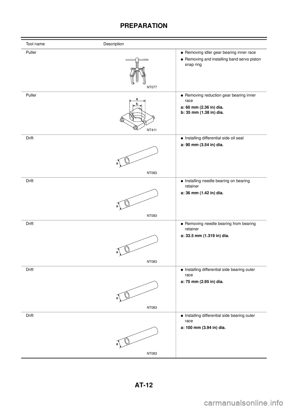
AT-12
PREPARATION
Tool name Description
Puller
lRemoving idler gear bearing inner race
lRemoving and installing band servo piston
snap ring
Puller
lRemoving reduction gear bearing inner
race
a: 60 mm (2.36 in) dia.
b: 35 mm (1.38 in) dia.
Drift
lInstalling differential side oil seal
a: 90 mm (3.54 in) dia.
Drift
lInstalling needle bearing on bearing
retainer
a: 36 mm (1.42 in) dia.
Drift
lRemoving needle bearing from bearing
retainer
a: 33.5 mm (1.319 in) dia.
Drift
lInstalling differential side bearing outer
race
a: 75 mm (2.95 in) dia.
Drift
lInstalling differential side bearing outer
race
a: 100 mm (3.94 in) dia.
NT077
NT411
NT083
NT083
NT083
NT083
NT083
Page 19 of 3066

A/T FLUID
AT-13
D
E
F
G
H
I
J
K
L
MA
B
AT
A/T FLUIDPFP:KLE40
Checking A/T FluidECS004Q7
1. Warm up engine.
2. Check for fluid leakage.
3. Before driving, fluid level can be checked at fluid temperatures
of 30 to 50°C (86 to 122°F) using “COLD” range on dipstick.
a. Park vehicle on level surface and set parking brake.
b. Start engine and move selector lever through each gear posi-
tion. Leave selector lever in “P” position.
c. Check fluid level with engine idling.
d. Remove dipstick and note reading. If level is at low side of either
range, and fluid to the charging pipe.
e. Re-insert dipstick into charging pipe as far as it will go.
f. Remove dipstick and note reading. If reading is at low side of range, add fluid to the charging pipe.
Do not overfill.
4. Drive vehicle for approximately 5 minutes in urban areas.
5. Re-check fluid level at fluid temperatures of 50 to 80°C (122 to 176°F) using “HOT” range on dipstick.
6. Check fluid condition.
lIf fluid is very dark or smells burned, refer to AT section for
checking operation of A/T. Flush cooling system after repair of
A/T.
lIf A/T fluid contains frictional material (clutches, bands, etc.),
replace radiator and flush cooler line using cleaning solvent
and compressed air after repair of A/T. Refer toCO-12,
"RADIATOR",CO-15, "RADIATOR (ALUMINUM TYPE)",,.
Changing A/T FluidECS004Q8
1. Warm up A/T fluid.
2. Stop engine.
3. Drain A/T fluid from drain plug and refill with new A/T fluid.
Always refill same volume with drained fluid.
4. Run engine at idle speed for five minutes.
5. Check fluid level and condition. Refer to “Checking A/T Fluid”. If fluid is still dirty, repeat steps 2 through 5.
SMA827CA
SMA853B
Fluid grade:
Genuine Nissan ATF or equivalent. Refer toMA-
17, "RECOMMENDED FLUIDS AND LUBRI-
CANTS".
Fluid capacity (With torque converter):
Approx. 8.0 (7.01 lmp qt)
Drain plug:
:29-39N·m(3.0-4.0kg-m,22-29ft-lb)
SMA027D
Page 20 of 3066

AT-14
OVERALL SYSTEM
OVERALL SYSTEM
PFP:00000
A/T Electrical Parts LocationECS004Q9