jump start NISSAN X-TRAIL 2003 Electronic Repair Manual
[x] Cancel search | Manufacturer: NISSAN, Model Year: 2003, Model line: X-TRAIL, Model: NISSAN X-TRAIL 2003Pages: 3066, PDF Size: 51.47 MB
Page 427 of 3066
![NISSAN X-TRAIL 2003 Electronic Repair Manual TORQUE CONVERTER CLUTCH SOLENOID VALVE
AT-421
[ALL]
D
E
F
G
H
I
J
K
L
MA
B
AT
TORQUE CONVERTER CLUTCH SOLENOID VALVEPFP:31940
DescriptionECS0 04 U4
The torque converter clutch solenoid valve is activa NISSAN X-TRAIL 2003 Electronic Repair Manual TORQUE CONVERTER CLUTCH SOLENOID VALVE
AT-421
[ALL]
D
E
F
G
H
I
J
K
L
MA
B
AT
TORQUE CONVERTER CLUTCH SOLENOID VALVEPFP:31940
DescriptionECS0 04 U4
The torque converter clutch solenoid valve is activa](/img/5/57402/w960_57402-426.png)
TORQUE CONVERTER CLUTCH SOLENOID VALVE
AT-421
[ALL]
D
E
F
G
H
I
J
K
L
MA
B
AT
TORQUE CONVERTER CLUTCH SOLENOID VALVEPFP:31940
DescriptionECS0 04 U4
The torque converter clutch solenoid valve is activated, with the gear
in “D
4”, by the TCM in response to signals sent from the vehicle
speed and throttle position sensors. Lock-up piston operation will
then be controlled.
Lock-up operation, however, is prohibited when A/T fluid tempera-
ture is too low.
When the accelerator pedal is depressed (less than 2/8) in lock-up
condition, the engine speed should not change abruptly. If there is a
big jump in engine speed, there is no lock-up.
CONSULT-II REFERENCE VALUE IN DATA MONITOR MODE
Remarks: Specification data are reference values.
TCM TERMINALS AND REFERENCE VALUE
Remarks: Specification data are reference values.
ON BOARD DIAGNOSIS LOGIC
SELF-DIAGNOSIS CODE CONFIRMATION PROCEDURE
After the repair, perform the following procedure to confirm the malfunction is eliminated.
With CONSULT-II
1. Start engine.
2. Select “SELF-DIAG RESULTS” mode for A/T with CONSULT-II.
3. DrivevehicleinD
1®D2®D3®D4®D4lock-up position.
SCIA0718E
Monitor item Condition Specification
Torque converter clutch solenoid valve
dutyLock-up “OFF”
¯
Lock-up “ON”Approximately 4%
¯
Approximately 94%
Te r m i -
nal No.Wire color Item ConditionJudgement stan-
dard
(Approx.)
3GY/RTorque converter
clutch solenoid
valveWhen A/T performs lock-up. 8 - 15V
When A/T does not perform lock-up. 0V
Diagnostic trouble code Malfunction is detected when... Check items (Possible cause)
: T/C CLUTCH SOL/V
TCM detects an improper voltage drop
when it tries to operate the solenoid valve.
lHarness or connectors
(The solenoid circuit is open or shorted.)
lT/C clutch solenoid valve
: 7th judgement flicker
SAT014K
Page 1908 of 3066
![NISSAN X-TRAIL 2003 Electronic Repair Manual EC-794
[YD]
DTC P1660 BATTERY VOLTAGE
DTC P1660 BATTERY VOLTAGE
PFP:AYBGL
On Board Diagnosis LogicEBS0035A
The ECM checks if battery voltage is within the tolerance range for the engine control system NISSAN X-TRAIL 2003 Electronic Repair Manual EC-794
[YD]
DTC P1660 BATTERY VOLTAGE
DTC P1660 BATTERY VOLTAGE
PFP:AYBGL
On Board Diagnosis LogicEBS0035A
The ECM checks if battery voltage is within the tolerance range for the engine control system](/img/5/57402/w960_57402-1907.png)
EC-794
[YD]
DTC P1660 BATTERY VOLTAGE
DTC P1660 BATTERY VOLTAGE
PFP:AYBGL
On Board Diagnosis LogicEBS0035A
The ECM checks if battery voltage is within the tolerance range for the engine control system.
DTC Confirmation ProcedureEBS0035B
With CONSULT-II
1. Check the following.
–Jumper cables are connected for jump starting.
–Battery or alternator has been replaced.
If the result is “Yes” for one item or more, skip the following steps and go toEC-794, "
Diagnostic Proce-
dure".
2. Check that the positive battery terminal is connected to battery properly. If NG, reconnect it properly.
3. Check that the alternator functions properly. Refer toSC-12, "
CHARGING SYSTEM".
4. Turn ignition switch “ON” and select “DATA MONITOR” mode with CONSULT-II.
5. Wait one minute.
6. If DTC is detected, go toEC-794, "
Diagnostic Procedure".
If DTC is not detected, go to next step.
7. Start engine and wait one minute at idle.
8. If DTC is detected, go toEC-794, "
Diagnostic Procedure".
Diagnostic ProcedureEBS0035C
1.INSPECTION START
Are jumper cables connected for the jump starting?
Ye s o r N o
Yes >>GOTO3.
No >> GO TO 2.
2.CHECK BATTERY AND ALTERNATOR
Check that the proper type of battery and alternator is installed.
Refer toSC-3, "
BATTERY",SC-12, "CHARGING SYSTEM".
OK or NG
OK >> GO TO 5.
NG >> Replace with a proper one.
DTC Malfunction is detected when ... Check Items (Possible Cause)
P1660
lAn abnormally high or low voltage from the battery
is sent to ECM.lIncorrect jump starting
lBattery
lAlternator
lECM
Page 2281 of 3066

GI-28
SERVICE INFORMATION FOR ELECTRICAL INCIDENT
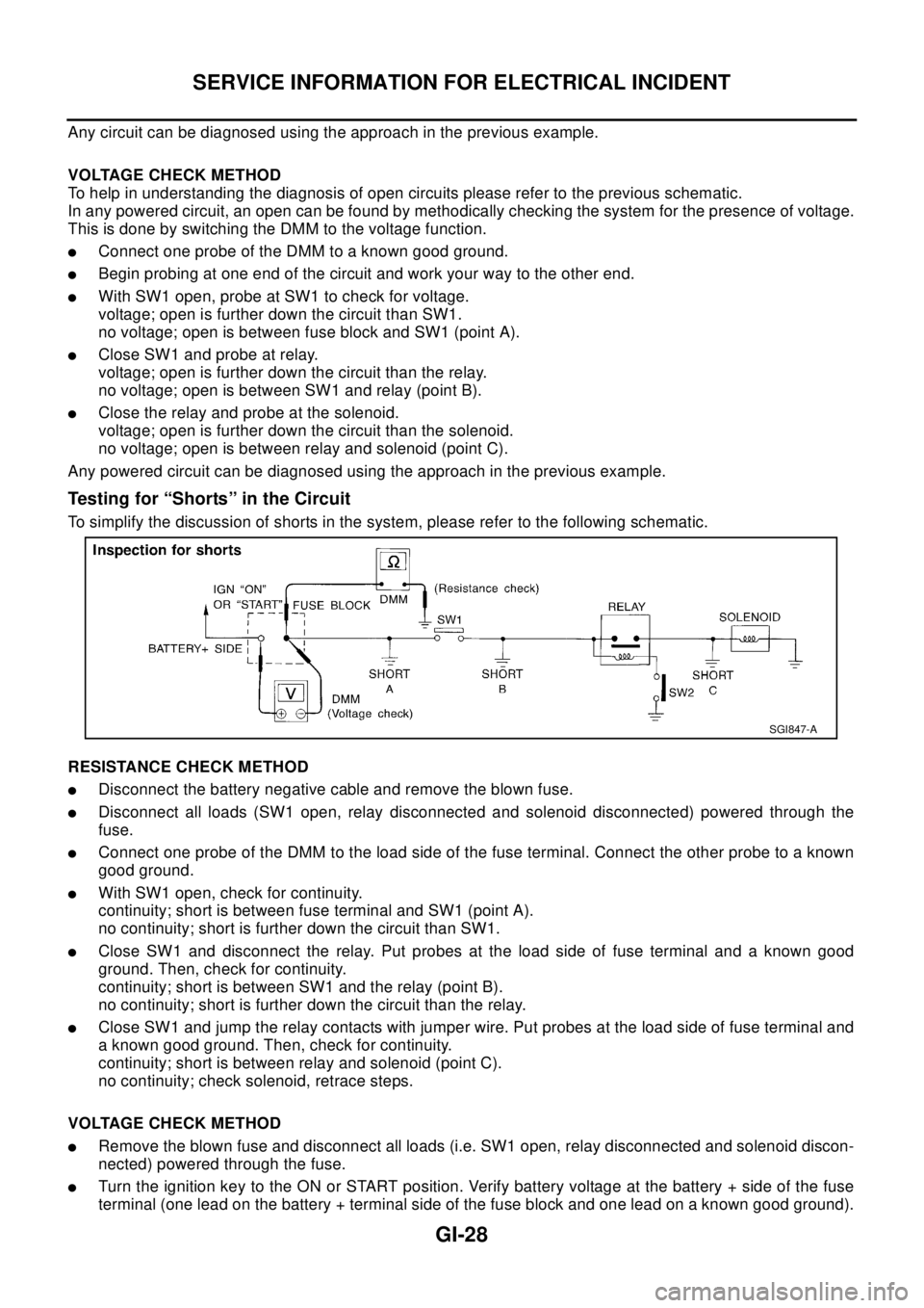
Any circuit can be diagnosed using the approach in the previous example.
VOLTAGE CHECK METHOD
To help in understanding the diagnosis of open circuits please refer to the previous schematic.
In any powered circuit, an open can be found by methodically checking the system for the presence of voltage.
This is done by switching the DMM to the voltage function.
lConnect one probe of the DMM to a known good ground.
lBegin probing at one end of the circuit and work your way to the other end.
lWith SW1 open, probe at SW1 to check for voltage.
voltage; open is further down the circuit than SW1.
no voltage; open is between fuse block and SW1 (point A).
lClose SW1 and probe at relay.
voltage; open is further down the circuit than the relay.
no voltage; open is between SW1 and relay (point B).
lClose the relay and probe at the solenoid.
voltage; open is further down the circuit than the solenoid.
no voltage; open is between relay and solenoid (point C).
Any powered circuit can be diagnosed using the approach in the previous example.
Testing for “Shorts” in the Circuit
To simplify the discussion of shorts in the system, please refer to the following schematic.
RESISTANCE CHECK METHOD
lDisconnect the battery negative cable and remove the blown fuse.
lDisconnect all loads (SW1 open, relay disconnected and solenoid disconnected) powered through the
fuse.
lConnect one probe of the DMM to the load side of the fuse terminal. Connect the other probe to a known
good ground.
lWith SW1 open, check for continuity.
continuity; short is between fuse terminal and SW1 (point A).
no continuity; short is further down the circuit than SW1.
lClose SW1 and disconnect the relay. Put probes at the load side of fuse terminal and a known good
ground. Then, check for continuity.
continuity; short is between SW1 and the relay (point B).
no continuity; short is further down the circuit than the relay.
lClose SW1 and jump the relay contacts with jumper wire. Put probes at the load side of fuse terminal and
a known good ground. Then, check for continuity.
continuity; short is between relay and solenoid (point C).
no continuity; check solenoid, retrace steps.
VOLTAGE CHECK METHOD
lRemove the blown fuse and disconnect all loads (i.e. SW1 open, relay disconnected and solenoid discon-
nected) powered through the fuse.
lTurn the ignition key to the ON or START position. Verify battery voltage at the battery + side of the fuse
terminal (one lead on the battery + terminal side of the fuse block and one lead on a known good ground).
SGI847-A
Page 2875 of 3066

BATTERY
SC-3
C
D
E
F
G
H
I
J
L
MA
B
SC
BATTERYPFP:00011
How to Handle BatteryEKS00313
CAUTION:
lIf it becomes necessary to start the engine with a booster battery and jumper cables, use a 12-volt
booster battery.
lAfter connecting battery cables, ensure that they are tightly clamped to battery terminals for good
contact.
lNever add distilled water through the hole used to check specific gravity.
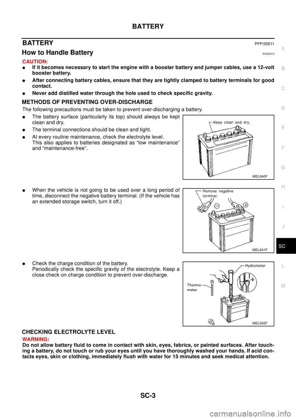
METHODS OF PREVENTING OVER-DISCHARGE
The following precautions must be taken to prevent over-discharging a battery.
lThe battery surface (particularly its top) should always be kept
clean and dry.
lThe terminal connections should be clean and tight.
lAt every routine maintenance, check the electrolyte level.
This also applies to batteries designated as “low maintenance”
and “maintenance-free”.
lWhen the vehicle is not going to be used over a long period of
time, disconnect the negative battery terminal. (If the vehicle has
an extended storage switch, turn it off.)
lCheck the charge condition of the battery.
Periodically check the specific gravity of the electrolyte. Keep a
close check on charge condition to prevent over-discharge.
CHECKING ELECTROLYTE LEVEL
WA RN ING:
Do not allow battery fluid to come in contact with skin, eyes, fabrics, or painted surfaces. After touch-
ing a battery, do not touch or rub your eyes until you have thoroughly washed your hands. If acid con-
tacts eyes, skin or clothing, immediately flush with water for 15 minutes and seek medical attention.
MEL040F
MEL041F
MEL042F