Front ach OPEL FRONTERA 1998 User Guide
[x] Cancel search | Manufacturer: OPEL, Model Year: 1998, Model line: FRONTERA, Model: OPEL FRONTERA 1998Pages: 6000, PDF Size: 97 MB
Page 705 of 6000

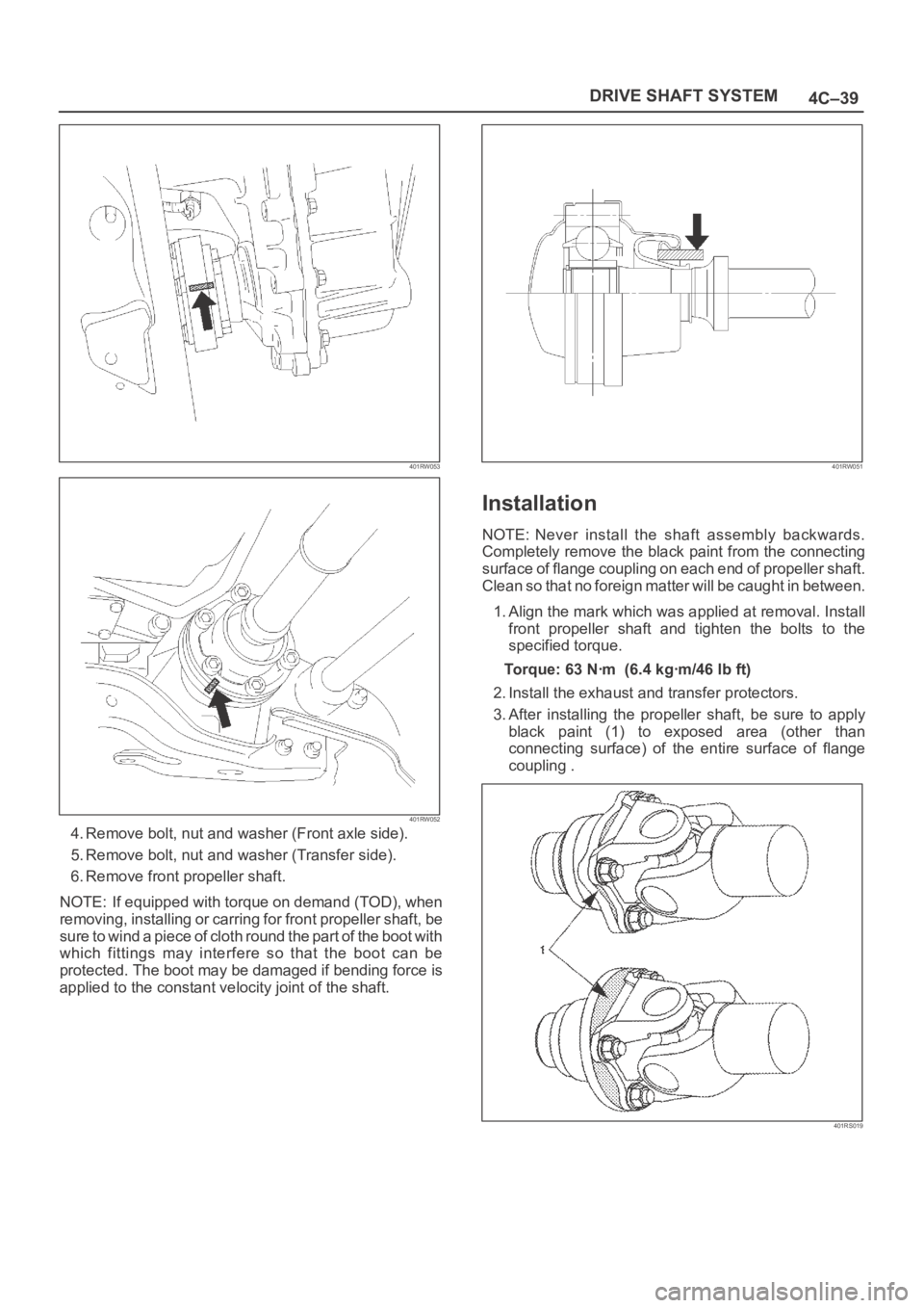
4C–39 DRIVE SHAFT SYSTEM
401RW053
401RW052
4. Remove bolt, nut and washer (Front axle side).
5. Remove bolt, nut and washer (Transfer side).
6. Remove front propeller shaft.
NOTE: If equipped with torque on demand (TOD), when
removing, installing or carring for front propeller shaft, be
sure to wind a piece of cloth round the part of the boot with
which fittings may interfere so that the boot can be
protected. The boot may be damaged if bending force is
applied to the constant velocity joint of the shaft.
401RW051
Installation
NOTE: Never install the shaft assembly backwards.
Completely remove the black paint from the connecting
surface of flange coupling on each end of propeller shaft.
Clean so that no foreign matter will be caught in between.
1. Align the mark which was applied at removal. Install
front propeller shaft and tighten the bolts to the
specified torque.
Torque:63Nꞏm (6.4kgꞏm/46lbft)
2. Install the exhaust and transfer protectors.
3. After installing the propeller shaft, be sure to apply
black paint (1) to exposed area (other than
connecting surface) of the entire surface of flange
coupling .
401RS019
Page 710 of 6000

4C–44
DRIVE SHAFT SYSTEM
401RW047
Front Axle Flange Run-out
1. Set a dial gage at right angle near the outer
circumference of the flange face and check the
run-out of the flange face.
Limit: 0.15 mm (0.006 in)
401RW046
2. Set a dial gage at right angle near the inner
circumference and check the run-out of the flange.
Limit: 0.15 mm (0.006 in)
401RW045
3. If vibration is felt during the 4H AUTO drive, disconnct
the propeller shaft at the front axle. Reinstall the
propeller shaft at 60
, 120, 180, 240, and 300
and conduct test drive in each position and check if
there is vibration.
401RW044
Page 715 of 6000

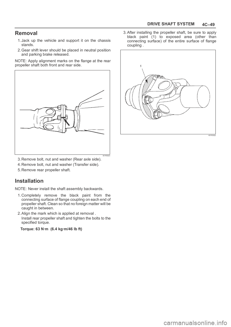
4C–49 DRIVE SHAFT SYSTEM
Removal
1. Jack up the vehicle and support it on the chassis
stands.
2. Gear shift lever should be placed in neutral position
and parking brake released.
NOTE: Apply alignment marks on the flange at the rear
propeller shaft both front and rear side.
401RS023
3. Remove bolt, nut and washer (Rear axle side).
4. Remove bolt, nut and washer (Transfer side).
5. Remove rear propeller shaft.
Installation
NOTE: Never install the shaft assembly backwards.
1. Completely remove the black paint from the
connecting surface of flange coupling on each end of
propeller shaft. Clean so that no foreign matter will be
caught in between.
2. Align the mark which is applied at removal .
Install rear propeller shaft and tighten the bolts to the
specified torque.
Torque: 63 Nꞏm (6.4 kgꞏm/46 lb ft)3. After installing the propeller shaft, be sure to apply
black paint (1) to exposed area (other than
connecting surface) of the entire surface of flange
coupling .
401RS022
Page 735 of 6000

4D1–14
TRANSFER CASE (STANDARD TYPE)
6. Join the rod grooves of 2WD–4WD actuator
assembly (12) and shift rod (11).
220RW030
Legend
(11) Shift Rod: 2WD–4WD (Position: 4WD)
(12) 2WD–4WD Actuator Assembly (Mode: 2WD)
(13) Rear Cover Assembly
7. Push the 2WD–4WD actuator assembly (12) with
2WD–4WD shift rod (11) till the shift rod (11) reaches
the 2WD position.
220RW031
Legend
(14) Position: 2WD
(15) Mode: 2WD
8. Tighten the 2WD–4WD actuator bolts to the specified
torque.
Torque: 19 Nꞏm (1.9kgꞏm/14 lb ft)
9. Install the actuator heat protector.
10. Connect the actuator breather hose to the actuator.11. Install the control box assembly.
Torque: 19 Nꞏm (1.9kgꞏm/14 lb ft)
12. Connect the breather hoses to the control box.
13. Install the rear companion flange and front
companion flange, using the companion flange holder
5–8840–0133–0 (J–8614–11) to tighten the flange
nuts to the transfer case.
262RW067
14. Tighten the new transfer flange nuts to the specified
torque.
To r q u e
Rear companion flange: 167 Nꞏm (17.0kgꞏm/123
lb ft)
Front companion flange: 137 Nꞏm (14.0kgꞏm/101
lb ft)
15. Use the punch 5–8840–2293–0 (J–39209) to stake
the rear companion flange nut at two spots.
266RW027
Page 754 of 6000

TRANSFER CASE (STANDARD TYPE)
4D1–33
NOTE: Do not reuse the stopper plate. (Shift On The Fly
model)
24. Disassemble the 2WD–4WD clutch hub and sleeve
assembly.
Springs (1) (Shift On The Fly model)
Inserts (2) (Shift On The Fly model)
Clutch Hub (3)
Sleeve (4)
226RW133
25. Use a bench press and the ball bearing remover
5–8840–0015–0 (J–22912–01) to remove the ball
bearing (4) from front output shaft (5).
262RW071
26. Remove bearing snap ring (29) from transfer case.
27. Remove the counter gear assembly (28) from the
transfer case (1).
28. Use a pair of snap ring pliers to remove the snap ring
(20).29. Use a bench press and the bearing remover
5–8840–0015–0 (J–22912–01) to remove the ball
bearing (21).
30. Use a pair of snap ring pliers to remove the snap ring
(27).
31. Use a bench press and the bearing remover
5–8840–0015–0 (J–22912–01) to remove the ball
bearing (26).
226RW191
32. Remove the spacer (25).
33. Remove the belleville spring (24).
34. Remove the sub–gear (anti–lash plate) (23) from the
counter gear (22).
Inspection and Repair
1. Make the necessary repair or parts replacement if
wear, damage or any other abnormal conditions are
found during inspection.
2. Wash all parts thoroughly in clean solvent. Be sure all
old lubricant, metallic particles, dirt, or foreign
material are removed from the surfaces of every part.
Apply compressed air to each oil feed port and
channel in each case half to remove any obstructions
or cleaning solvent residue.
Gears
1. Inspect all the gear teeth for signs of excessive wear
or damage and check all the gear splines for burrs,
nicks, wear or damage. Remove the minor nicks or
scratches on an oil stone. Replace any part exhibiting
excessive wear or damage.
Front Output Gear Inside Diameter
1. Use an inside dial indicator to measure the gear inside
diameter.
Page 759 of 6000

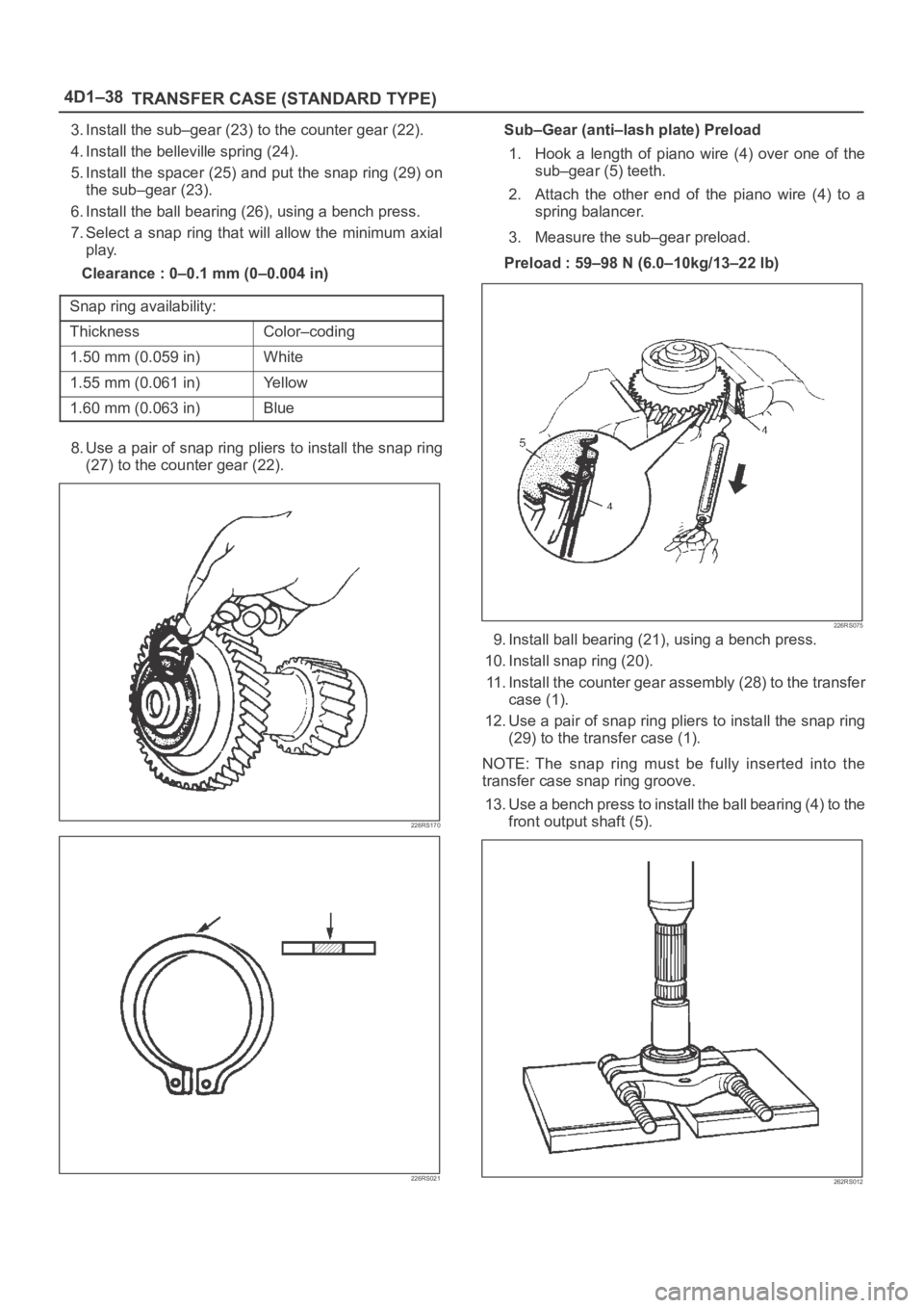
4D1–38
TRANSFER CASE (STANDARD TYPE)
3. Install the sub–gear (23) to the counter gear (22).
4. Install the belleville spring (24).
5. Install the spacer (25) and put the snap ring (29) on
the sub–gear (23).
6. Install the ball bearing (26), using a bench press.
7. Select a snap ring that will allow the minimum axial
play.
Clearance : 0–0.1 mm (0–0.004 in)
Snap ring availability:
ThicknessColor–coding
1.50 mm (0.059 in)White
1.55 mm (0.061 in)Yellow
1.60 mm (0.063 in)Blue
8. Use a pair of snap ring pliers to install the snap ring
(27) to the counter gear (22).
226RS170
226RS021
Sub–Gear (anti–lash plate) Preload
1. Hook a length of piano wire (4) over one of the
sub–gear (5) teeth.
2. Attach the other end of the piano wire (4) to a
spring balancer.
3. Measure the sub–gear preload.
Preload : 59–98 N (6.0–10kg/13–22 lb)
226RS075
9. Install ball bearing (21), using a bench press.
10. Install snap ring (20).
11. Install the counter gear assembly (28) to the transfer
case (1).
12. Use a pair of snap ring pliers to install the snap ring
(29) to the transfer case (1).
NOTE: The snap ring must be fully inserted into the
transfer case snap ring groove.
13. Use a bench press to install the ball bearing (4) to the
front output shaft (5).
262RS012
Page 760 of 6000

TRANSFER CASE (STANDARD TYPE)
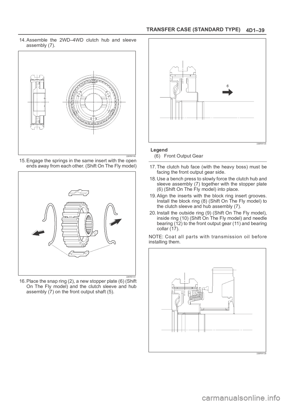
4D1–39
14. Assemble the 2WD–4WD clutch hub and sleeve
assembly (7).
226RW140
15. Engage the springs in the same insert with the open
ends away from each other. (Shift On The Fly model)
226RW141
16. Place the snap ring (2), a new stopper plate (6) (Shift
On The Fly model) and the clutch sleeve and hub
assembly (7) on the front output shaft (5).
226RW135
Legend
(6) Front Output Gear
17. The clutch hub face (with the heavy boss) must be
facing the front output gear side.
18. Use a bench press to slowly force the clutch hub and
sleeve assembly (7) together with the stopper plate
(6) (Shift On The Fly model) into place.
19. Align the inserts with the block ring insert grooves.
Install the block ring (8) (Shift On The Fly model) to
the clutch sleeve and hub assembly (7).
20. Install the outside ring (9) (Shift On The Fly model),
inside ring (10) (Shift On The Fly model) and needle
bearing (12) to the front output gear (11) and bearing
collar (17).
NOTE: Coat all parts with transmission oil before
installing them.
226RW139
Page 762 of 6000

TRANSFER CASE (STANDARD TYPE)
4D1–41
27. Use a pair of snap ring pliers to install the snap ring
(19) to the output shaft (5).
Sub gear (anti lash plate) preload (M/T)
1. Hook a length of piano wire (4) over one of the
sub–gear (5) teeth.
2. Attach the other end of the piano wire to (4) a
spring balancer.
3. Measure the sub–gear preload.
Preload: 59–98 N (6.0–10.0kg/13–22 lb)
(M/T)
226RS075
28. Install front output gear assembly (3) to the transfer
case (1).
29. Use a pair of snap ring pliers to install the snap ring (2)
to the transfer case (1).
NOTE: The snap ring must be fully inserted into the
transfer case snap ring groove.
30. Use a bench press to install the ball bearing (32) to the
input shaft (31).
265RS003
31. Install the plate (34), ball (35), and bearing collar (36)
and place the snap ring (33).
32. Install the needle bearing (37) and input gear (38).
33. The clutch hub face (with the heavy boss) must be
facing the transfer input gear side (7).
226RW136
34. Install the high–low clutch hub and sleeve (39), using
a bench press.
35. Install the input shaft assembly (30) to the transfer
case (1).
36. Install the snap ring (33) to the transfer case (1).
NOTE: The snap ring must be fully inserted into the
transfer case snap ring groove.
37. Install the front companion flange temporarily and use
the flange holder 5–8840–0133–0 (J–8614–11) and
lock nut wrench 5–8840–2156–0 (J–37219) to install
the lock nut (40).
Torque: 137 Nꞏm (14.0kgꞏm/101 lb ft)
226RW190
38. Use the punch to stake the lock nut (40) at one spot.
Page 782 of 6000

4D2–15 TRANSFER CASE (TOD)
4. Apply a thin coat of grease to the seal ring of each
front and rear speed sensor, and mount the sensors
carefully.
5. Tighten the bolts to the specified torque.
Torque : 5 Nꞏm (0.5 kgꞏm/43 lb in)
NOTE: Pay attention not to mount the front (or rear)
sensor to the rear (or front) sensor position.
6. Install the ball bearing (1) for the front output shaft as
flat as shown in the figure.
261RW008
7. Mount the coil assembly and tighten the nuts to the
specified torque.
Torque : 10 Nꞏm (1.0 kgꞏm/87 lb in)
8. Connect the terminal in the central connector.
NOTE: Be careful not to damage other terminals.
9. Install speed gear and tone wheel.
10. Mount the ball bearing (2) as flat as shown in the
figure.
261RW009–1
11. Using snap ring pliers, install the snap ring to the
transfer cover assembly.NOTE: Securely install the snap ring to the groove of the
transfer cover assembly.
Page 802 of 6000

4D2–35 TRANSFER CASE (TOD)
2. Mount the front output shaft to the transfer case.
266RW012
3. Install the shifter lever shaft.
4. Install the snap ring.
5. Install the reduction lever assembly to the shifter lever
shaft and fix the assembly with the snap ring.
261RW021
6. Install the cam to the cam pilot block.
7. Attach the washer to the cam pilot block and fix the
washer with the snap ring.
261RW029
8. Mount the reduction fork to the lock-up shaft.
9. Install the spring pin to the reduction fork and lock-up
roll.
261RW020