Front ach OPEL FRONTERA 1998 Owner's Manual
[x] Cancel search | Manufacturer: OPEL, Model Year: 1998, Model line: FRONTERA, Model: OPEL FRONTERA 1998Pages: 6000, PDF Size: 97 MB
Page 813 of 6000
5A–3 BRAKE CONTROL SYSTEM
General Description
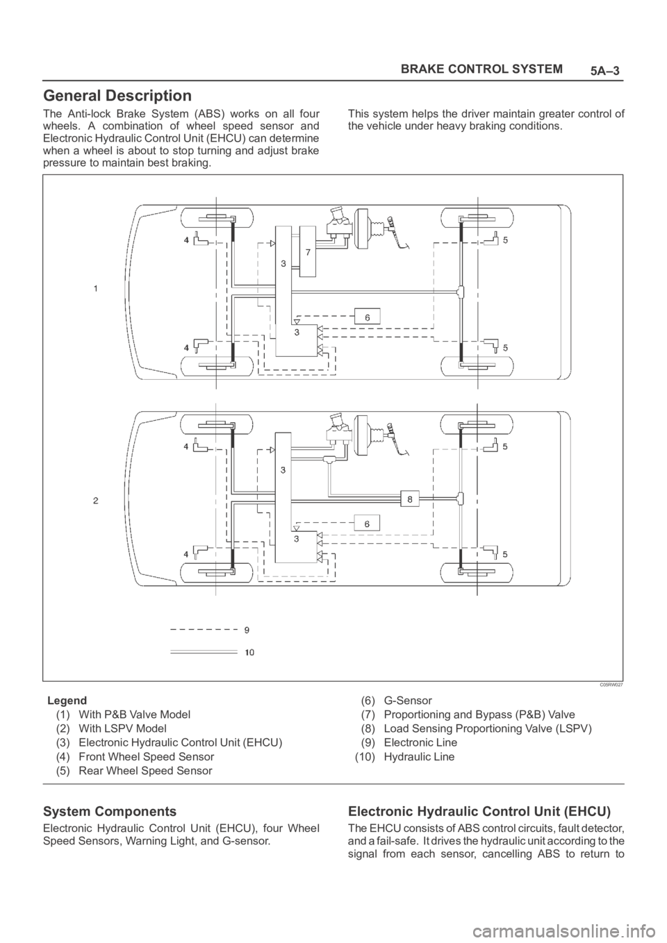
The Anti-lock Brake System (ABS) works on all four
wheels. A combination of wheel speed sensor and
Electronic Hydraulic Control Unit (EHCU) can determine
when a wheel is about to stop turning and adjust brake
pressure to maintain best braking.This system helps the driver maintain greater control of
the vehicle under heavy braking conditions.
C05RW027
Legend
(1) With P&B Valve Model
(2) With LSPV Model
(3) Electronic Hydraulic Control Unit (EHCU)
(4) Front Wheel Speed Sensor
(5) Rear Wheel Speed Sensor(6) G-Sensor
(7) Proportioning and Bypass (P&B) Valve
(8) Load Sensing Proportioning Valve (LSPV)
(9) Electronic Line
(10) Hydraulic Line
System Components
Electronic Hydraulic Control Unit (EHCU), four Wheel
Speed Sensors, Warning Light, and G-sensor.
Electronic Hydraulic Control Unit (EHCU)
T h e E H C U c o n s i s t s o f A B S c o n t r o l c i r c u i t s , f a u l t d e t e c t o r,
and a fail-safe. It drives the hydraulic unit according to the
signal from each sensor, cancelling ABS to return to
Page 814 of 6000
5A–4
BRAKE CONTROL SYSTEM
normal braking when a malfunction has occurred in the
ABS.
The EHCU has a self-diagnosing function which can
indicate faulty circuits during diagnosis.
The EHCU is mounted on the engine compartment front
right side. It consists of a Motor, Plunger Pump, Solenoid
Valves and Check Valve.
On the outside, the relay box containing a motor relay and
a valve relay is installed.
Solenoid Valves: Reduces or holds the caliper fluid
pressure for each front disc brake or both rear disc brakes
according to the signal sent from the EHCU.
Reservoir: Temporarily holds the brake fluid that returns
from the front and rear disc brake caliper so that pressure
of front disc brake caliper can be reduced smoothly.
Plunger Pump: Feeds the brake fluid held in the reservoir
to the master cylinder.
Motor: Drives the pump according to the signal from
EHCU.
Check Valve: Controls the brake fluid flow.
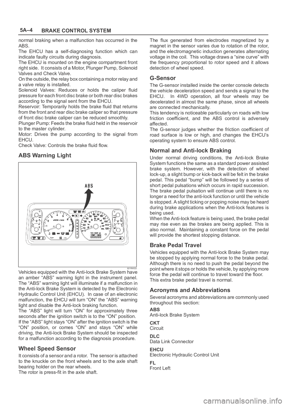
ABS Warning Light
821RW033Vehicles equipped with the Anti-lock Brake System have
an amber “ABS” warning light in the instrument panel.
The “ABS” warning light will illuminate if a malfunction in
the Anti-lock Brake System is detected by the Electronic
Hydraulic Control Unit (EHCU). In case of an electronic
malfunction, the EHCU will turn “ON” the “ABS” warning
light and disable the Anti-lock braking function.
The “ABS” light will turn “ON” for approximately three
seconds after the ignition switch is to the “ON” position.
If the “ABS” light stays “ON” after the ignition switch is the
“ON” position, or comes “ON” and stays “ON” while
driving, the Anti-lock Brake System should be inspected
for a malfunction according to the diagnosis procedure.
Wheel Speed Sensor
It consists of a sensor and a rotor. The sensor is attached
to the knuckle on the front wheels and to the axle shaft
bearing holder on the rear wheels.
The rotor is press-fit in the axle shaft.The flux generated from electrodes magnetized by a
magnet in the sensor varies due to rotation of the rotor,
and the electromagnetic induction generates alternating
voltage in the coil. This voltage draws a “sine curve” with
the frequency proportional to rotor speed and it allows
detection of wheel speed.
G-Sensor
The G-sensor installed inside the center console detects
the vehicle deceleration speed and sends a signal to the
EHCU. In 4WD operation, all four wheels may be
decelerated in almost the same phase, since all wheels
are connected mechanically.
This tendency is noticeable particularly on roads with low
friction coefficient, and the ABS control is adversely
affected.
The G-sensor judges whether the friction coefficient of
road surface is low or high, and changes the EHCU’s
operating system to ensure ABS control.
Normal and Anti-lock Braking
Under normal driving conditions, the Anti-lock Brake
System functions the same as a standard power assisted
brake system. However, with the detection of wheel
lock-up, a slight bump or kick-back will be felt in the brake
pedal. This pedal “bump” will be followed by a series of
short pedal pulsations which occurs in rapid succession.
The brake pedal pulsation will continue until there is no
longer a need for the anti-lock function or until the vehicle
is stopped. A slight ticking or popping noise may be heard
during brake applications when the Anti-lock features is
being used.
When the Anti-lock feature is being used, the brake pedal
may rise even as the brakes are being applied. This is
also normal. Maintaining a constant force on the pedal
will provide the shortest stopping distance.
Brake Pedal Travel
Vehicles equipped with the Anti-lock Brake System may
be stopped by applying normal force to the brake pedal.
Although there is no need to push the pedal beyond the
point where it stops or holds the vehicle, by applying more
force the pedal will continue to travel toward the floor.
This extra brake pedal travel is normal.
Acronyms and Abbreviations
Several acronyms and abbreviations are commonly used
throughout this section:
ABS
Anti-lock Brake System
CKT
Circuit
DLC
Data Link Connector
EHCU
Electronic Hydraulic Control Unit
FL
Front Left
Page 821 of 6000
5A–11 BRAKE CONTROL SYSTEM
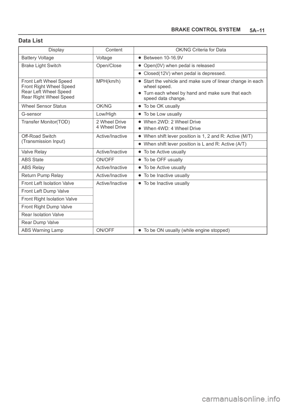
Data List
DisplayContentOK/NG Criteria for Data
Battery VoltageVo l t a g eBetween 10-16.9V
Brake Light SwitchOpen/CloseOpen(0V) when pedal is released
Closed(12V) when pedal is depressed.
Front Left Wheel Speed
Front Right Wheel Speed
Rear Left Wheel Speed
Rear Right Wheel SpeedMPH(km/h)Start the vehicle and make sure of linear change in each
wheel speed.
Turn each wheel by hand and make sure that each
speed data change.
Wheel Sensor StatusOK/NGTo be OK usually
G-sensorLow/HighTo be Low usually
Transfer Monitor(TOD)2 Wheel Drive
4 Wheel DriveWhen 2WD: 2 Wheel Drive
When 4WD: 4 Wheel Drive
Off-Road Switch
(Transmission Input)
Active/InactiveWhen shift lever position is 1, 2 and R: Active (M/T)
(Transmission Input)When shift lever position is L and R: Active (A/T)
Valve RelayActive/InactiveTo be Active usually
ABS StateON/OFFTo be OFF usually
ABS RelayActive/InactiveTo be Active usually
Return Pump RelayActive/InactiveTo be Inactive usually
Front Left Isolation ValveActive/InactiveTo be Inactive usually
Front Left Dump Valve
Front Right Isolation Valve
Front Right Dump Valve
Rear Isolation Valve
Rear Dump Valve
ABS Warning LampON/OFFTo be ON usually (while engine stopped)
Page 845 of 6000
5A–35 BRAKE CONTROL SYSTEM
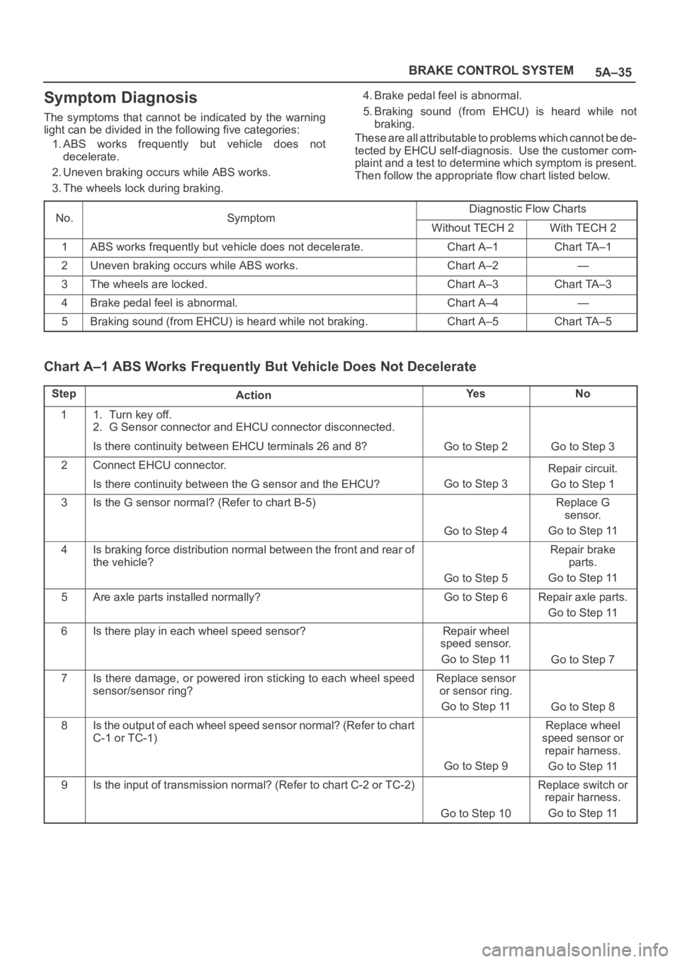
Symptom Diagnosis
The symptoms that cannot be indicated by the warning
light can be divided in the following five categories:
1. ABS works frequently but vehicle does not
decelerate.
2. Uneven braking occurs while ABS works.
3. The wheels lock during braking.4. Brake pedal feel is abnormal.
5. Braking sound (from EHCU) is heard while not
braking.
These are all attributable to problems which cannot be de-
tected by EHCU self-diagnosis. Use the customer com-
plaint and a test to determine which symptom is present.
Then follow the appropriate flow chart listed below.
NoSymptomDiagnostic Flow ChartsNo.Sym tomWithout TECH 2With TECH 2
1ABS works frequently but vehicle does not decelerate.Chart A–1Chart TA–1
2Uneven braking occurs while ABS works.Chart A–2—
3The wheels are locked.Chart A–3Chart TA–3
4Brake pedal feel is abnormal.Chart A–4—
5Braking sound (from EHCU) is heard while not braking. Chart A–5Chart TA–5
Chart A–1 ABS Works Frequently But Vehicle Does Not Decelerate
StepActionYe sNo
11. Turn key off.
2. G Sensor connector and EHCU connector disconnected.
Is there continuity between EHCU terminals 26 and 8?
Go to Step 2Go to Step 3
2Connect EHCU connector.
Is there continuity between the G sensor and the EHCU?
Go to Step 3
Repair circuit.
Go to Step 1
3Is the G sensor normal? (Refer to chart B-5)
Go to Step 4
Replace G
sensor.
Go to Step 11
4Is braking force distribution normal between the front and rear of
the vehicle?
Go to Step 5
Repair brake
parts.
Go to Step 11
5Are axle parts installed normally?Go to Step 6Repair axle parts.
Go to Step 11
6Is there play in each wheel speed sensor?Repair wheel
speed sensor.
Go to Step 11
Go to Step 7
7Is there damage, or powered iron sticking to each wheel speed
sensor/sensor ring?Replace sensor
or sensor ring.
Go to Step 11
Go to Step 8
8Is the output of each wheel speed sensor normal? (Refer to chart
C-1 or TC-1)
Go to Step 9
Replace wheel
speed sensor or
repair harness.
Go to Step 11
9Is the input of transmission normal? (Refer to chart C-2 or TC-2)
Go to Step 10
Replace switch or
repair harness.
Go to Step 11
Page 970 of 6000
6A–14
ENGINE MECHANICAL
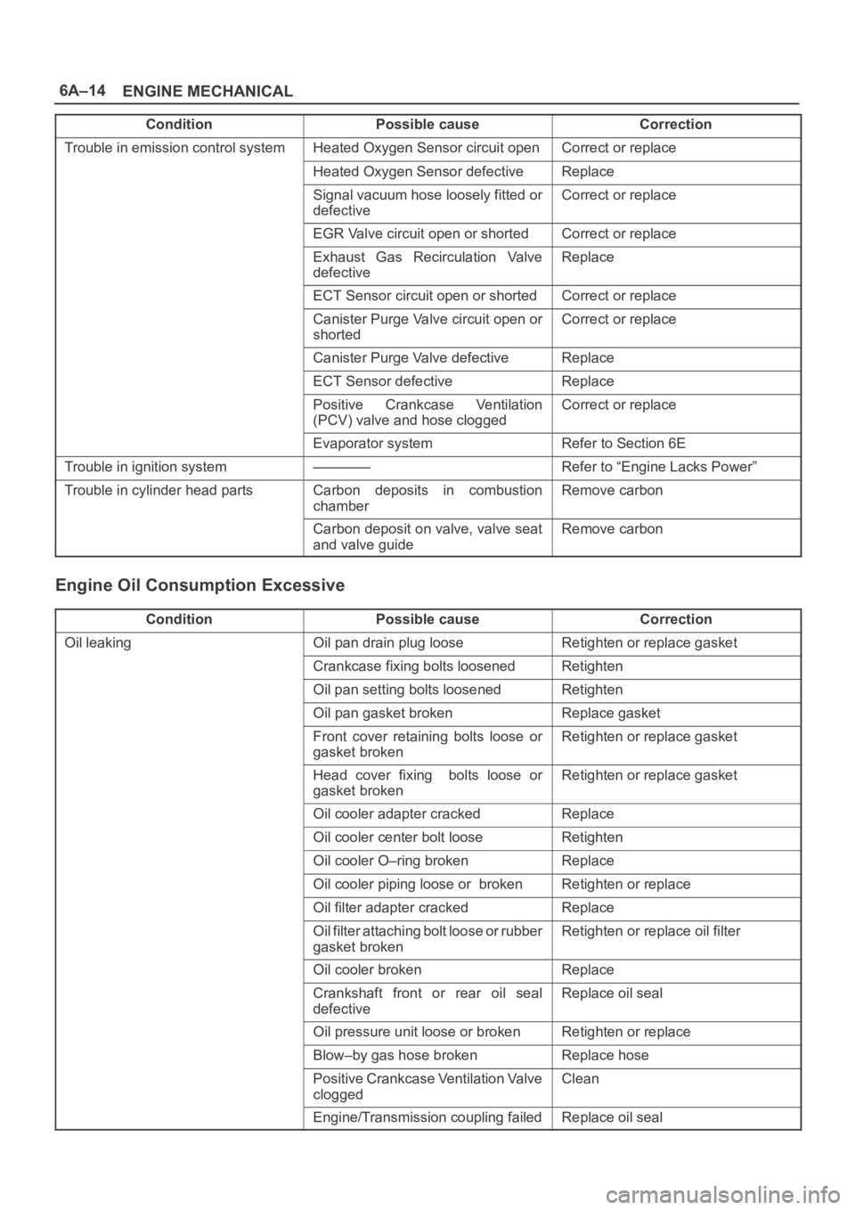
Condition CorrectionPossible cause
Trouble in emission control systemHeated Oxygen Sensor circuit openCorrect or replace
Heated Oxygen Sensor defectiveReplace
Signal vacuum hose loosely fitted or
defectiveCorrect or replace
EGR Valve circuit open or shortedCorrect or replace
Exhaust Gas Recirculation Valve
defectiveReplace
ECT Sensor circuit open or shortedCorrect or replace
Canister Purge Valve circuit open or
shortedCorrect or replace
Canister Purge Valve defectiveReplace
ECT Sensor defectiveReplace
Positive Crankcase Ventilation
(PCV) valve and hose cloggedCorrect or replace
Evaporator systemRefer to Section 6E
Trouble in ignition system————Refer to “Engine Lacks Power”
Trouble in cylinder head partsCarbon deposits in combustion
chamberRemove carbon
Carbon deposit on valve, valve seat
and valve guideRemove carbon
Engine Oil Consumption Excessive
ConditionPossible causeCorrection
Oil leakingOil pan drain plug looseRetighten or replace gasket
Crankcase fixing bolts loosenedRetighten
Oil pan setting bolts loosenedRetighten
Oil pan gasket brokenReplace gasket
Front cover retaining bolts loose or
gasket brokenRetighten or replace gasket
Head cover fixing bolts loose or
gasket brokenRetighten or replace gasket
Oil cooler adapter crackedReplace
Oil cooler center bolt looseRetighten
Oil cooler O–ring brokenReplace
Oil cooler piping loose or brokenRetighten or replace
Oil filter adapter crackedReplace
Oil filter attaching bolt loose or rubber
gasket brokenRetighten or replace oil filter
Oil cooler brokenReplace
Crankshaft front or rear oil seal
defectiveReplace oil seal
Oil pressure unit loose or brokenRetighten or replace
Blow–by gas hose brokenReplace hose
Positive Crankcase Ventilation Valve
cloggedClean
Engine/Transmission coupling failedReplace oil seal
Page 987 of 6000
6A–31
ENGINE MECHANICAL
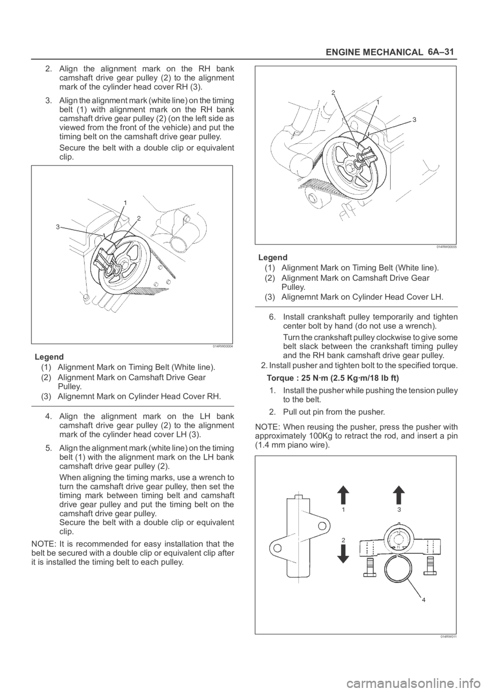
2. Align the alignment mark on the RH bank
camshaft drive gear pulley (2) to the alignment
mark of the cylinder head cover RH (3).
3. Align the alignment mark (white line) on the timing
belt (1) with alignment mark on the RH bank
camshaft drive gear pulley (2) (on the left side as
viewed from the front of the vehicle) and put the
timing belt on the camshaft drive gear pulley.
Secure the belt with a double clip or equivalent
clip.
014RW00004
Legend
(1) Alignment Mark on Timing Belt (White line).
(2) Alignment Mark on Camshaft Drive Gear
Pulley.
(3) Alignemnt Mark on Cylinder Head Cover RH.
4. Align the alignment mark on the LH bank
camshaft drive gear pulley (2) to the alignment
mark of the cylinder head cover LH (3).
5. Align the alignment mark (white line) on the timing
belt (1) with the alignment mark on the LH bank
camshaft drive gear pulley (2).
When aligning the timing marks, use a wrench to
turn the camshaft drive gear pulley, then set the
timing mark between timing belt and camshaft
drive gear pulley and put the timing belt on the
camshaft drive gear pulley.
Secure the belt with a double clip or equivalent
clip.
NOTE: It is recommended for easy installation that the
belt be secured with a double clip or equivalent clip after
it is installed the timing belt to each pulley.
014RW00005
Legend
(1) Alignment Mark on Timing Belt (White line).
(2) Alignment Mark on Camshaft Drive Gear
Pulley.
(3) Alignemnt Mark on Cylinder Head Cover LH.
6. Install crankshaft pulley temporarily and tighten
center bolt by hand (do not use a wrench).
Turn the crankshaft pulley clockwise to give some
belt slack between the crankshaft timing pulley
and the RH bank camshaft drive gear pulley.
2. Install pusher and tighten bolt to the specified torque.
Torque : 25 Nꞏm (2.5 Kgꞏm/18 lb ft)
1. Install the pusher while pushing the tension pulley
to the belt.
2. Pull out pin from the pusher.
NOTE: When reusing the pusher, press the pusher with
approximately 100Kg to retract the rod, and insert a pin
(1.4 mm piano wire).
014RW011
Page 997 of 6000
6A–41
ENGINE MECHANICAL
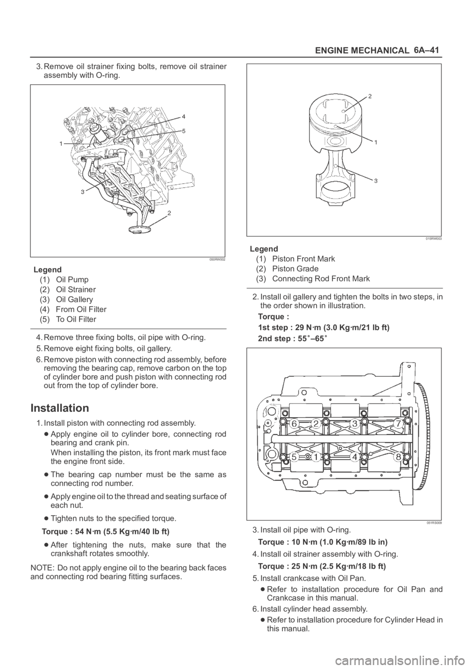
3. Remove oil strainer fixing bolts, remove oil strainer
assembly with O-ring.
050RW002
Legend
(1) Oil Pump
(2) Oil Strainer
(3) Oil Gallery
(4) From Oil Filter
(5) To Oil Filter
4. Remove three fixing bolts, oil pipe with O-ring.
5. Remove eight fixing bolts, oil gallery.
6. Remove piston with connecting rod assembly, before
removing the bearing cap, remove carbon on the top
of cylinder bore and push piston with connecting rod
out from the top of cylinder bore.
Installation
1. Install piston with connecting rod assembly.
Apply engine oil to cylinder bore, connecting rod
bearing and crank pin.
When installing the piston, its front mark must face
the engine front side.
The bearing cap number must be the same as
connecting rod number.
Apply engine oil to the thread and seating surface of
each nut.
Tighten nuts to the specified torque.
Torque : 54 Nꞏm (5.5 Kgꞏm/40 lb ft)
After tightening the nuts, make sure that the
crankshaft rotates smoothly.
NOTE: Do not apply engine oil to the bearing back faces
and connecting rod bearing fitting surfaces.
015RW003
Legend
(1) Piston Front Mark
(2) Piston Grade
(3) Connecting Rod Front Mark
2. Install oil gallery and tighten the bolts in two steps, in
the order shown in illustration.
To r q u e :
1st step : 29 Nꞏm (3.0 Kgꞏm/21 lb ft)
2nd step : 55
–65
051RS009
3. Install oil pipe with O-ring.
Torque : 10 Nꞏm (1.0 Kgꞏm/89 lb in)
4. Install oil strainer assembly with O-ring.
Torque : 25 Nꞏm (2.5 Kgꞏm/18 lb ft)
5. Install crankcase with Oil Pan.
Refer to installation procedure for Oil Pan and
Crankcase in this manual.
6. Install cylinder head assembly.
Refer to installation procedure for Cylinder Head in
this manual.
Page 999 of 6000
6A–43
ENGINE MECHANICAL
6. Remove oil pump assembly.
Refer to removal procedure for Oil Pump in this
manual.
7. Remove cylinder body side bolts.
8. Remove oil gallery.
9. Remove flywheel.
10. Remove rear oil seal retainer.
Refer to removal procedure for Rear Oil Seal in this
manual.
11. Remove connecting rod caps.
12. Remove crankshaft main bearing caps.
13. Remove crankshaft and main bearings.
Installation
1. Install crankshaft and main bearings.
Install main bearing in the cylinder block and main
bearing cap respectively.
Apply new engine oil to upper and lower main
bearings.
NOTE:
Do not apply engine oil to the bearing back faces.
Make sure that main bearings are in correct position.
Install crankshaft with care.
Apply engine oil to the thrust washer.
Install thrust washer on No.3 journal.
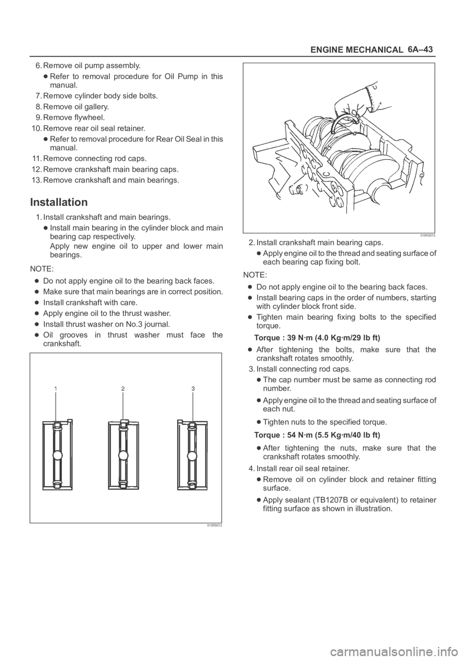
Oil grooves in thrust washer must face the
crankshaft.
015RS012
015RS013
2. Install crankshaft main bearing caps.
Apply engine oil to the thread and seating surface of
each bearing cap fixing bolt.
NOTE:
Do not apply engine oil to the bearing back faces.
Install bearing caps in the order of numbers, starting
with cylinder block front side.
Tighten main bearing fixing bolts to the specified
torque.
Torque : 39 Nꞏm (4.0 Kgꞏm/29 lb ft)
After tightening the bolts, make sure that the
crankshaft rotates smoothly.
3. Install connecting rod caps.
The cap number must be same as connecting rod
number.
Apply engine oil to the thread and seating surface of
each nut.
Tighten nuts to the specified torque.
Torque : 54 Nꞏm (5.5 Kgꞏm/40 lb ft)
After tightening the nuts, make sure that the
crankshaft rotates smoothly.
4. Install rear oil seal retainer.
Remove oil on cylinder block and retainer fitting
surface.
Apply sealant (TB1207B or equivalent) to retainer
fitting surface as shown in illustration.
Page 1004 of 6000
6A–48
ENGINE MECHANICAL
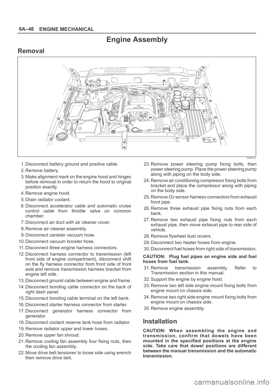
Engine Assembly
Removal
035RW027
1. Disconnect battery ground and positive cable.
2. Remove battery.
3. Make alignment mark on the engine hood and hinges
before removal in order to return the hood to original
position exactly.
4. Remove engine hood.
5. Drain radiator coolant.
6. Disconnect accelerator cable and automatic cruise
control cable from throttle valve on common
chamber.
7. Disconnect air duct with air cleaner cover.
8. Remove air cleaner assembly.
9. Disconnect canister vacuum hose.
10. Disconnect vacuum booster hose.
11. Disconnect three engine harness connectors.
12. Disconnect harness connector to transmission (left
front side of engine compartment), disconnect shift
on the fly harness connector from front side of front
axle and remove transmission harness bracket from
engine left side.
13. Disconnect ground cable between engine and frame.
14. Disconnect bonding cable connector on the back of
right dash panel.
15. Disconnect bonding cable terminal on the left bank.
16. Disconnect starter harness connector from starter.
17. Disconnect generator harness connector from
generator.
18. Disconnect coolant reserve tank hose from radiator.
19. Remove radiator upper and lower hoses.
20. Remove upper fan shroud.
21. Remove cooling fan assembly four fixing nuts, then
the cooling fan assembly.
22. Move drive belt tensioner to loose side using wrench
then remove drive belt.23. Remove power steering pump fixing bolts, then
power steering pump. Place the power steering pump
along with piping on the body side.
24. Remove air conditioning compressor fixing bolts from
bracket and place the compressor along with piping
on the body side.
25. Remove O
2 sensor harness connectors from exhaust
front pipe.
26. Remove three exhaust pipe fixing nuts from each
bank.
27. Remove two exhaust pipe fixing nuts from each
exhaust pipe, then move exhaust pipe to rear side of
vehicle.
28. Remove flywheel dust covers.
29. Disconnect two heater hoses from engine.
30. Disconnect fuel hoses from right side of transmission.
CAUTION: Plug fuel pipes on engine side and fuel
hoses from fuel tank.
31. Remove transmission assembly. Refer to
Transmission section in this manual.
32. Support the engine by engine hoist.
33. Remove two left side engine mount fixing bolts from
engine mount on chassis side.
34. Remove two right side engine mount fixing bolts from
engine mount on chassis side.
35. Remove engine assembly.
Installation
CAUTION: W h e n a s s e m b l i n g t h e e n g i n e a n d
transmission, confirm that dowels have been
mounted in the specified positions at the engine
side. Take care that dowel positions are different
between the manual transmission and the automatic
transmission.
Page 1005 of 6000

6A–49
ENGINE MECHANICAL
If the engine is assembled in the condition that the
dowels have not been mounted in the specified posi-
tions, the transmission may be damaged the trans-
mission.
012RS009
1. Install engine assembly. Tighten engine mount fixing
bolts to frame to the specified torque.
Torque: 41 Nꞏm (4.2 Kgꞏm/30 lb ft)
2. Reconnect fuel hose to fuel pipe on engine.
3. Install transmission assembly. Refer to Transmission
section in this manual.
4. Reconnect two heater hoses to engine.
5. Install flywheel dust covers.
6. Install exhaust pipe and temporally tighten two (each
bank) rear exhaust flange nuts then tighten three stud
nuts (each bank) between exhaust manifold and
exhaust pipe, finally tighten rear side nuts to the
specified torque.
Torque:
Nuts: 43 Nꞏm (4.4 Kgꞏm/32 lb ft)
Stud nuts: 67 Nꞏm (6.8 Kgꞏm/49 lb ft)
150RW061
Legend
(1) Exhaust Front Pipe RH
(2) O
2 Sensor (for IGM)
150RW062
Legend
(1) Exhaust Front Pipe LH
7. Reconnect O2 sensor connector.
8. Install cooling fan assembly and tighten bolts/nuts to
the specified torque.
Torque : 22 Nꞏm (2.2 Kgꞏm/16 lb ft) for fan pulley
and fan bracket.
Torque : 10 Nꞏm (1.0 Kgꞏm/88.5 lb in) for fan and
clutch assembly.