Front ach OPEL FRONTERA 1998 Repair Manual
[x] Cancel search | Manufacturer: OPEL, Model Year: 1998, Model line: FRONTERA, Model: OPEL FRONTERA 1998Pages: 6000, PDF Size: 97 MB
Page 2390 of 6000

7B–72MANUAL TRANSMISSION
Special Tools
ILLUSTRATIONTOOL NO.
TOOL NAME
5–8840–2550–0
(J–42794)
Gear spline pieace
remover
5–8840–2551–0
(J–42795)
Center bearing remover
5–8840–2560–0
(J–42988)
Attachment
5–8840–2552–0
(J–42796)
Counter gear shaft
center bearing installer
5–8840–2553–0
(J–42797)
Clutch hub (No.2)
installer
5–8840–2554–0
(J–42798)
Clutch hub (No.1)
installer
ILLUSTRATIONTOOL NO.
TOOL NAME
5–8840–2555–0
(J–42799)
Installer
5–8840–2556–0
(J–42800)
Counter gear shaft front
bearing installer
5–8840–2559–0
(J–42904)
Top gear shaft front
bearing installer
5–8840–2557–0
(J–42801)
Front rerainer oil seal
installer
5–8840–2558–0
(J–42802)
Transfer adapter oil seal
installer
5–8840–0007–0
(J–8092)
Driver handle
Page 2524 of 6000

CLUTCH7C–15
Installation
To install, follow the removal steps in the reverse order,
noting the following points:
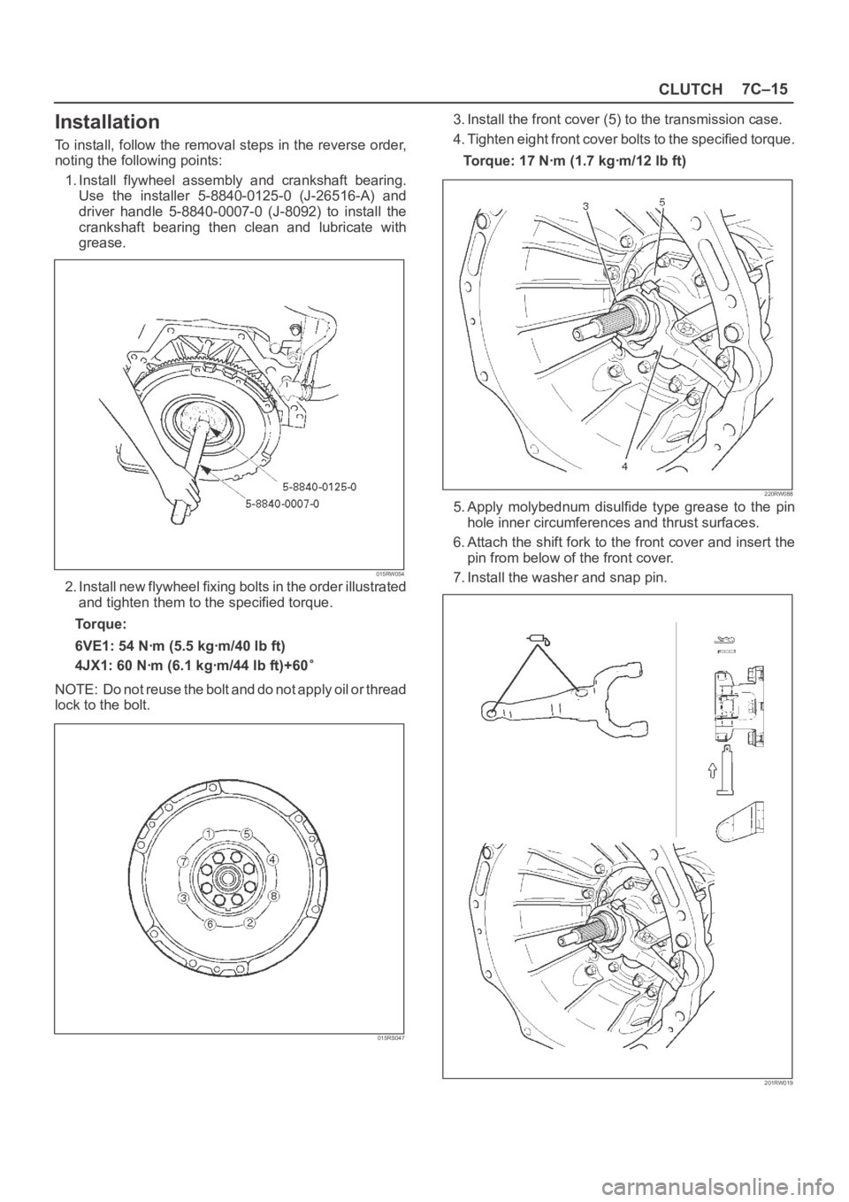
1. Install flywheel assembly and crankshaft bearing.
Use the installer 5-8840-0125-0 (J-26516-A) and
driver handle 5-8840-0007-0 (J-8092) to install the
crankshaft bearing then clean and lubricate with
grease.
015RW054
2. Install new flywheel fixing bolts in the order illustrated
and tighten them to the specified torque.
Torque:
6VE1: 54 Nꞏm (5.5 kgꞏm/40 lb ft)
4JX1: 60 Nꞏm (6.1 kgꞏm/44 lb ft)+60
NOTE: Do not reuse the bolt and do not apply oil or thread
lock to the bolt.
015RS047
3. Install the front cover (5) to the transmission case.
4. Tighten eight front cover bolts to the specified torque.
Torque: 17 Nꞏm (1.7 kgꞏm/12 lb ft)
220RW088
5. Apply molybednum disulfide type grease to the pin
hole inner circumferences and thrust surfaces.
6. Attach the shift fork to the front cover and insert the
pin from below of the front cover.
7. Install the washer and snap pin.
201RW019
Page 3179 of 6000

8E–2METER AND GAUGE
Meter Assembly
General Description
The meter assembly has the speedometer, tachometer,
engine coolant temperature gauge, fuel gauge and
warning/indicator lights. In addition, the meter assembly
containing TOD (Torque on Demand) has the TOD
indicator light, or the meter assembly not containing TOD
has the voltmeter and oil pressure gauge instead of the
TOD indicator.
Layout for Meters/Gauges, Warning Lights, Indicator Lights and Illumination
Lights
Meter Assembly–Gasoline W/O TOD (Front View)
825RW207
Legend
(1) Voltmeter & Engine Coolant Temperature
Gauge
(2) Tachometer
(3) Warning Light Lens
(4) Speedometer(5) Oil Pressure Gauge & Fuel Gauge
(6) Warning Light Lens
(7) Reset Knob
(8) A/T Shift Indicator
(9) Warning Light Lens
Page 3181 of 6000

8E–4METER AND GAUGE
Meter Assembly–Gasoline W/TOD (Front View)
825RW210
Legend
(1) TOD Indicator
(2) Tachometer
(3) Warning Light Lens
(4) Speedometer(5) Coolant Temperature Gauge & Fuel Gauge
(6) Warning Light Lens
(7) Reset Knob
(8) A/T Shift Indicator
(9) Warning Light Lens
Page 3183 of 6000

8E–6METER AND GAUGE
Meter Assembly–Diesel (Front View)
825RW211
Legend
(1) TOD Indicator
(2) Tachometer
(3) Warning Light Lens
(4) Speedometer(5) Coolant Temperature Gauge & Fuel Gauge
(6) Warning Light Lens
(7) Reset Knob
(8) Warning Light Lens
Page 3188 of 6000

METER AND GAUGE8E–11
Meter Assembly–Gasoline W/TOD–2
Connector No. I–9
Te r m i n a lFunction
1—
2Air bag warning light
3A/T oil temp warning light
4Charge warning light
5Check engine warning light
6Check trans warning light
7Brake warning light
8—
9Tachometer
10—
11Turn signal indicator light (Left)
12A/T shift indicator control unit
132 position (A/T)
14D position (A/T)
15Rear (TOD)
16Auto (TOD)
17Check (TOD)
18Cruise set indicator light
19Cruise main indicator light
20Oil pressure warning light
21Front “1” (TOD)
22Front “2” (TOD)
23Front “3” (TOD)
24Cigarette lighter illumination light
25Illumination controller
26Starter switch
27—
28Winter drive indicator light
29Power drive indicator light
30—
Connector No. I–10
Te r m i n a lFunction
1Turn signal indicator light (Right)
2L position (A/T)
3R position (A/T)
4Check engine warning light
5Speedometer
6—
7—
8Battery (+)
9Engine coolant temperature gauge
10Ground
11P position (A/T)
12N position (A/T)
133 position (A/T)
14High beam indicator light (–)
15High beam indicator light (+)
16ABS indicator light
17—
18Fuel warning light
19—
20Fuel gauge
21Ground (Gauge)
22—
Page 3201 of 6000

8F–6BODY STRUCTURE
General Description
This section describes how to remove and install front
and rear bumpers. Each bumper is installed with two
fixing bolts used on either side to fasten the backbar to theframe, a slider is used to fasten the bumper fascia to the
fender panel. The bumpers can be removed by taking
them out forward or backward after removing the two
fixing bolts on either side.
Front Bumper
Parts Location
601RW015
Legend
(1) Front Bumper Retainer Bolt
(2) Front Bumper Assembly
(3) Support Fixing Clip
(4) Bumper Spacer Support
(5) Back Bar Fixing Bolt
(6) Front Fog Light Connector
(7) Front Bumper Slider Fixing Clip(8) Front Bumper Slider
(9) Front Bumper Slider Fixing Nut
(10) Bumper Fascia Lower Bolt
(11) Front Fog Light Assembly
(12) Reinforce Assembly
(13) Reinforce Lower Bolt
(14) Front Bumper Fixing Bolt
Page 3202 of 6000

8F–7 BODY STRUCTURE
Removal
1. Disconnect battery ground cable.
2. Remove front fog light connector.
3. Remove front bumper assembly fixing bolt.
Remove the two bolts from both sides of the front
bumper.
601RW010
4. Remove front bumper assembly.
5. Remove bumper fascia lower bolts.
6. Remove front bumper retainer.
7. Remove reinforce lower bolts.
Loosen the five bolts and release claws.
8. Remove reinforce assembly.9. Remove backbar fixing bolts.
Remove the four bolts at each backbar.
10. Remove front fog light assembly.
11. Remove the front bumper slider(1).
Remove the two clips(4) and the two nuts(3), and
release the claw from the washer(2).
601RW009
Installation
To install, follow the removal steps in reverse order noting
the following points:
1. Tighten the front bumper assembly fixing bolts to the
specified torque.
To r q u e : 1 3 2 N
m (13.5kgꞏm/98 lb ft)
Front Bumper Slider Bracket
Removal
1. Disconnect battery ground cable.
2. Remove the Front bumper.
Refer to Front Bumper in this section.
3. Remove the three nuts(1) and draw out the slider
bracket(2).
601RW003
Installation
To install, follow the removal steps in reverse order.
Page 3210 of 6000

8F–15 BODY STRUCTURE
General Description
This section includes items of front end sheet metal that
are attached by bolts, screws or clips and related
accessory components.Anti-corrosion materials have been applied to the interior
surfaces of some metal panels to provide rust resistance.
When servicing these panels, areas on which this
material has been disturbed should be properly recoated
with service-type anti-corrosion material.
Cowl Cover
Parts Location
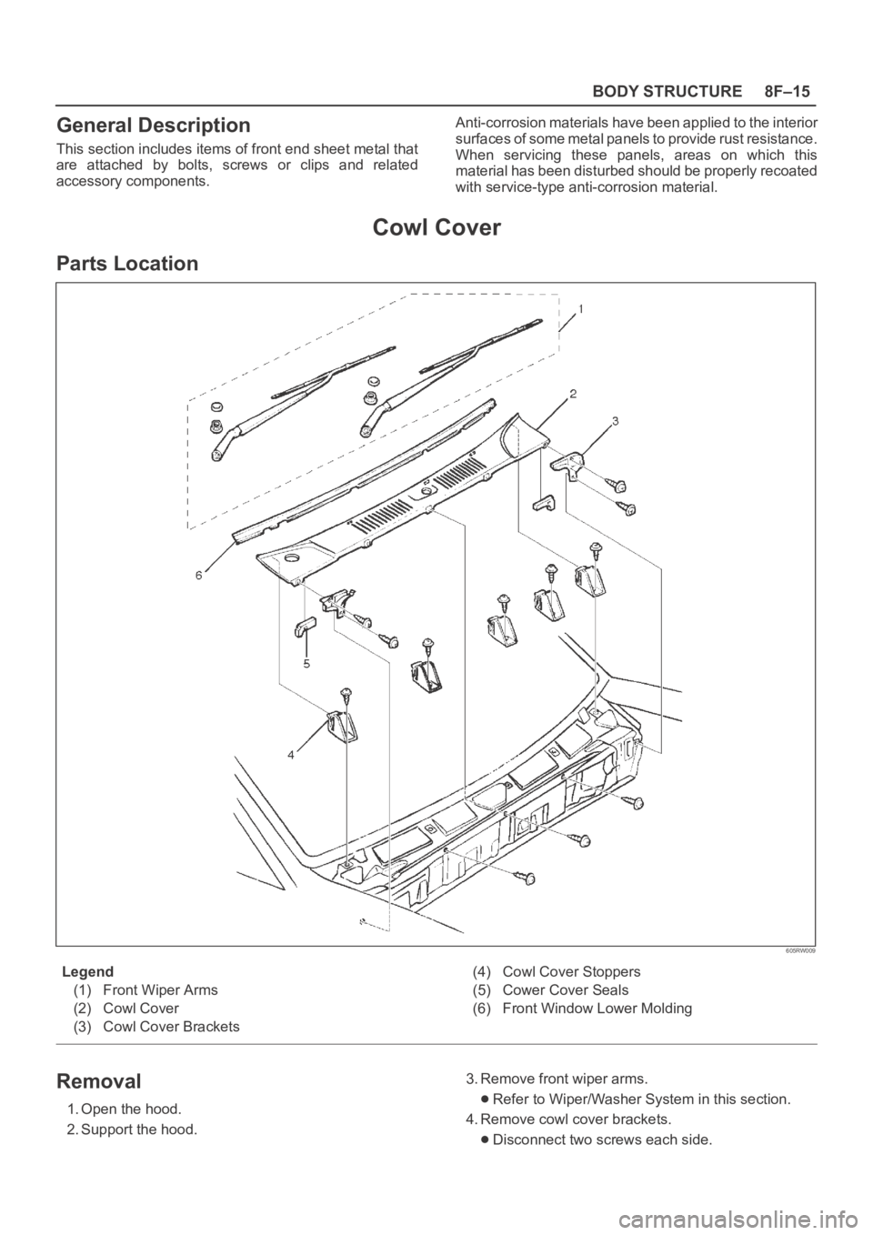
605RW009
Legend
(1) Front Wiper Arms
(2) Cowl Cover
(3) Cowl Cover Brackets(4) Cowl Cover Stoppers
(5) Cower Cover Seals
(6) Front Window Lower Molding
Removal
1. Open the hood.
2. Support the hood.3. Remove front wiper arms.Refer to Wiper/Washer System in this section.
4. Remove cowl cover brackets.
Disconnect two screws each side.
Page 3248 of 6000

8F–53 BODY STRUCTURE
Installation
To install, follow the removal steps in the reverse order.
Order Of Removal/Installation Steps For Each Item
Removal Item
Removal ProcedureRemoval Step
Front console assem-
blyShift knob (M/T), Power & Winter SW (A/T), Transfer knob, Seat
heater/Miller SW conn. and 4 screws1, 2
Lower cluster assem-
bly3 screws, Ciger lighter conn. and Ashtray illumination conn.13
Glove box2 screws4
Instrument panel pas-
senger lower cover7 screws and 1 clip15
Passenger knee bol-
ster reinforcement4 nuts and 4 bolts16
Instrument panel driver
lower coverEngine hood opening fixing screw, 2 screws, 1 bolt, 1 clip and fasten-
ers at 4 positions13, 7
Driver knee bolster6 nuts13, 7, 8
Front defroster grilleClaws at 8 positions9
Instrument panel as-
sembly2 bolts (SRS adjust bracket cross beam), A/C control cable (Unit
side at 3 position), Instrument harness connector (Driver side 5 posi-
tion, assist side 3 position), SRS module conn., Radio antenna jack,
Earth cable, 9 bolts and 3 nuts110
Passenger inflator
module4 nuts (SRS moduleInstrument panel), 2 nuts 0 and 2 washers
(SRS module
support bracket) and 2 clips
16, 11
Instrument panel clus-
ter5 Screws, fastener at 4 position and each SW conn.13, 7, 12
Meter assembly4 screws and connectors13, 7, 12, 13
A/C control panel as-
sembly4 screws and connectors13, 7, 12, 14
Radio assembly2 screws13, 15
Vent duct assembly5 screws110, 16
Instrument harness as-
sembly4 screws, fasteners at 4 position, and clips at 7 position110, 17
Side defroster grille18
M/T = Manual Transmission
A/T = Automatic Transmission
SRS = Supplemental Restraint System
A/C = Air Conditioning