relay OPEL FRONTERA 1998 Manual Online
[x] Cancel search | Manufacturer: OPEL, Model Year: 1998, Model line: FRONTERA, Model: OPEL FRONTERA 1998Pages: 6000, PDF Size: 97 MB
Page 1487 of 6000

6G–8
ENGINE LUBRICATION
3. Install crankcase, tighten crankcase fixing bolts
to the specified torque.
Torque : 10 Nꞏm (1.0 Kgꞏm/89 lb in)
013RW004
2. Install oil pan
1. Remove residual sealant, lubricant and moisture
from mounting surface, then dry thoroughly.
2. Properly apply a 4.5 mm (07 in) wide bead of
sealant (TB-1207C or equivalent) to mounting
surface of oil pan.
Sealant beat must be continuous.
The crankcase must be installed within 5
minutes after sealant application befor the
sealant hardens.
013RW003
3. Install oil pan, tighten oil pan fixing bolts to the
specified torque.
Torque : 25 Nꞏm (2.5 Kgꞏm/18 lb ft)3. Install axle housing assembly and tighten fixing bolts
to the specified torque.
Axle case bolts
Torque : 82 Nꞏm (8.4 Kgꞏm/60 lb ft)
Mounting bolts
Torque : 152 Nꞏm (15.5 Kgꞏm/112 lb ft)
013RW005
4. Install relay lever assembly and tighten fixing bolts.
Torque: 44 Nꞏm (4.5 Kgꞏm/32 lb ft)
5. Engage teeth of pitman arm and steering unit, and
tighten nut to the specified torque.
Torque : 216 Nꞏm (22.0 Kgꞏm/159 lb ft)
013RW006
Legend
(1) Pitman Arm
(2) Relay Lever
Page 1720 of 6000

ST
ON
OFF
ON
OFF
ON
OFF
ON
OFF
18Km/h
9km/h
ON
OFF
ON
OFF
ON
OFF Starter SW
Starter SW is turned to
“ST” before indicator light
goes out.Starter SW is turned to
“ST” after indicator light
goes out.Starter SW
is left “ON”
Indicator timer
After glow timer
Charge relay
Indicator light
Relay 1
Relay 2Above
Vehicle speed below
t i t i t i
t a t a
t d t d t d t d
Glow plug
temperature
0t 0t 0t
: Indicator light “ON” time
: Rapid after glow (Delay timer) time
: After glow time
ti
td
ta
(For broken lines,
water temperature
is 70
C or above)
Page 1746 of 6000

ENGINE MECHANICAL 6A – 13
VALVE CLEARANCE ADJUSTMENT
1. Install 2.80 mm valve adjuster (shim) first when
reassembling the engine.
Thickness mark faces down.
2. Measure the valve clearance after installing cam
carrier assy with camshafts.
3. Change the adjuster using a special tool when the
clearance is out of tolerance.
Valve Clearance Adjusting Tool: 5-8840-2590-0
VALVE CLEARANCE (When cold condition)
Inlet 0.15 ± 0.05 mm
Exh 0.25 ± 0.05 mm
COMPRESSION PRESSURE
MEASUREMENT
1. Start the engine and allow it to idle until the coolant
temperature reaches 70 – 80°C (158 – 176°F).
2. Remove the following parts.
Glow plugs
Fuel cut solenoid connector
QOS (Quick-On Start System) fuse in the fuse
box.
3. Set the adapter and compression gauge to the No.
1 cylinder glow plug hole.
Compression Gauge
(with Adapter): 5-8840-2008-0
4. Turn the engine over with the starter motor and take
the compression gauge reading.
Compression Pressure at 200 rpm
Standard: 3040 kPa (31 kg/cm
2/441 psi)
Limit: 2160 kPa (22 kg/cm
2/313 psi)
5. Repeat the procedure (Steps 3 and 4) for the
remaining cylinders.
QUICK-ON START 4 SYSTEM
Quick-On Start System Inspection Procedure
1. Disconnect the ECT-sensor connection around the
thermostat outlet pipe.
2. Turn the starter switch to the “ON” position.
If the Quick-On Start 4 System is operating
properly, the glow relay will make a clicking sound
within seven seconds after the starter switch is
turned on.
3. Measure the glow plug terminal voltage with a
circuit tester immediately after turning the starter
switch to the “ON” position.
Glow Plug Terminal Voltage: approx. 12V
NOTE: Electrical power to the quick-on start system will
be cut after the starter has remained in the “ON”
position for twenty seconds.
Turn the starter switch to the “OFF” position and back
to the “ON” position.
This will reset the Quick-On Start 4 System.
014RW150
Page 1872 of 6000

ENGINE ELECTRICAL 6D – 5
STARTING SYTEM
GENERAL DESCRIPTION
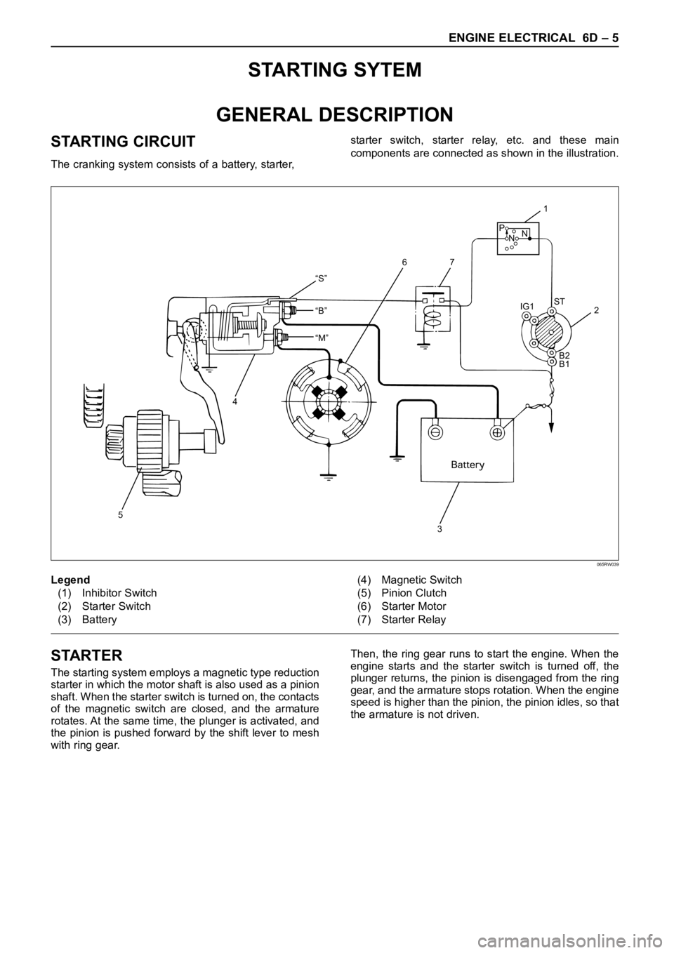
STARTING CIRCUIT
The cranking system consists of a battery, starter, starter switch, starter relay, etc. and these main
components are connected as shown in the illustration.
“S”
“B”
“M”
5
4
32 IG1ST
B2
B1
1
76
P
NN
Legend
(1) Inhibitor Switch
(2) Starter Switch
(3) Battery(4) Magnetic Switch
(5) Pinion Clutch
(6) Starter Motor
(7) Starter Relay
065RW039
STARTER
The starting system employs a magnetic type reduction
starter in which the motor shaft is also used as a pinion
shaft. When the starter switch is turned on, the contacts
of the magnetic switch are closed, and the armature
rotates. At the same time, the plunger is activated, and
the pinion is pushed forward by the shift lever to mesh
with ring gear.Then, the ring gear runs to start the engine. When the
engine starts and the starter switch is turned off, the
plunger returns, the pinion is disengaged from the ring
gear, and the armature stops rotation. When the engine
speed is higher than the pinion, the pinion idles, so that
the armature is not driven.
Page 1873 of 6000

6D – 6 ENGINE ELECTRICAL
RELATION BETWEEN STARTER SWITCH AND STARTER
M
Key
PositionB1 B2 ACCIG1 IG2 ST
LOCKKey
Removed
Inserted OFF
ACC
ON
START
BSBattery
+-
2
17
3
4
5
6
Legend
(1) Starter Switch
(2) To Generator
(3) To QOS4 Control(4) Starter Relay
(5) Immobilizer Relay (for Europe)
(6) Magnetic Switch
(7) Battery
065R200029
Page 1874 of 6000

ENGINE ELECTRICAL 6D – 7
ON-VEHICLE SERVICE
STARTER
REMOVAL
1 Battery ground cable
2 Remove the slave cylinder and bind with wire it to
the frame.
3 Disconnect the connector from terminals “B” and
“S”.
4. Remove mounting bolts
5. Remove starter assembly
INSTALLATION
1. Install starter assembly, tighten the fixing bolt and
nut to the specified torque.
Torque: 94 Nꞏm (9.6 kgꞏm/69 lb ft)
2. Reconnect the starter terminals.
CAUTION: When installing the starter motor wiring,
do not allow the S-circuit wiring to obstruct the B-
circuit terminal.
Install the wiring exactly as shown on the attached
illustration.
If S-circuit wiring obstructs the B-circuit terminal,
harness cover breakage and short circuiting may
occur.2-1. Install the wire harness from the battery to the
terminal “B” with tightening torque 8.6 Nꞏm
(0.88 kgꞏm/6.4 lbꞏft).
2-2. Cover the terminal “B” together with wire
harness.
2-3. Connect the wire harness from starter relay to
the terminal “S”.
3. Install the clutch slave cylinder, tighten the fixing
bolt and nut to the specified torque.
Torque: 78 Nꞏm (8.0 kgꞏm/58 lbꞏft)
1
32
4
Legend
(1) Clutch Slave Cylinder
(2) Magnetic Switch(3) Bolt
(4) Starter Assembly
065RW00003
Do not recommend
wiring route.
Recommend wiring route
from S terminal.From
battery
From
starter relay Terminal B
Terminal MTerminal SIn this area,
Scratch to break the wire
cover and make shortage.
065RW00002
Page 1882 of 6000

ENGINE ELECTRICAL 6D – 15
CHARGING SYSTEM
GENERAL DESCRIPTION
GENERATOR
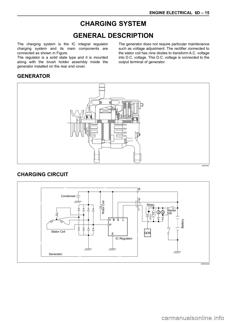
CHARGING CIRCUIT
The charging system is the IC integral regulator
charging system and its main components are
connected as shown in Figure.
The regulator is a solid state type and it is mounted
along with the brush holder assembly inside the
generator installed on the rear end cover.The generator does not require particular maintenance
such as voltage adjustment. The rectifier connected to
the stator coil has nine diodes to transform A.C. voltage
into D.C. voltage. This D.C. voltage is connected to the
output terminal of generator.
A06RW001
Condenser
GeneratorStator Coil
IC RegulatorStarter
SW
Rotor Coil
Battery
P F
EBS LRelay B
S
L
QOS
065R200028
Page 1883 of 6000

6D – 16 ENGINE ELECTRICAL
DIAGNOSIS
GENERAL ON-VEHICLE INSPECTION
The operating condition of the charging system is
indicated by the charge warning lamp. The warning
lamp comes on when the starter swtich is turned to
“ON” position. The charging system operates normallyif the lamp goes off when the engine starts. If the
warning lamp shows abnormality or if undercharged or
overcharged battery condition is suspected, perform
diagnosis by checking the charging system as follows:
Condenser
GeneratorStator Coil
IC RegulatorStarter
SW
Rotor Coil
Battery
P F
EBS LRelay B
S
L
QOS
065R200028
1. Check visually the belt and wiring connector.
2. With the engine in stop status, turn the starter
switch to “ON” position and observe the warning
lamp.
1) If lamp does not come on:
Disconnect wiring connector from generator,
and ground terminal “L” on connector side.
2) If lamp comes on:
Repair or replace the generator.
Page 1890 of 6000

ENGINE ELECTRICAL 6D – 23
QOS4 PREHEATING SYSTEM
GENERAL DESCRIPTION
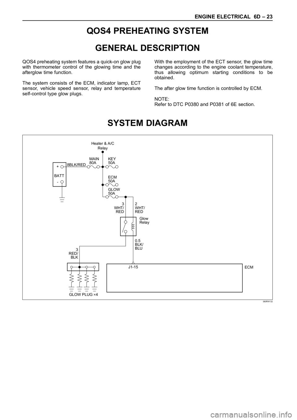
QOS4 preheating system features a quick-on glow plug
with thermometer control of the glowing time and the
afterglow time function.
The system consists of the ECM, indicator lamp, ECT
sensor, vehicle speed sensor, relay and temperature
self-control type glow plugs.With the employment of the ECT sensor, the glow time
changes according to the engine coolant temperature,
thus allowing optimum starting conditions to be
obtained.
The after glow time function is controlled by ECM.
NOTE:
Refer to DTC P0380 and P0381 of 6E section.
SYSTEM DIAGRAM
+
-KEY
50A
ECM
50A
GLOW
50A
2
WHT/
RED
0.5
BLK/
BLU
ECM J1-15 3
WHT/
RED
3
RED/
BLKMAIN
80A
8BLK/RED
Glow
Relay
GLOW PLUG 4
BATTHeater & A/C
Relay
060RW132
Page 1891 of 6000

6D – 24 ENGINE ELECTRICAL
1 Inspection on Quick Heating Operation
1. Disconnect ECT-sensor connection on the
thermostat housing
Legend
(1) ECT Sensor
(2) EVRV
2. Connect the circuit tester between glow plug and
engine earth.
3. Inspect the following items with starter switch set to
ON position (but do not start the engine).
1) The glow indicator shall light for about 5 sec.
2) The circuit tester shall indicate power supply
voltage for 180 sec.
If above specifications are not satisfied, inspect
wire harness, glow relay and ECT-sensor. If
satisfied, inspect glow plug.2 Inspection on Afterglow Operation
1. Disconnect ECT-sensor connection on the
thermostat housing
Legend
(1) ECT Sensor
(2) EVRV
2. Connect the circuit tester between glow plug and
engine earth.
3. Inspect the following item with the engine started.
1) The circuit tester shall indicate about 12 volts
after 180 seconds of engine start.
If above specifications are not satisfied, inspect
battery voltage, engine earth, wiring harness,
glow plug, and ECM.
12
060RW166
065RW035
12
060RW166
065RW035
INSPECTION ON QOS4 SYSTEM OPERATION