PONTIAC FIERO 1988 Service Repair Manual
Manufacturer: PONTIAC, Model Year: 1988, Model line: FIERO, Model: PONTIAC FIERO 1988Pages: 1825, PDF Size: 99.44 MB
Page 461 of 1825
6D2-10 CRANKING SYSTEM
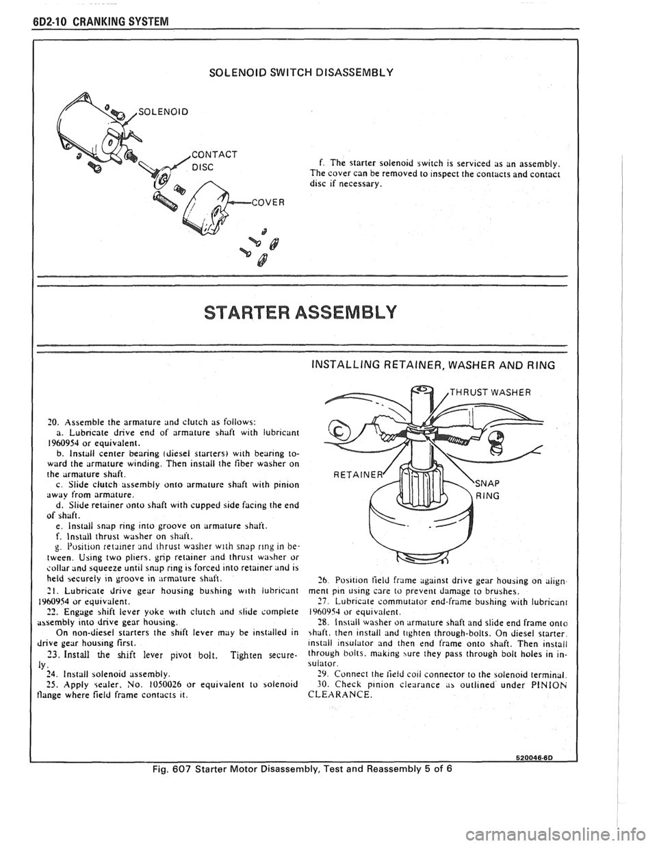
SOLENOID SWITCH DISASSEMBLY
I
COVER
3
f. The starter solenoid switch is servlced as an assembly.
The cover can be removed to Inspect the contacts and contact dlsc rf necessary.
STARTER ASSEMBLY
INSTALLING RETAINER, WASHER AND RING
1 THRUST WASHER
I 20. Assemble the armature and clutch as follows:
a. Lubricate dnve end of armature shaft w~th lubricant
1960954 or equ~valent. b. Install center bearrng (dresel starters) wrth bear~ng to-
ward the armature w~nd~ng. Then install the fiber washer on
the armature shaft
c Slide clutch assembly onto armature shaft
w~th plnlon dwdy from armature.
d. Sllde retainer onto shaft w~th cupped 51de facing the end
of shaft.
e
Install snap rrng Into groove on armature >haft. f. Install thrust washer on bhaft.
g I'os~t~on retmer ~nd thrust washer with snap rlng in be-
tween Usrng two pl~ers, gnp retalner ~nd thrust washer or sollar and bqueeze unt~l snap rrng 15 forced Into retainer and 15 held becurely In groove rn ,
mature shaft. 26 Po5111on field frame agarnst drrve gear houb~ng on alrgn 21. Lubr~cate dr~ve gear housrng bush~ng w~th lubricant ment pln uslng care to prevent damage to brushes.
1960954 or equtvalent. 27 Lubrrcate commutator end-frame bush~ng wrth lubncan~ 22. Engage shift lever yoke w~th clutch and jlrde complete 1960954 or equ~vnlent assembly Into dnve gear houb~ng. 28 Install washer on armature >haft and sl~de end frame onto
On non-diesel starters the sh~ft lever may be ~nslalled In \haft, then ~nstall and t~ghten through-bolts. On d~esel starter
drrve gear houslng first. ~nstall ~nsulator and then end frame onto shaft. Then ~nstall
23. Install the shift lever p~vot bolt. Tighten secure. through bolts. maklng jure they pass through bolt holes In In-
IY. sulator
24 Install solenold assembly. 29 Connect the tirld co11 connector to the solenold term~nal 25. Apply \ealrr. No. 1050026 or equ~valent to bolenold 30. Check plnron clearance ,I> outi~ned under PlNlOh flange where field frame contacts 11. CLEARANCE.
520046.6D
Fig. 607 Starter Motor Disassembly, Test and Reassembly 5 of 6
Page 462 of 1825
CRANKING SYSTEM BD2-11
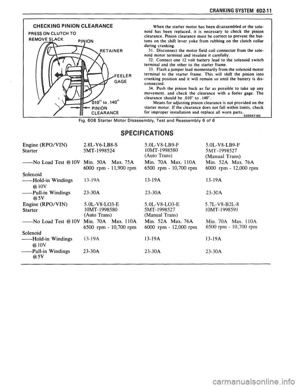
CHECKING PINION CLEARANCE When the starter motor has been disassembled or the sole-
PRESS ON CLUTCH TO noid has been replaced, it is necessary to check the pinion
clearance. Pinion clearance must be correct to prevent the but-
tons on the shift lever yoke from rubbing on the clutch collar
during cranking.
3 1. Disconnect the motor field coil connector from the sole-
noid motor terminal and insulate it carefully.
32. Connect one 12 volt battery lead to the solenoid switch
terminal and the other to the starter frame.
33. Flash a jumper lead momentarily from the solenoid motor
FEEL^^ terminal to the starter frame. This will shift the pinion into
cranking position and it will remain so until the battery is dis-
connected.
34. Push the pinion back as far as possible to take up any
movement. and check the clearance with a feeler gage. The
clearance should be
.01OV to .140.
Means for adjusting pinion clearance is not provided on the
starter motor. If the clearance does not fall within limits, check
for improper installation and replace all worn parts.
520047-6D
Fig. 608 Starter Motor Disassembly, Test and Reassembly 6 of 6
Engine (RPO/VIN) 2.8L-V6-LB8-%
Starter 5MT-1998524
-No Load Test
@ 10V Min. 50A Max. 75A
6000 rprn
- 1 1,900 rpm
Solenoid
-Hold-in Windings
13- 19A
@ IOV
----Pull-in Windings 23-30A
@ 5v
Engine (RPO/VIN) 5.OL-V8-L03-E
Starter IOMT-1998580
(Auto Trans)
No Load Test
@ 10V Min. 70A Max. 1 lOA
6500 rpm - 10,700 rprn
Solenoid
-Hold-in Windings
13- 19A
@ 1ov
-Pull-in Windings 23-30A
@ 5v
5 .OL-V8-LB9-F
IOMT- 1998580
(Auto Trans)
Min. 70A Max.
1 lOA
6500 rpm - 10,700 rprn
5
.OL-V8-L03-E
5MT- I998527
(Manual Trans)
Min. 52A Max. 76A
6000 rprn
- 12,000 rprn
5.OL-V8-LB9-F
5MT-1998527
(Manual Trans)
Min. 52A Max. 76A
6000 rprn
- 12,000 rprn
Min. 70A Max.
1 lOA
6500 rpm - 10,700 rpm
Page 463 of 1825

Page 464 of 1825
CHARGING SYSTEM 6D3-1
SECTION 6D3
CHARG NG SYSTEM
CONTENTS
General Description ................................. 6D3- 1 Charging System ........................................ 6D3- 1
.......................................... Charging System - CS ............................... 6D3- 1 On-Car Service 6D3-2
................................................... Diagnosis .. 6D3- 1 Generator 6D3-3 ...................... ......................... ............................................. 6D3- 1 Specifications 6D3-3 Service Procedures .................................. Unit Repair .. 6D3-4-6 ............................... ............
GENERAL DESCRIPTION
The engine electrical system includes the battery,
ignition (primary and secondary), starter (and related
wiring) and the generator (and related wiring).
Diagnostic charts (see Section 6D) will aid in
trouble-shooting system faults. When a fault is traced
to a particular component, refer to that components'
section of the service manual.
CHARGING SYSTEM-CS
The CS Charging System has several sizes
available, including the CS-130 and CS-144. The
number (130 or 144) denotes the
OD in mm of the
stator laminations.
CS generators use a new type regulator and a
diode trio is not used. A delta stator, rectifier bridge,
and rotor with slip rings and brushes are electrically
similar to earlier generators. A conventional pulley and
fan is used and, on the CS-130, an internal fan cools the
slip ring end frame, rectifier bridge and regulator.
Unlike three-wire generators, the CS-130 and
CS-144 may be used with only two connections
-
battery positive and an "L" terminal to the charge
indicator bulb. Use of "P",
"F", and "S" terminals is
optional. The "P" terminal is connected to the stator,
and may be connected externally to
a tachometer or other
device. The
"F" terminal is connected internally
to field positive, and may be used as a fault indicator.
The "S" terminal may be connected externally to a
voltage, such as battery voltage, to sense voltage to be
controlled.
As on other charging systems, the charge
indicator lights when the switch is closed, and goes out
when the engine is running. If the charge indicator is
on with the engine running, a charging system defect
is indicated. For all kinds of defects, the indicator will
glow at full brilliance, not "half lit". Also, the charge
indicator will be on with the engine running if system
voltage is too high or too low. The regulator voltage
setting varies with temperature, and limits system
voltage by controlling rotor field current.
This regulator switches rotor field current on and
off at a fixed frequency of about 400 cycles per second.
By varying the on-off time, correct average field
current for proper system voltage control is obtained.
At high speeds, the on-time may be 10% and the
off-time 90%. At low speeds, with high electrical loads,
on-off time may be 90% and
lo%, respectively.
No periodic maintenance on the generator is
required.
DIAGNOSIS
SERVICE PROCEDURES
CHARGING SYSTEM
The generator does not require periodic
lubrication. The rotor shaft is mounted on ball bearings
at the drive end and roller bearings at the slip ring end.
Each contains a permanent grease supply. At periodic
intervals, check mounting bolts for tightness and adjust
belt tension (see Section
6B), if applicable.
e When adjusting belt tension, apply pressure at
center of generator, never against either end
frame.
GENERATOR BENCH CHECK-CS
To check generator in a test stand, remove as
specified in On-Car Service and proceed as follows: 1.
Make connections as shown in Figure
lH, except
leave the carbon pile disconnected. The ground
polarity of generator and battery must be the
same. The battery must be fully charged. Use a
30-500
OHM resistor between battery and "L"
terminal.
2. Slowly increase generator speed and observe
voltage.
3. If the voltage is uncontrolled and increases above
16.0 volts, the rotor field is shorted, the regulator
is defective, or both.
A shorted rotor field coil can
cause the regulator to become defective. NOTE:
The battery must be fully charged when making
this test.
Page 465 of 1825
8D3-2 CHARGING SYSTEM
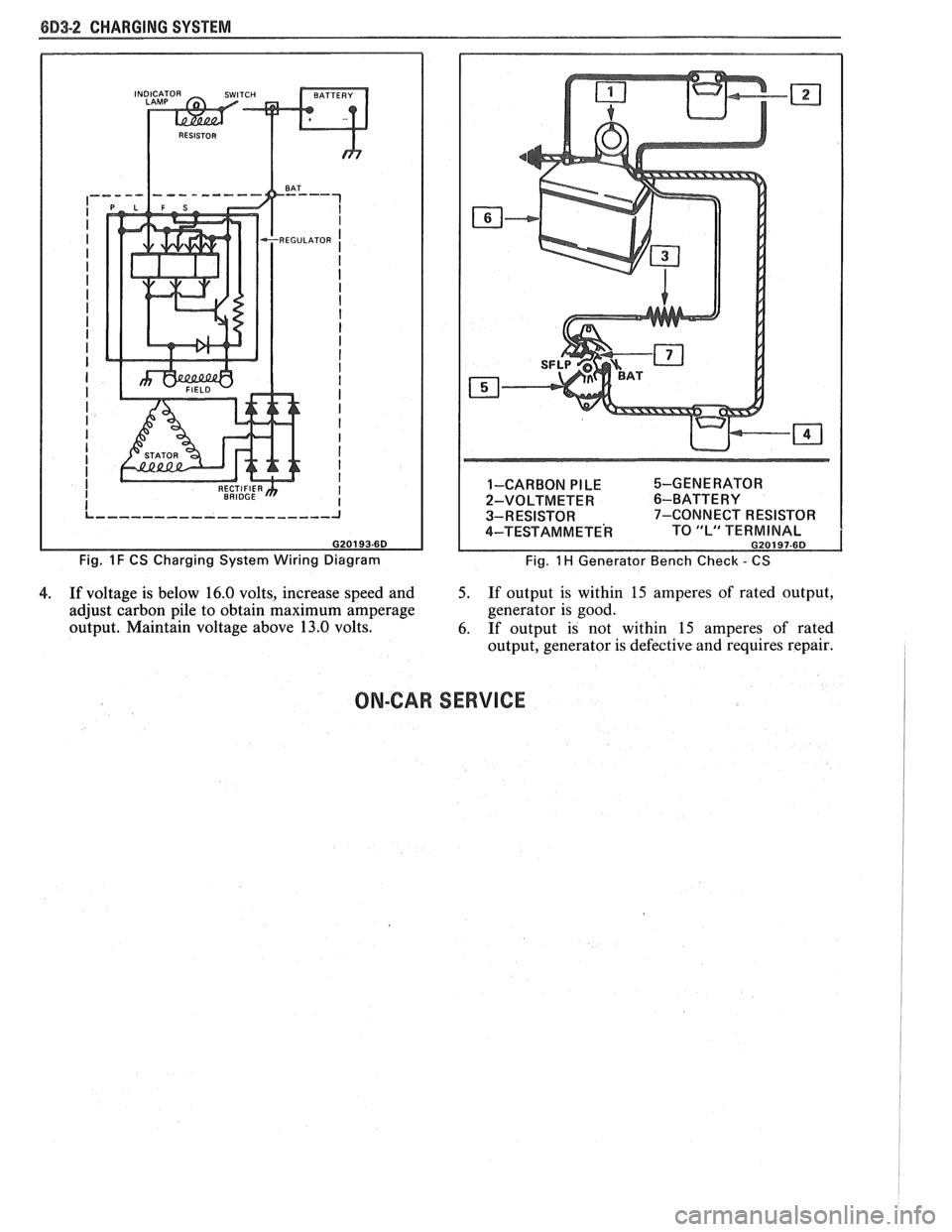
Fig. 1 F CS Charging System Wiring Diagram 1-CARBON
PILE %-GENERATOR
2-VOLTMETER
6-BATTERY
3-RESISTOR 7-CONNECT RESISTOR
4-TEST AM METE^ TO "L" TERMINAL G20197-6D
Fig. 1 H Generator Bench Check - CS
4. If voltage is below 16.0 volts, increase speed and 5. If output is within 15 amperes of rated output,
adjust carbon pile to obtain maximum amperage generator
is good.
output. Maintain voltage above 13.0 volts.
6. If output is not within
15 amperes of rated
output, generator is defective and requires repair.
ON-CAR SERVICE
Page 466 of 1825
CHARGING SYSTEM 6D3-3
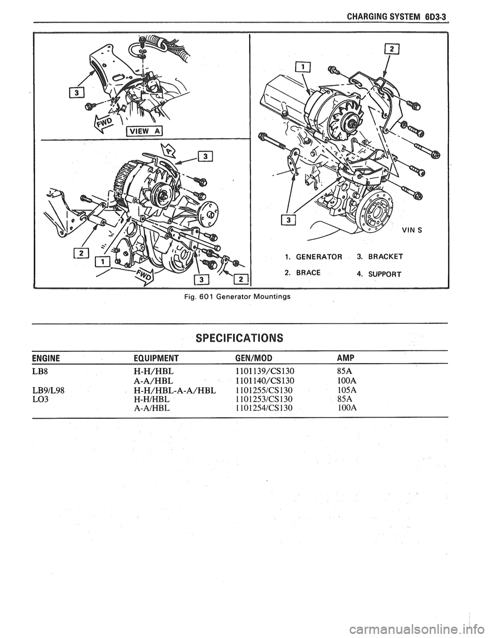
1. GENERATOR 3. BRACKET
4. SUPPORT
Fig.
60 1 Generator Mountings
SPECIFICATIONS
ENGINE EQUIPMENT GEN/MOD AMP
LB8 H-H/HBL 1101 139/CS130 85A
A-A/HBL 1101 140/CS130 1 OOA
LB9lL98 H-H/HBL-A-A/HBL 1 101 255lCS 130 105A
LO3 H-HIHBL 1101253lCS130 85A
A-AIHBL 1101254lCS130 1 OOA
Page 467 of 1825
6D3-4 CHARGING SYSTEM
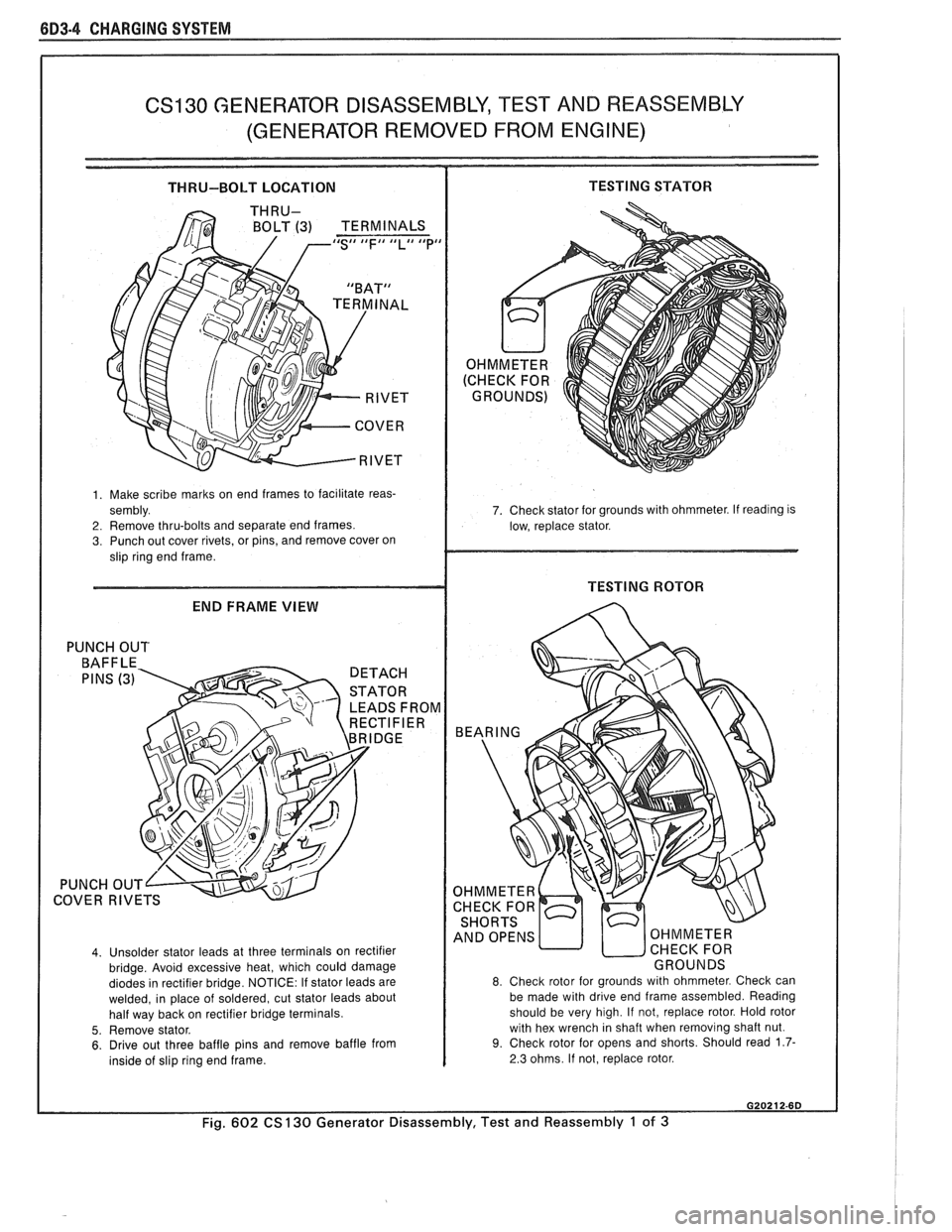
CS130 GENERATOR DISASSEMBLY, TEST AND REASSEMBLY
(GENERATOR REMOVED FROM ENGINE)
THRU-BOLT LOCATION TESTING STATOR
BOLT (3) TERMINALS IdS## tdFI# llLll Idpd
1. Make scribe marks on end frames to facilitate reas-
sembly.
2. Remove thru-bolts and separate end frames. 3. Punch out cover rivets, or pins, and remove cover on
slip ring end frame.
END FRAME VIEW
PUNCH OUT
LEADS FROM
COVER
RIVE
4. Unsolder stator leads at three terminals on rectifier
bridge. Avoid excessive heat, which could damage
diodes in rectifier bridge. NOTICE: If stator leads are
welded, in place of soldered, cut stator leads about
half way back on rectifier bridge terminals.
5. Remove stator. 6. Drive out three baffle pins and remove baffle from
inside of slip ring end frame. 7. Check stator
for grounds with ohmmeter. If
readlng IS
low, replace stator.
8. Check rotor for grounds with ohmmeter. Check can
be made with drive end frame assembled. Reading
should be very high. If not, replace rotor. Hold rotor
with hex wrench in shaft when removing shaft nut.
9. Check rotor for opens and shorts. Should read 1.7-
2.3 ohms. If not, replace rotor.
Fig. 602 CS 130 Generator Disassembly, Test and Reassembly 1 of 3
Page 468 of 1825
CHARGING SYSTEM 6D3-5
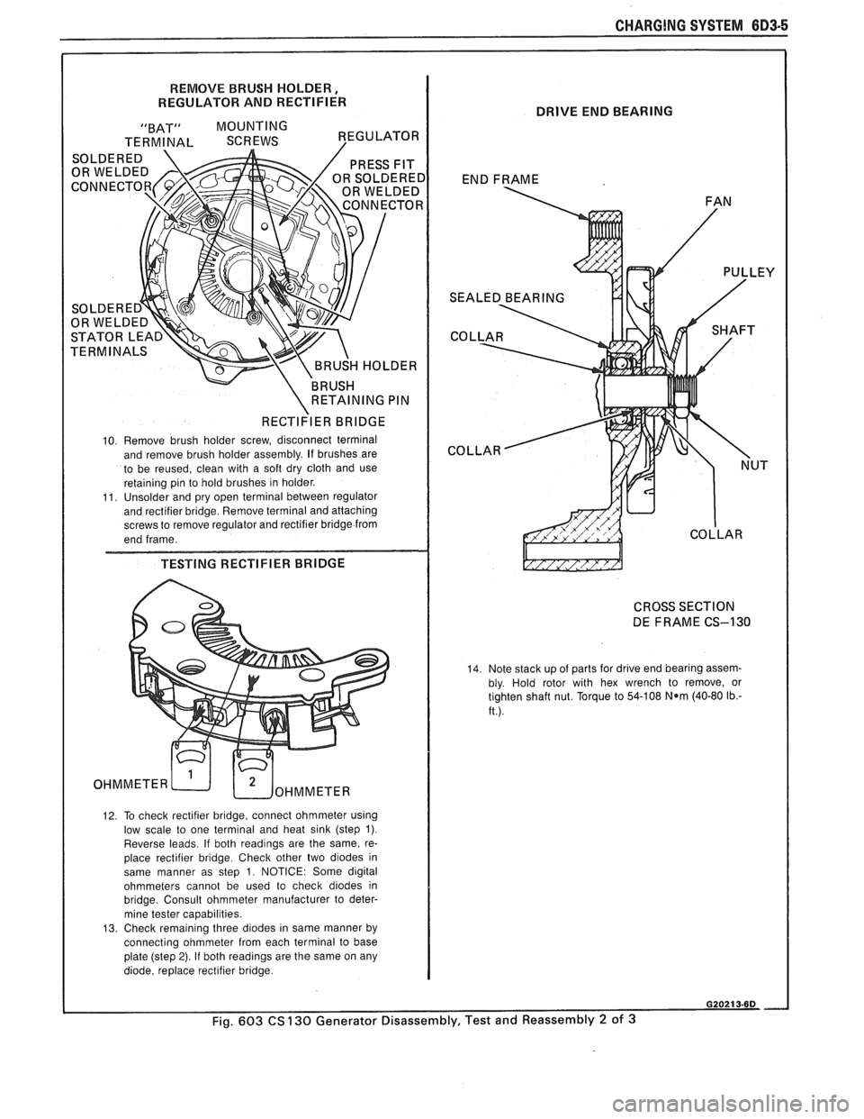
REMOVE BRUSH HOLDER,
REGULATOR AND RECTIFIER
"BAT" MOUNTING
TERMINAL SCREWS VEGULATOR I
RECTI~IER BRIDGE I
10. Remove brush holder screw, disconnect terminal
and remove brush holder assembly. If brushes are
to be reused, clean with a soft dry cloth and use
reta~nlng pin to hold brushes In holder
11 Unsolder and pry open termlnal between regulator
and
rectif~er br~dge Remove termlnal and attaching screws to remove regulator and rect~fier br~dge from
end frame
TESTING RECTIFIER BRIDGE
OHMMETER WoHMMETER
12. To check rectifier bridge, connect ohmmeter using
low scale to one terminal and heat sink (step 1).
Reverse leads. If both readings are the same, re-
place rectifier bridge. Check other two diodes in
same manner as step
1. NOTICE: Some digital
ohmmeters cannot be used to check diodes in
bridge. Consult ohmmeter manufacturer to deter-
mine tester capabilities.
13. Check remaining three diodes in same manner by
connecting ohmmeter from each terminal to base
plate (step
2). If both readings are the same on any
diode, replace rectifier bridge.
DRIVE END BEARING
END FRAME
FAN
CROSS SECTION
DE FRAME CS-130
14. Note stack up of parts for drive end bearing assem-
bly. Hold rotor with hex wrench to remove, or
tighten shaft nut. Torque to 54-108
N*m (40-80 Ib.-
ft.).
Fig. 603 CS 130 Generator Disassembly, Test and Reassembly 2 of 3
A
Page 469 of 1825
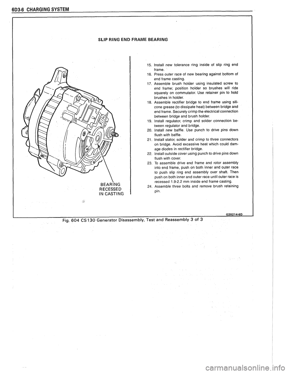
SLIP RING END FRAME BEARING
BEAR~NG RECESSED
IN CASTING
15. lnstall new tolerance ring inside of slip ring end
frame.
16. Press outer race of new bearing against bottom of
end frame casting.
17. Assemble brush holder using insulated screw to
end frame; position holder so brushes will ride
squarely on commutator. Use retainer pin to hold
brushes in holder.
18. Assemble rectifier bridge to end frame using sili-
cone grease (to dissipate heat) between bridge and
end frame. Securely crimp the electrical connection
between bridge and brush holder.
19. Install regulator, crimp and solder connection be-
tween regulator and bridge.
20. lnstall new baffle. Use punch to drive pins down
flush with baffle.
21. Install stator, solder and crimp to three connectors
on bridge. Avoid excessive heat which could dam-
age
d~odes In rect~f~er br~dge 22 Install outsrde cover uslng punch to drlve plns down
flush w~th cover
23 To assemble drlve end frame and rotor assembly tnto end frame, push on both Inner and outer race
to push
slrp rlng end assembly over shaft Then
push on both
Inner and outer race untll outer race IS recessed 1 9-2 2 mm lns~de end frame castrng 24 Assemble three bolts and remove brush retalnlng pin.
020214-6D
Fig. 604 CS 130 Generator Disassembly, Test and Reassembly 3 of 3
Page 470 of 1825
IGNITION SYSTEM 6D4-1
ON SYSTEM
CONTENTS
General Description ............................... 6D4-1 Service Procedures ............................. 6D4-3
Ignition System .......................................... 6D4-1
Ignition System .......................................... 6D4-3
Distributor Ignition ................................ 6D4-1
Distributor Ignition ................................ 6D4 -3
Diannosis .................................................... 6D4-3 On-Car Service ......................................... 6D4-5 -
Ignition System .......................................... (334-3 Ignition System ........................... .. .............. 6D4-5
Distributor ................................................. 6D4 -7 HE1 Distributor .................................... 6D4-3
GENERAL DESCRIPION
The engine electrical system includes the battery,
ignition (primary and secondary), starter (and related
wiring) and the generator (and related wiring).
Diagnostic charts (see Section 6D) will aid in
trouble-shooting system faults. When a fault is traced
to a particular component, refer to that components'
section of the service manual.
IGNITION SYSTEM
Distributor Ignition
The ignition circuit consists of the battery,
distributor, ignition switch, spark plugs and primary
and secondary wiring. Refer to the Battery portion of
this section for battery information.
PIE1 Distributor
The Nigh Energy Ignition (HEI) distributor with
Electronic Spark Timing (EST), used on most engines,
combines all ignition components in one unit. The
ignition coil is in the distributor cap and connects
through a resistance brush to the rotor.
The distributor has an internal magnetic pick-up
assembly which contains a permanent magnet, a pole
piece with internal teeth and a pick-up coil. When the
teeth of the timer core, rotating inside the pole piece,
line up with the teeth of the pole piece, an induced
voltage in the pick-up coil signals the electronic module
to trigger the coil primary circuit. The primary current
decreases and a high voltage is induced in the ignition
coil secondary winding. This voltage is directed
through the rotor and secondary leads to fire the spark
plugs. The capacitor in the distributor is for radio noise
suppression,
All spark timing changes in the
HE1 (EST)
distributor are done electronically by an Electronic
Control Module (ECM), which monitors information
from various engine sensors, computes the desired
spark timing and signals the distributor to change the
timing accordingly.
A back-up spark advance system
is incorporated to signal the ignition module in case of
(ECM) failure. No vacuum or mechanical advance is
used. Further (EST) information is found in sections 6E
Emissions Control, and
8A Electrical
Troubleshooting.
Ignition Timing
Timing specifications for each engine are listed in
Section
6E. When using a timing light, connect an
adapter between the No. 1 spark plug and the No. 1
spark plug wire, or use an inductive type pick-up.
Do
not pierce the plug lead.
Once the insulation of the
spark plug cable has been broken, voltage will jump to
the nearest ground, and the spark plug will not fire
properly.
Always follow the tune-up label
procedures when adjusting timing.
Some engines will incorporate a magnetic timing
probe hole for use with special electronic timing
equipment. Fig.
1A shows a typical magnetic probe
hole. Consult manufacturer's instructions for use of
this equipment.
Secondary Wiring
The spark plug wiring used with ignition systems
is a carbon impregnated cord conductor, encased in an
8MM (5/16") diameter silicone rubber jacket. The
silicone jacket withstands very high temperatures and
also provides an excellent insulator for the higher
voltage of the
HE1 system. Silicone spark plug boots
form a tight seal on the plug.
The boot should be
twisted 1/2 turn before removing. Care should
also be exercised when connecting a timing light or
other pick-up equipment. Do not force anything
between the boot and wiring, or through the silicone
jacket. Connections should be made in parallel using
an adapter. DO NOT pull on the wire to remove. Pull
on the boot, or use a tool designed for this purpose.
Spark Plugs
Resistor type, tapered seat spark plugs are used
on all engines (except aluminum heads). No gasket is
used on these tapered seat plugs. See Figs.
1B and 1C
for an explanation of coding on spark plugs.
Normal service is assumed to be a mixture of
idling, slow speed, and high speed driving. Occasional
or intermittent high-speed driving is needed for good