PONTIAC FIERO 1988 Service Repair Manual
Manufacturer: PONTIAC, Model Year: 1988, Model line: FIERO, Model: PONTIAC FIERO 1988Pages: 1825, PDF Size: 99.44 MB
Page 471 of 1825
604-2 IGNITION SYSTEM
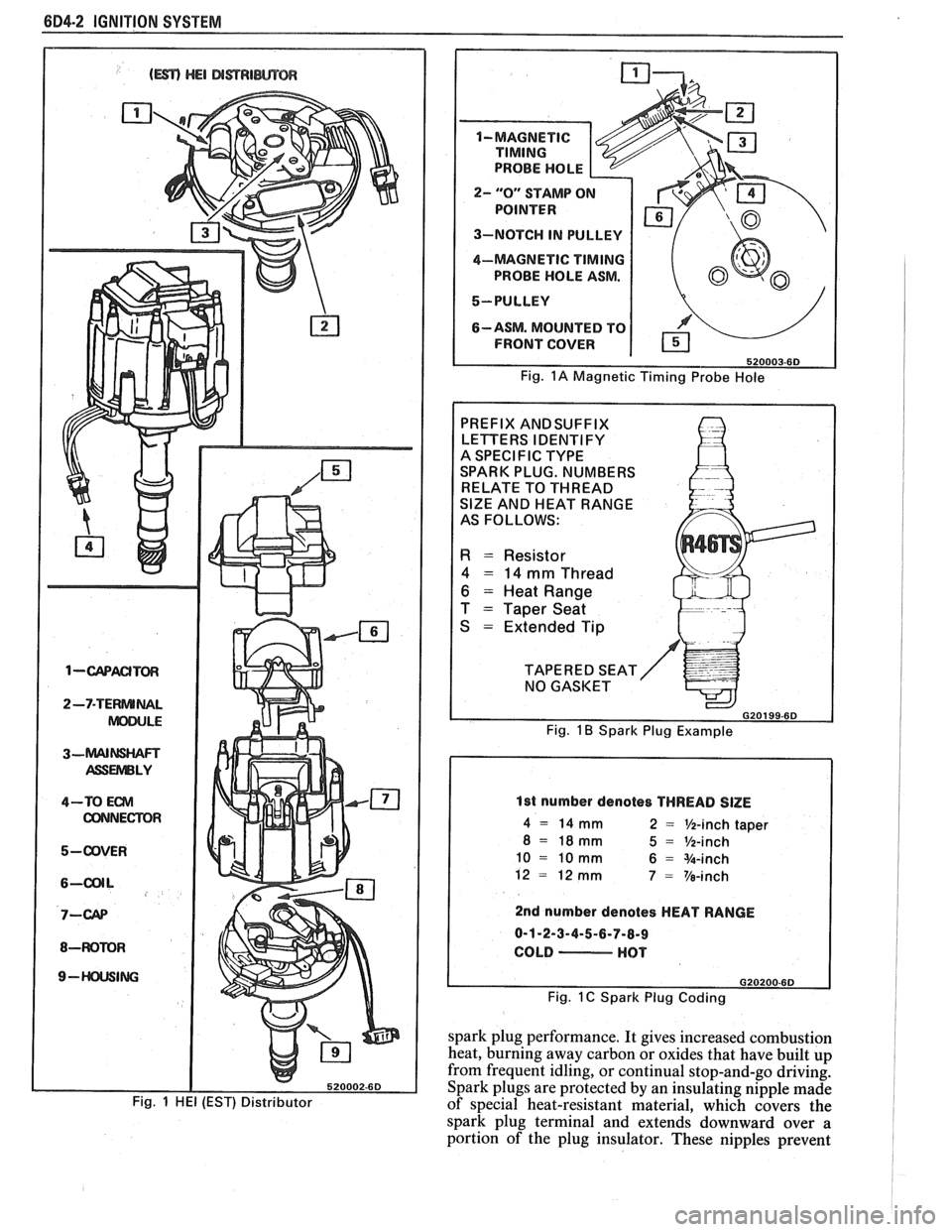
1-wACITm
2-7-TERNUNAL
ASSUVlBLY
4-TO Em
CONNECTOR
5-ODVER
8-WOMR
9- ING
Fig. 1 HE1 (EST) Distributor
2- "0" STAMP O
3-NOTCH IN PULLEY
4-MAGNETIC
TIMING
PROBE HOLE ASM.
5-PULLEY
6-ASM. MOUNTED TO
FRONT COVER
Fig. 1A Magnetic Timing Probe Hole
PREFIX ANDSUFFIX
LETTERS IDENTIFY
A SPECIFIC TYPE
SPARK PLUG. NUMBERS
RELATE TO THREAD
SlZE AND HEAT RANGE
AS FOLLOWS:
R = Resistor
4 = 14 mm Thread
6 = Heat Range
T
= Taper Seat
S
= Extended Tip
TAPERED SEAT NO GASKET
G20199-6D
Fig. 1 B Spark Plug Example
1st number denotes THREAD SlZE
4 = 14 mm 2 = %-inch taper
8 = 18mm 5 = %-inch
10 = 10 mm 6 = %-inch
12
= 12 mm 7 = Ve-inch
2nd number denotes HEAT RANGE
0-1-2-3-4-5-6-7-8-9
COLD
- HOT
Fig. 1 C Spark Plug Coding
spark plug performance. It gives increased combustion
heat, burning away carbon or oxides that have built up
from frequent idling, or continual stop-and-go driving.
Spark plugs are protected by an insulating nipple made
of special heat-resistant material, which covers the
spark plug terminal and extends downward over
a
portion of the plug insulator. These nipples prevent
Page 472 of 1825
IGNITION SYSTEM 6B4-3
flash-over, which causes engine misfiring. Do not
mistake corona discharge for flash-over, or a shorted
insulator. Corona is a steady blue light appearing
around the insulator, just above the shell crimp. It is
the visible evidence of a high-tension field and has no
effect on ignition performance. Usually it can be
detected only in darkness. This discharge may repel
dust particles, leaving a clear ring on the insulator just
above the shell. This ring is sometimes mistakenly
regarded as evidence that combustion gases have blown
out between shell and insulator.
lgnition Switch
The mechanical switch is located in the steering
column on the right hand side just below the steering
wheel. The electrical switching portion of the assembly
is separate from the key and lock cylinder. However,
both are synchronized and work in conjunction with
each other through the action of the actuator rod
assembly.
For a complete explanation of the key and lock
cylinder, and the actuator rod assembly, see
STEERING, Section
38. See Section 8 for electrical
switching.
DIAGNOSIS
IGNITION SYSTEM
Spark Plugs
Worn or dirty plugs may give satisfactory
operation at idling speed, but at higher RPM they
frequently fail. Faulty plugs are indicated in a number
of ways: poor fuel economy, power loss, loss of speed,
hard starting and generally poor engine performance.
Spark plugs may also fail due to carbon fouling,
excessive gap, or a broken insulator. Fouled plugs may
be indicated by black carbon
deposits. The black deposits are usually the result of
slow-speed driving and short runs, where sufficient
engine operating temperature is seldom reached. Worn
pistons, rings, faulty ignition, over-rich carburetion
and spark plugs which are too cold will also result in
carbon deposits.
Excessive gap wear, on plugs of low mileage,
usually indicates the engine is operating at high speeds,
or loads that are consistently greater than normal, or
that a plug which is too hot is being used. Electrode
wear may also be the result of plug overheating,
causcd
by combustion gases leaking past the threads due to
insufficient torquing of the spark plug. Excessively lean
carburetion will also result in accelerated electrode
wear.
Broken insulators are usually the result of
improper installation, or carelessness when regapping
the plug. Broken upper insulators usually result from
a poor fitting wrench, or an outside blow. The cracked
insulator may not show up right away, but will as soon
as oil or moisture penetrates the crack. The crack is
usually just below the crimped part of shell and may
not be visible.
Broken lower insulators usually result from
carelessness when regapping and generally are visible.
This type of break may result from the plug operating
too "hot", which may happen in periods of high-speed
operation or under heavy loads. When regapping a
spark plug, always make the gap adjustment by
bending the ground (side) electrode. Spark plugs with
broken insulators should always be replaced.
HE1 Distributor
See Unit Repair for distributor disassembly, test
and reassembly of individual distributor components,
when the distributor is removed from the vehicle. See
On-Car Service for distributor removal and installation
and for component removal with distributor in car. See
Section 6E for
HE1 and EST diagnosis.
SERVICE PROCEDURES
IGNITION SYSTEM
Distributor Ignition
NOTICE: This procedure is generally true for
most carlines. Where procedure is different, or
where additional information is required, see
"ON-CAR SERVICE" for specific
carline.
HE1 DISTRIBUTOR
Service Precautions
1. When making compression checks, disconnect
the ignition switch feed wire at the distributor.
When disconnecting this connector,
do not use
a screwdriver or tool to release the locking tab, as
it may break.
2. No periodic lubrication is required. Engine oil
lubricates the lower bushing and an oil-filled
reservoir provides lubrication for the upper
bushing. 3.
The tachometer (TACH) terminal is next to the
ignition switch (BAT) connector on the
distributor cap.
NOTICE: The tachometer terminal must
NEVER be allowed to touch ground, as damage
to the module and/or ignition coil can result.
Some tachometers currently in use may NOT be
compatible with the High Energy Ignition System.
Consult the manufacturer of the tachometer if
questions arise.
4. Dwell adjustment is controlled by the module,
and cannot be adjusted.
5. The material used to construct the spark plug
cables is very soft. This cable will withstand more
heat and carry a higher voltage, but scuffing and
cutting become easier. The spark plug cables
must be routed correctly to prevent
chafing or
cutting. See Spark Plug Section. When removing
Page 473 of 1825
684.4 IGNITION SYSTEM
a spark plug wire from a spark plug, twist the 4. Do not wipe grease from module, or distributor
boot on the spark plug and pull
on the boot to base,
if same module is to be replaced.
remove the wire, or use a special tool designed to
remove spark plug boots.
Install or Connect
Remove or Disconnect
1. Ignition switch battery feed wire and tachometer
lead (if equipped) from distributor cap. Also
release the coil connectors from the cap. (DO
NOT use a screwdriver or tool to release the
locking tabs.)
2. Distributor cap by turning four screws
counterclockwise. Move cap out of the way.
3. Four-terminal ECM harness from distributor.
4. If necessary, remove secondary wires from cap,
release wiring harness latches and remove wiring
harness retainer. The spark plug wire numbers
are indicated on the retainer.
5. Distributor clamp screw and hold-down clamp.
6. Note position of rotor, then pull distributor up
until rotor just stops turning counterclockwise
and again note position of rotor.
To insure correct timing of the distributor,
the distributor must be INSTALLED with
the rotor correctly positioned as noted.
If the engine was accidentally cranked after the
distributor was removed, the following procedure can
be used for installing:
1. Remove No. 1 spark plug.
2. Place finger over No. 1 spark plug hole and crank
engine slowly until compression is felt.
3. Align timing mark on pulley to "0" on engine
timing indicator.
4. Turn rotor to point between No. 1 and No. 8
spark plug towers on distributor cap on V8
engines, between No. 1 and No. 6 on V6 engines,
and No.
1 and No. 4 on 4 cylinder engines.
5. Install distributor and connect ignition feed wire.
6. Install distributor cap and spark plug wires.
7. Check engine timing (see Set Ignition Timing).
Install or Connect
1. Insert distributor, positioning rotor as removed.
2. Distributor hold-down clamp and screw.
3. Wiring harness retainer and secondary wires, if
removed.
4. ECM harness connector.
5. Distributor cap.
6. Coil connectors.
7. Battery wire and tachometer lead, if equipped.
Module
It is not necessary to remove the distributor from
car.
Remove or Disconnect
1. Distributor cap and rotor.
2. Two module attaching screws, and lift module
UP. 3. Leads from module. (Observe color code on leads
as these cannot be interchanged.)
NOTICE: If a new module is to be installed, a
package of silicone grease will be included with it.
Spread the grease on the metal face of the module
and on the distributor base where the module
seats. This grease is necessary for module cooling.
1. Module.
2. Module leads (observe color code).
3. Attaching screws to module.
4. Rotor.
5. Cap.
Pick-Up Coil
1. Remove distributor from car and follow
instructions in Unit Repair, as applicable.
Rotor
Fig. 1
1. Remove distributor cap.
2. The rotor is retained by two screws and is
provided with a slot which fits over a square lug,
,
so that the rotor can be installed in only one
position.
Integral Ignition Coil
Fig. I
Remove or Disconnect
1. Distributor cap.
2. Three coil cover attaching screws, and lift off
cover.
3. Coil attaching screws and lift ignition coil and
leads from cap.
Install or Connect I
1. Coil and attaching screws.
2. Coil leads.
3. Coil cover and attaching screws.
Capacitor
Fig. 1
The capacitor is part of the coil wire harness
assembly. Since the capacitor is used only for radio
noise suppression, it will seldom need replacement.
Remove or Disconnect I
1. Distributor cap and rotor.
2. Capacitor attaching screw and unplug connector
from module. It may help to loosen the module.
Install or Connect I
1. Plug into module.
2. Capacitor and hold-down screw (be sure ground
lead is under screw).
Page 474 of 1825
IGNITION SYSTEM 6014.5
3. Rotor and cap. 4. Turn off the engine and remove the timing light.
Reconnect the number one spark plug wire, if
Set Ignition Timing removed.
Spark Plug Wires 1. Refer to the tune-up label located in the engine
compartment. Follow all instructions on the Use
care when removing spark plug wire boots
label. from
spark plugs. Twist the boot
1/2 turn before
removing and pull on the
boot only to remove the
With ignition off, connect the pick-up lead of
timing light to the number one spark plug. Use
a jumper lead between the wire and plug, or an
inductive type pick-up.
DO NOT pierce the wire,
or attempt to insert a wire between the boot and
the wire. Connect the timing light power leads
according to manufacturer's instructions.
Start the engine and aim the timing light at the
timing mark. The line on the balancer or pulley
will line up at the timing mark. If a change is
necessary, loosen the distributor hold-down
clamp bolt at the base of the distributor. While
observing the mark with the timing light, slighty
rotate the distributor until the line indicates the
correct timing. Tighten the hold-down bolt and
re-check the timing. wire.
When replacing plug wires, route the wires
correctly and through the proper retainers. Failure to
route the wires properly can lead to radio ignition noise
and crossfiring of the plugs, or shorting of the leads to
ground.
Special care should be exercised when reinstalling
spark plug boots, to assure that the metal terminal
within the boot is fully seated on the spark plug
terminal and that the boot has not moved on the wire.
If boot to wire movement has occurred, the boot will
give a false visual impression of being fully seated.
A
good check to assure that boots have been properly
assembled is to push sideways on the installed boots.
If they have been correctly installed, a stiff boot, with
only slight looseness, will be noted. If the terminal has
not been properly seated on the spark plug, only the
resistance of the rubber boot will be felt when pushing
sideways.
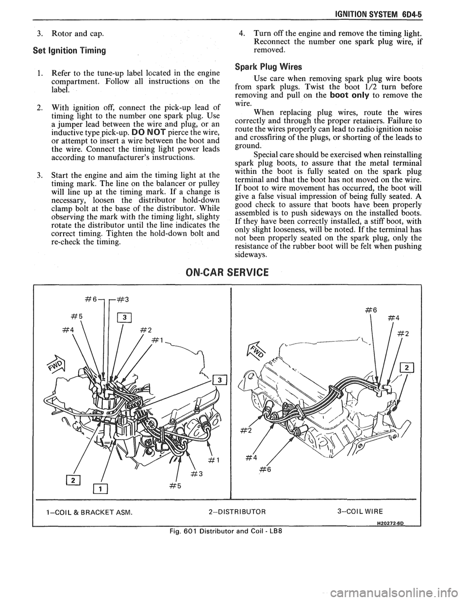
ON-CAR SERVICE
I I -COI L & BRACKET ASM. 2-DISTRIBUTOR 3-COIL WIRE I
Fig. 601 Distributor and Coil - LB8
Page 475 of 1825
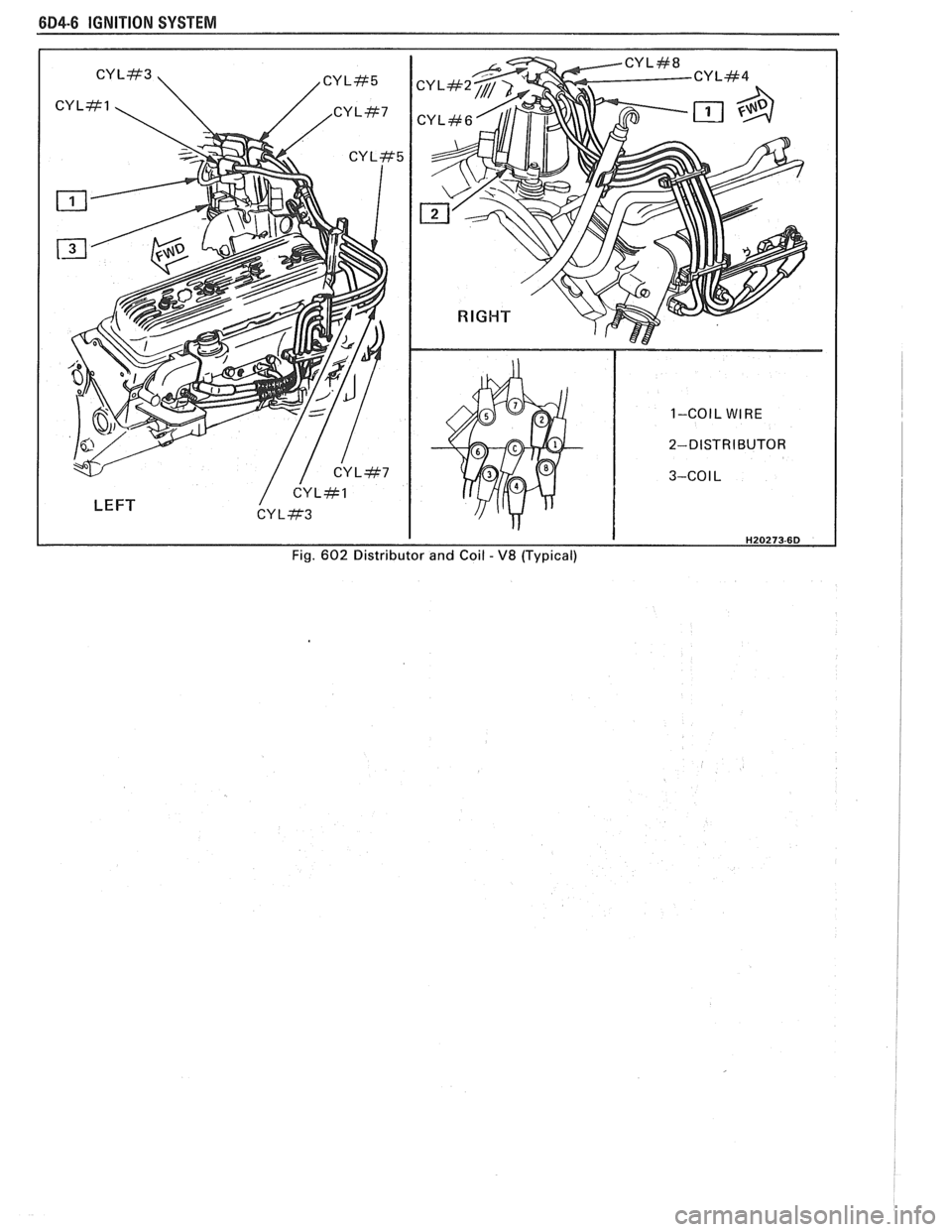
6D4-6 IGNITION SYSTEM
LEFT
1-COIL WIRE
2-DISTRIBUTOR
3-CO
I L
Fig.
602 Distributor and Coil - V8 (Typical)
Page 476 of 1825
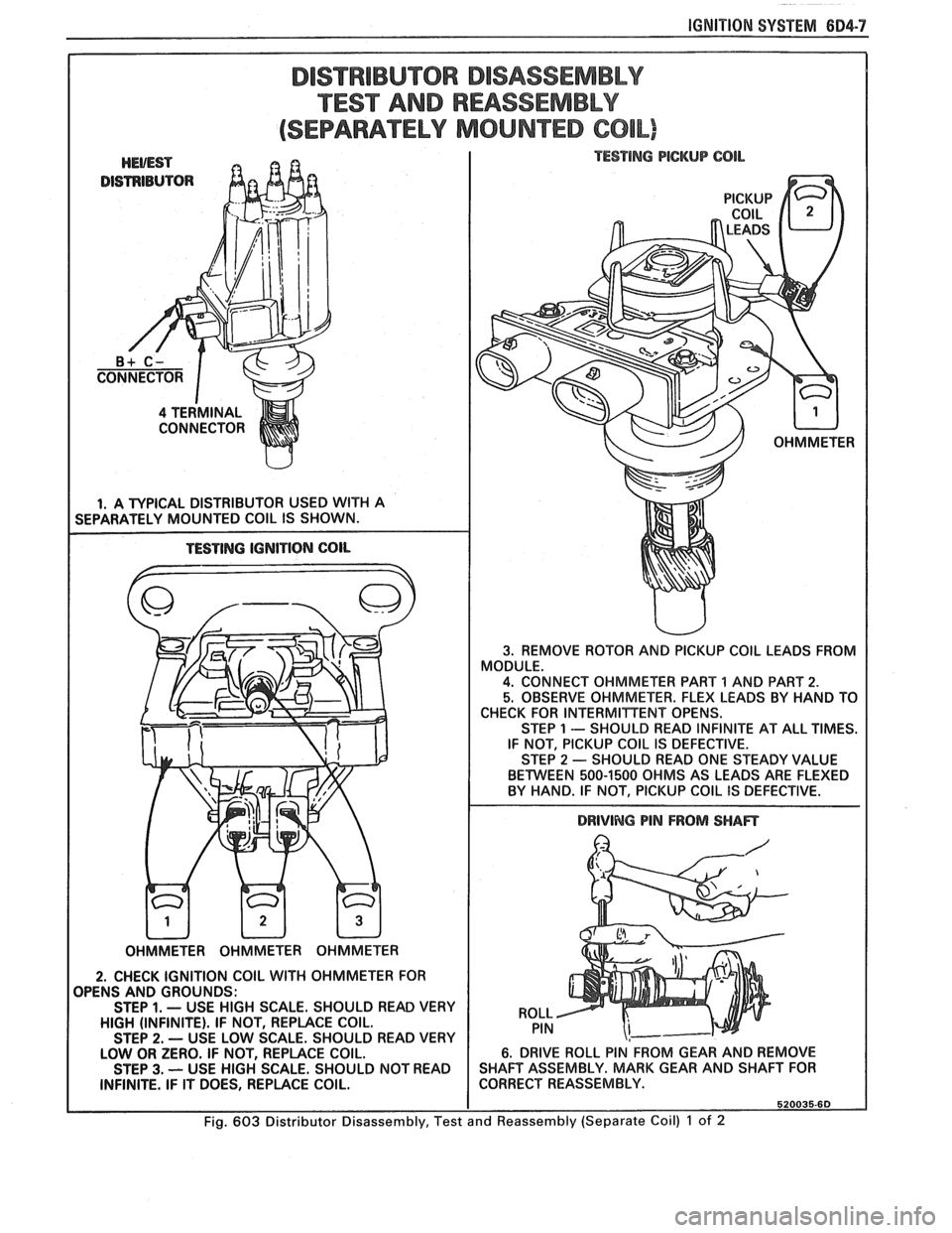
IGNITION SYSTEM 604-7
DISTRIBUTOR DISASSEMBLY
TEST AND REASSEMBLY
(SEPARATELY MOUNTED COIL)
DISTRIBUTOR
I 4 TERMINAL
CONNECTOR
I I. A TYPICAL DISTRIBUTOR USED WlTH A
SEPARATELY MOUNTED COlL IS SHOWN.
I TESTING PlCKUP CQlL
TESTING IGNITION COlL
I DRIVING PIN FROM SHAFT
I OHMMETER OHMMETER OHMMETER
2. CHECK IGNITION COIL WlTH OHMMETER FOR
OPENS AND GROUNDS:
STEP
1. - USE HIGH SCALE. SHOULD READ VERY
HIGH (INFINITE). IF NOT, REPLACE COIL.
STEP
2. - USE LOW SCALE. SHOULD READ VERY
LOW OR ZERO. IF NOT, REPLACE COIL.
STEP
3. -- USE HIGH SCALE. SHOULD NOT READ
INFINITE. IF IT DOES, REPLACE COIL.
Fig. 603 Distributor Disassembly, Test
w
3. REMOVE ROTOR AND PICKUP COlL LEADS FROM
MODULE.
4. CONNECT OHMMETER PART 1 AND PART 2.
5. OBSERVE OHMMETER. FLEX LEADS BY HAND TO
CHECK FOR INTERMITTENT OPENS.
STEP
1 - SHOULD READ INFINITE AT ALL TIMES.
IF NOT, PICKUP COlL IS DEFECTIVE.
STEP
2 - SHOULD READ ONE STEADY VALUE
BETWEEN 500-1500 OHMS AS LEADS ARE FLEXED
BY HAND. IF NOT, PICKUP COIL
IS DEFECTIVE.
ROLL PIN
6. DRIVE ROLL PIN FROM GEAR AND REMOVE
SHAFT ASSEMBLY. MARK GEAR AND SHAFT FOR
CORRECT REASSEMBLY.
520035.60
and Reassembly (Separate Coil) 1 of 2
Page 477 of 1825
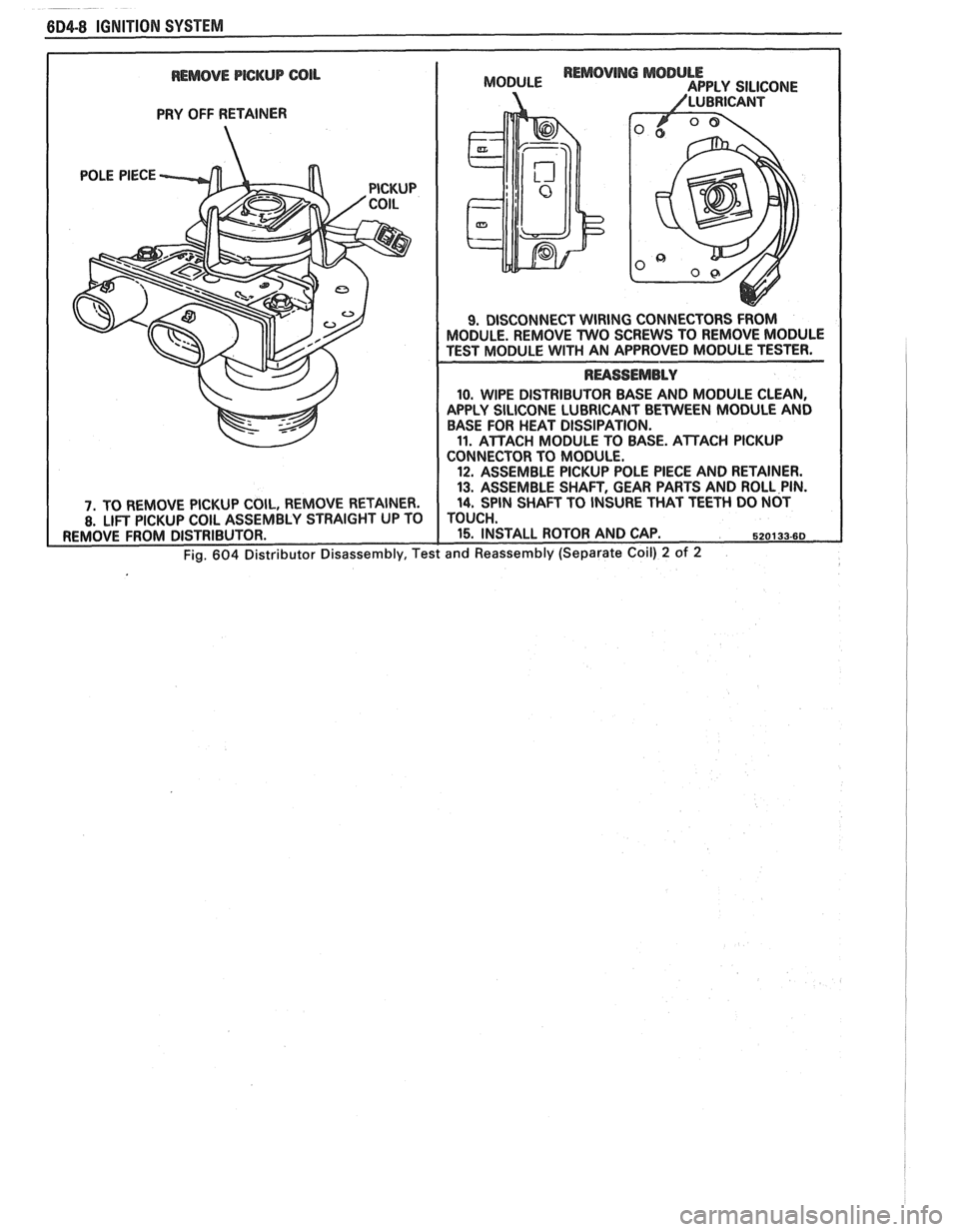
REMOVE PICKUP COIL
PRY OFF RETAINER
10. WIPE DISTRIBUTOR BASE AND MODULE CLEAN,
APPLY SILICONE LUBRICANT BETWEEN MODULE AND
BASE FOR HEAT DISSIPATION.
11. ATTACH MODULE TO BASE. ATTACH PICKUP
CONNECTOR TO MODULE.
12. ASSEMBLE PICKUP POLE PIECE AND RETAINER.
13. ASSEMBLE SHAFT, GEAR PARTS AND ROLL PIN.
Page 478 of 1825
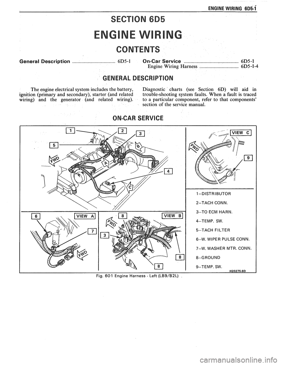
ENGINE WIRING 6~5-1x
SECTION 6B5
General Description ................................. 6D5-1 On-Car Service ........................................ 6D5 -1
Engine Wiring Harness ..................... .. .. 6D5 -1-4
GENERAL DESCRIPTION
The engine electrical system includes the battery, Diagnostic charts (see Section 6D) will aid in
ignition (primary and secondary), starter (and related trouble-shooting system faults. When
a fault is traced
wiring) and the generator (and related wiring). to a particular component, refer to that components'
section of the service manual.
ON-CAR SERVICE
Page 479 of 1825
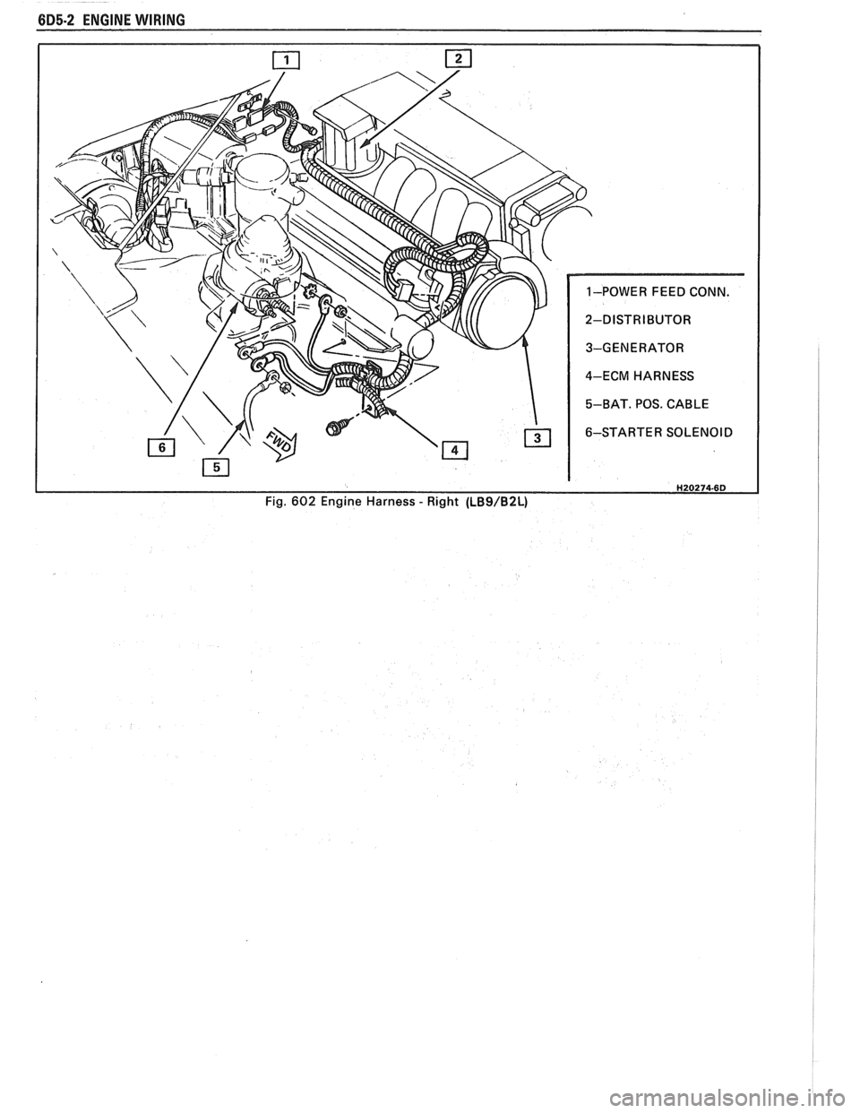
685-2 ENGINE WIRING
H20274-6D Fig. 602 Engine Harness - Right (LBS/B2L)
Page 480 of 1825
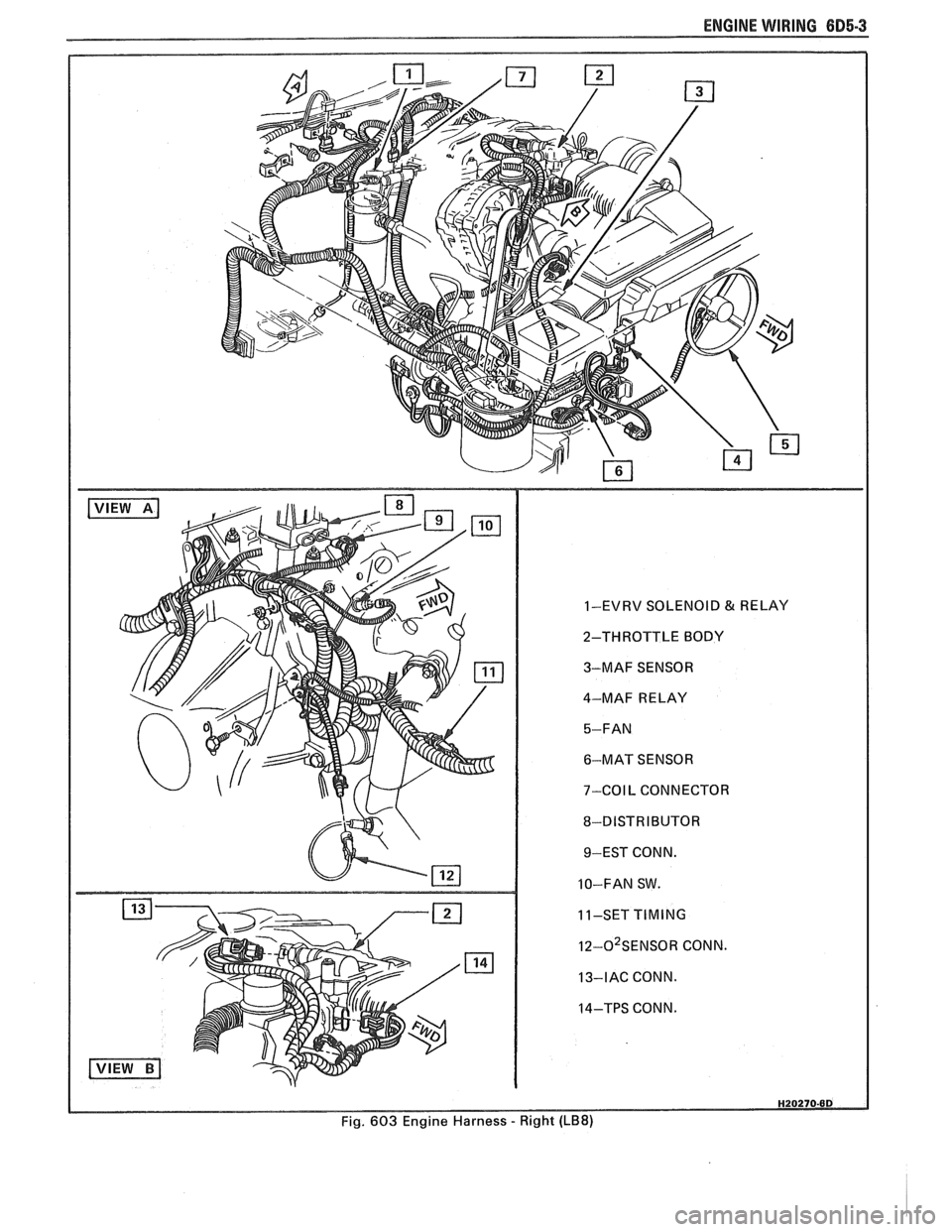
ENGINE WIRING 605.3
1-EVRV SOLENOID & RELAY
2-THROTTLE BODY
3-MAF SENSOR
4-MAF RELAY
6-MAT SENSOR
7-COIL CONNECTOR
8-DISTRIBUTOR 9-EST CONN.
10-FAN SW.
11-SET
TIMING
I~-O~SENSOR CONN.
13-IAC CONN.
14-TPS CONN.
Fig. 603 Engine Harness
- Right (LB8)