PONTIAC FIERO 1988 Service Repair Manual
Manufacturer: PONTIAC, Model Year: 1988, Model line: FIERO, Model: PONTIAC FIERO 1988Pages: 1825, PDF Size: 99.44 MB
Page 451 of 1825

Page 452 of 1825
CRANKING SYSTEM CD2-1
CRANK NG SYSTEM
General Description ................................. 6D2-1 Service Procedures .................................. 6D2-3
Cranking System ......................... ... ........ 6D2- 1 Cranking
System ..................... .. ............. 6D2-3
Starter Motor ............................................. 6D2-1 On-Car Service ....................................... 6D2-4 Solenoid .................................................. 6D2- 1
Starter ........................... ... ...................... 6D2-4 Diagnosis ..................................................... 6D2-1 Specifications ............................................. 6D2- I I Cranking System ......................... ... ...... 6D2- 1
Unit Repair ............................................ 6D2-6- 1 1
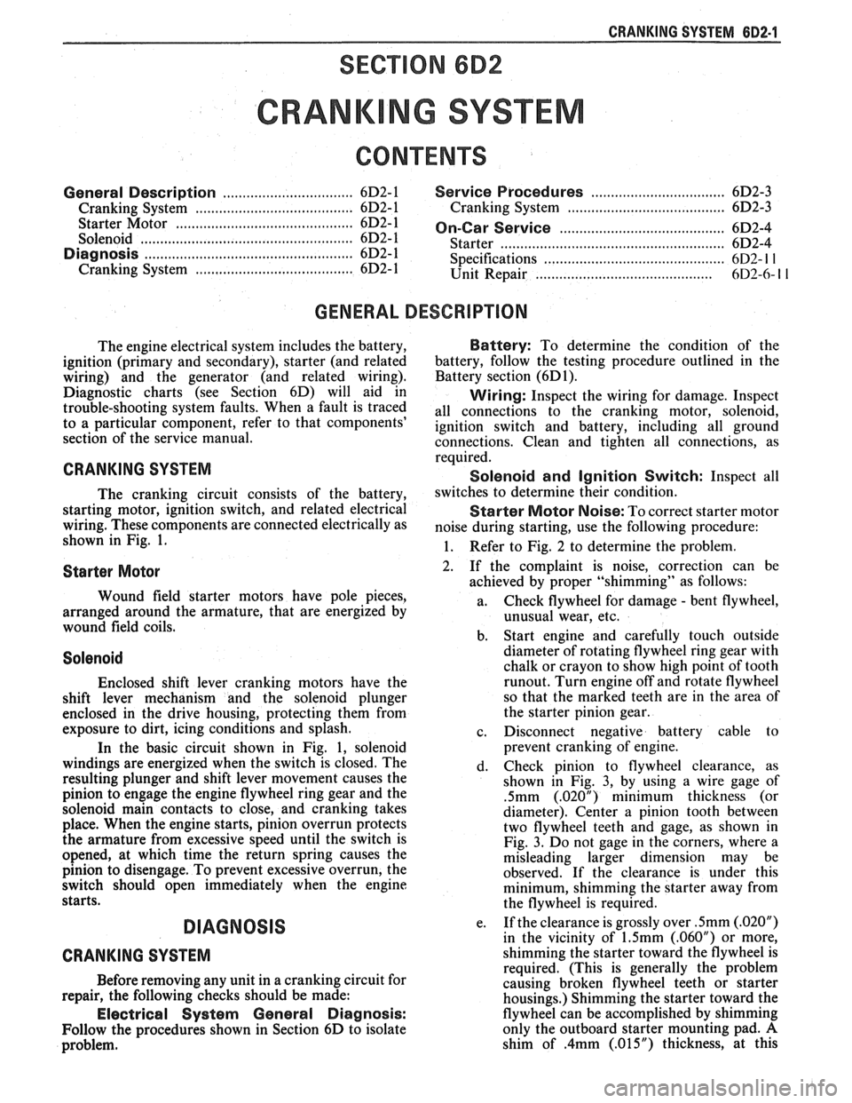
GENERAL DESCRIPTION
The engine electrical system includes the battery, Battery: To determine the condition of the
ignition (primary and secondary), starter (and related battery,
follow the testing procedure outlined in the
wiring) and the generator (and related wiring). Battery section
(6D1).
Diagnostic charts (see Section 6D) will aid in Wiring: Inspect the wiring for damage. Inspect trouble-shooting system faults. When a fault is traced all connections to the cranking motor, solenoid, to a articular component, refer to that components' ignition switch and battery, including all ground
section of the service manual.
connections. Clean and tighten all connections, as
CRANKING SYSTEM
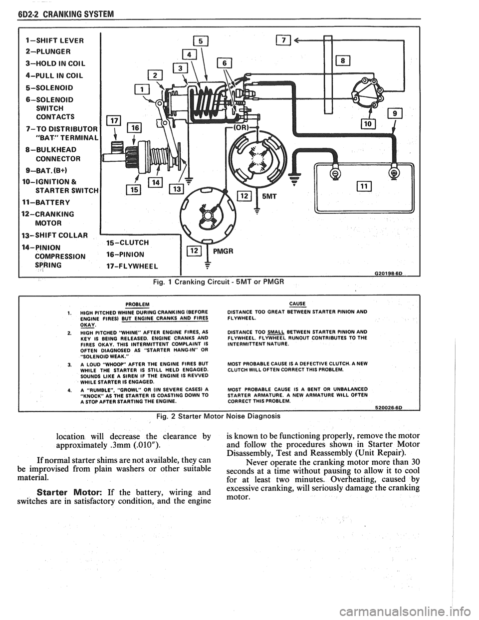
The cranking circuit consists of the battery,
starting motor, ignition switch, and related electrical
wiring. These components are connected electrically as
shown in Fig. 1.
Starter Motor
Wound field starter motors have pole pieces,
arranged around the armature, that are energized by
wound field coils.
Solenoid
Enclosed shift lever cranking motors have the
shift lever mechanism and the solenoid plunger
enclosed in the drive housing, protecting them from
exposure to dirt, icing conditions and splash.
In the basic circuit shown in Fig. 1, solenoid
windings are energized when the switch is closed. The
resulting plunger and shift lever movement causes the
pinion to engage the engine flywheel ring gear and the
solenoid main contacts to close, and cranking takes
place. When the engine starts, pinion overrun protects
the armature from excessive speed until the switch is
opened, at which time the return spring causes the
pinion to disengage. To prevent excessive overrun, the
switch should open immediately when the engine
starts.
DIAGNOSIS
CRANKING SYSTEM
Before removing any unit in a cranking circuit for
repair, the following checks should be made:
Electrical System General Diagnosis:
Follow the procedures shown in Section 6D to isolate
problem. required.
Solenoid
and Ignition Switch: Inspect all
switches to determine their condition.
Starter Motor Noise: To correct starter motor
noise during starting, use the following procedure:
1. Refer to Fig. 2 to determine the problem.
2. If the complaint is noise, correction can be
achieved by proper "shimming" as follows:
a. Check
flywheel for damage
- bent flywheel,
unusual wear, etc.
b. Start
engine and carefully touch outside
diameter of rotating flywheel ring gear with
chalk or crayon to show high point of tooth
runout. Turn engine off and rotate flywheel
so that the marked teeth are in the area of
the starter pinion gear.
c. Disconnect negative battery cable to
prevent cranking of engine.
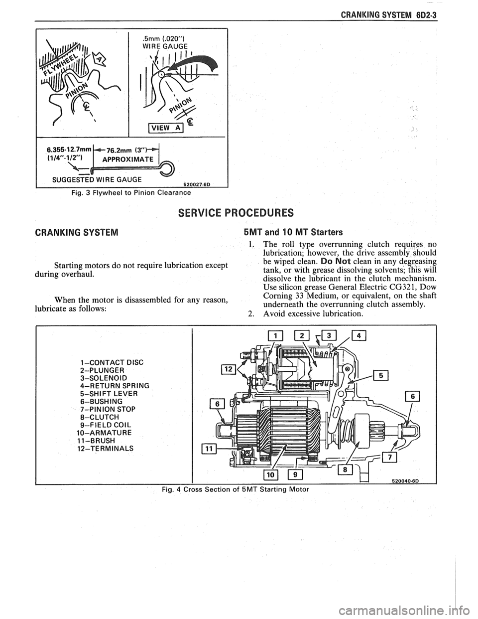
d. Check pinion to flywheel clearance, as
shown in Fig. 3, by using a wire gage of
.5mm (.02OU) minimum thickness (or
diameter). Center a pinion tooth between
two flywheel teeth and gage, as shown in
Fig. 3. Do not gage in the corners, where a
misleading larger dimension may be
observed. If the clearance is under this
minimum, shimming the starter away from
the flywheel is required.
e. If
the clearance is grossly over
.5mm (.02OU)
in the vicinity of 1.5mm (.06OU) or more,
shimming the starter toward the flywheel is
required. (This is generally the problem
causing broken flywheel teeth or starter
housings.) Shimming the starter toward the
flywheel can be accomplished by shimming
only the outboard starter mounting pad.
A
shim of .4mm (.015") thickness, at this
Page 453 of 1825
6D2-2 CRANKING SYSTEM
1-SWIFT LEVER m
SPRING 17-FLYWHEEL I
I G20198-6D
Fig. 1 Cranking Circuit - 5MT or PMGR
PROBLEM CAUSE - 1. HIGH PITCHED WHINE DURING CRANKING (BEFORE DISTANCE
TOO GREAT BETWEEN STARTER PINION AND
ENGINE FIRES) BUT ENGINE CRANKS AND FIRES FLYWHEEL.
OKAY - 2. HlGH PITCHED "WHINE"
AFTER ENGINE FIRES, AS
KEY IS BEING RELEASED. ENGINE CRANKS AND
FIRES OKAY. THlS INTERMITTENT COMPLAINT IS
OFTEN DIAGNOSED AS "STARTER HANG-IN"
OR "SOLENOID WEAK."
3. A LOUD "WHOOP" AFTER THE ENGINE FIRES BUT
WHILE THE STARTER IS STILL HELD ENGAGED.
SOUNDS
LIKE A SIREN IF THE ENGINE IS REVVED
WHILE STARTER IS ENGAGED.
4. A "RUMBLE. "GROWL" OR (IN SEVERE CASES) A
"KNOCK" AS THE STARTER IS COASTING DOWN TO
A STOP AFTER STARTING THE ENGINE. DISTANCE
TOO
SMALL BETWEEN STARTER PINION AND
FLYWHEEL. FLYWHEEL RUNOUT CONTRIBUTES TO THE
INTERMITTENT NATURE.
MOST PROBABLE CAUSE IS A DEFECTIVE CLUTCH. A NEW
CLUTCH
WlLL OFTEN CORRECT THlS PROBLEM.
MOST PROBABLE CAUSE IS A BENT OR UNBALANCED
STARTER ARMATURE. A NEW ARMATURE
WlLL OFTEN
CORRECT THlS PROBLEM.
620026.60
Fig. 2 Starter Motor Noise Diagnosis
location will decrease the clearance by is known to be functioning properly, remove the motor
approximately
.3mm (.01OU). and follow the procedures shown in Starter Motor
Disassembly, Test and Reassembly (Unit Repair).
If normal starter shims are not available, they can
Never operate the cranking motor more than 30
be improvised from plain washers or other suitable
seconds at a time without pausing to allow it to cool material.
for at least two minutes. Overheating, caused by
excessive cranking, will seriously
damage the cranking Starter Motor: If the battery, wiring and motor, switches are in satisfactory condition, and the engine
Page 454 of 1825
CRANKING SYSTEM 882-3
.5mm (.02OU)
WIRE GAUGE
I
Fig. 3 Flywheel to Pinion Clearance
SERVICE PROCEDURES
CRANKING SYSTEM 5MT and 10 MT Starters
1. The roll type overrunning clutch requires no
lubrication; however, the drive assembly should
Starting motors do not require lubrication except be wiped clean.
Do Not clean in
any deereasing
during overhaul. tank, or
with grease dissolving solvents; this will
dissolve the lubricant in the clutch mechanism.
Use silicon grease General Electric
CG321, Dow
When the motor is disassembled for any reason, Corning
33 Medium, or equivalent, on the shaft
lubricate as follows: underneath
the overrunning clutch assembly.
2. Avoid excessive lubrication.
1 -CONTACT DISC 2-PLUNGER
3-SOLENOID
4-RETURN SPRING
5-SHIFT LEVER
6-BUSH ING
7-PINION STOP
8-CLUTCH
9-FIELD
COIL
10-ARMATURE
11-BRUSH
12-TERMINALS
Fig.
4
Page 455 of 1825
(iD2.4 CRANKING SYSTEM
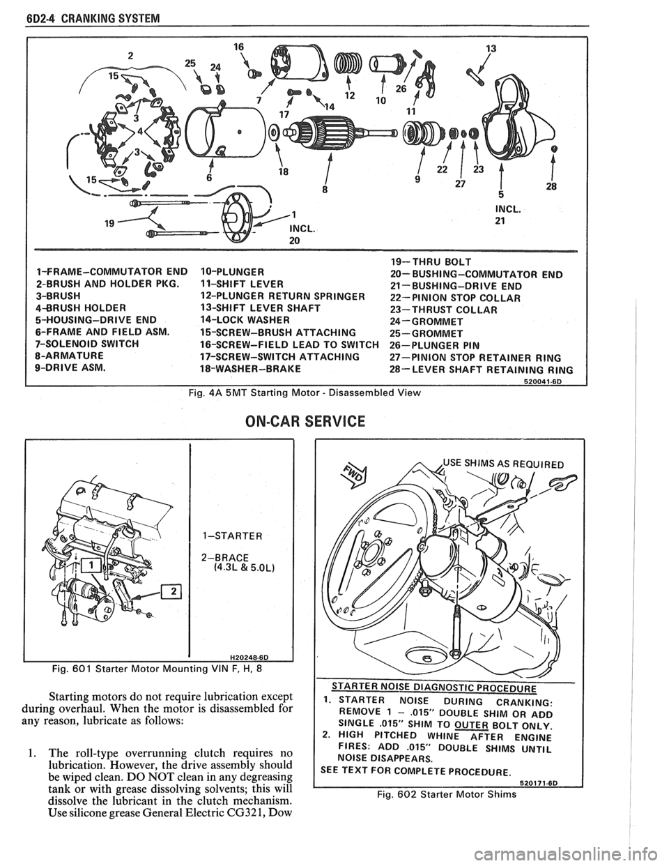
1-FRAME-COMMUTATOR END
2-BRUSH AND HOLDER PKG.
3-BRUSH
4BRUSH HOLDER
5-HOUSING-DRIVE END
6-FRAME AND FIELD ASM.
7-SOLENOID SWITCH
8-ARMATURE
9-DRIVE ASM. 10-PLUNGER
1 1-SHIFT
LEVER
12-PLUNGER RETURN SPRINGER
13-SHIFT LEVER SHAFT
14-LOCK WASHER
15-SCREW-BRUSH ATTACHING
16-SCREW-FIELD LEAD TO SWITCH
17-SCREW-SWITCH ATTACHING
18-WASHER-BRAKE 19-THRU
BOLT
20- BUSHI NG-COMMUTATOR END
21- BUSHING-DRIVE END
22- PINION STOP COLLAR
23-THRUST COLLAR
24-GROMMET
25-GROMMET
26-PLUNGER PIN
27-PINION STOP RETAINER
RING
28-LEVER SHAFT RETAINING RING
Fig. 4A 5MT Starting Motor - Disassembled View
ON-CAR
H20248-6D
Fig. 601 Starter Motor Mounting VIN F, H, 8
Starting motors do not require lubrication except
during overhaul. When the motor is disassembled for
any reason, lubricate as follows:
1. The roll-type overrunning clutch requires no
lubrication. However, the drive assembly should
be wiped clean. DO NOT clean in any degreasing
tank or with grease dissolving solvents; this will
dissolve the lubricant in the clutch mechanism.
Use silicone grease General Electric
CG32 1, Dow
SERVICE
. - . . . - - . REMOVE 1 - ,015" DOUBLE SHIM OR ADD
SINGLE
.015" SHIM TO OUTER BOLT ONLY.
2. HIGH PITCHED WHINE AFTER ENGINE
FIRES: ADD
.015" DOUBLE SHIMS UNTIL
NOISE DISAPPEARS.
SEE TEXT FOR COMPLETE PROCEDURE.
Fig. 602 Starter Motor Shims
Page 456 of 1825
CRANKING SYSTEM 882-5
Corning 33 Medium or equivalent, on the shaft
underneath the overrunning clutch assembly.
2. Avoid excessive lubrication.
STARTER
Use the following procedure to remove the
starter:
1. Disconnect negative battery lead at battery.
2. Raise car.
3. Remove starter braces, shields, etc., that may be
in the way.
4. Remove two starter motor to engine bolts, and
allow starter to drop down.
5. Remove solenoid wires and battery cable and
remove starter.
6. To replace, reverse the above procedure. Ensure
that any shims removed are replaced.
SOLENOID
Use the following procedure to remove the
solenoid from the starter:
1. Disconnect field strap.
2. Remove solenoid to drive housing attaching
screws, motor terminal bolt, and remove solenoid
by twisting.
3. Replace by reversing above procedures.
OVERRUNNING CLUTCH
1. Test overrunning clutch action. The pinion
should turn freely in the overrunning direction.
Check pinion teeth to see that they have not been
chipped, cracked or excessively worn. Replace
assembly if necessary. Badly chipped pinion teeth
may indicate chipped teeth on the ring gear. This
should be checked under such conditions and
replaced if necessary.
2. Check the overrunning clutch for slipping by
leaving the clutch attached to the armature.
Wrap the armature with a shop towel and clamp
the armature in a vise. Using a 12-point deep
socket and torque wrench, put the socket on the
clutch and turn counterclockwise. The clutch
should not slip up to
68 N-m (50 ft. lb.) of torque.
If it does, replace the clutch.
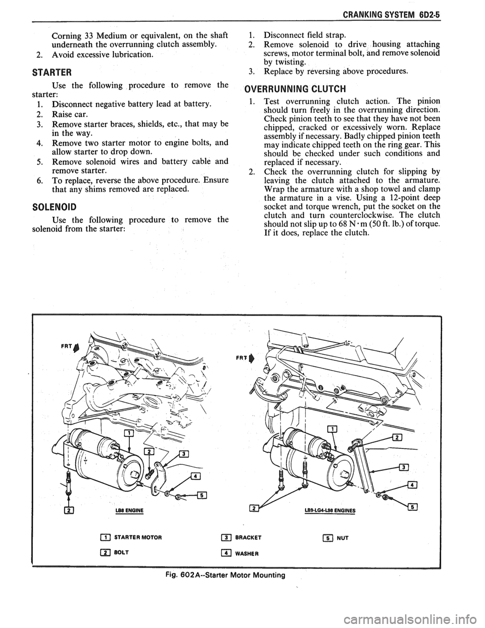
h LB8 ENGINE
a STARTER MOTOR
BOLT
FRT
BRACKET NUT
WASHER
Fig. 602A--Starter Motor Mounting
Page 457 of 1825
6D2-6 CRANKING SYSTEM - -
5MT AND IOMT STARTER MOTORS
DISASSEMBLY, TEST AND REASSEMBLY
(STARTER REMOVED FROM ENGINE)
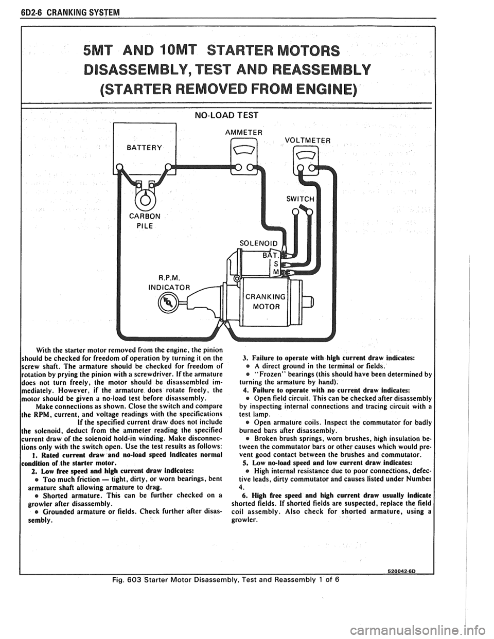
With the starter motor removed from the engine, the pinion
should be checked for freedom of operation by turning it on the
screw shaft. The armature should be checked for freedom of
rotation by prying the pinion with a screwdriver.
If the armature
does not turn freely, the motor should be disassembled im-
mediately. However,
if the armature does rotate freely, the
motor should be given
a no-load test before disassembly.
Make connections as shown. Close the switch and compare
the
RPM, current, and voltage readings with the specifications If the specified current draw does not include
the solenoid, deduct from the ammeter reading the specified
current draw of the solenoid hold-in winding. Make disconnec-
tions only with the switch open. Use the test results as follows:
I. Rat4 current draw and no-load speed Indicates normal
condition of the starter motor.
2. Low free spc4 and high current draw indicates:
e Too much friction - tight, dirty, or worn bearings, bent
armature shaft allowing armature to drag.
e Shorted armature. This can be further checked on a
growler after disassembly.
e Grounded armature or fields. Check further after disas-
sembly.
3. Failure to operate with high current draw indicates: e A direct ground in the terminal or fields.
"Frozen" bearings (this should have been determined by
turning the armature by hand).
4. Failure lo operate with no current draw indicates:
Open field circuit. This can be checked after disassembly
by inspecting internal connections and tracing circuit with
a test lamp.
Open armature coils. Inspect the commutator for badly
burned bars after disassembly.
Broken brush springs, worn brushes, high insulation be-
tween the commutator bars or other causes which would pre-
vent good contact between the brushes and commutator.
5. Low no-loed speed and low current draw indicates:
e High internal resistance due to poor connedtions, defec-
tive leads, dirty commutator and causes listed under Number
4.
6. High free speed and high current draw usually Indicate
shorted fields. If shorted fields are suspected, replace the field
coil assembly. Also check for shorted armature, using
a
growler.
Fig. 603 Starter Motor Disassembly, Test and Reassembly 1 of 6
Page 458 of 1825
CRANKING SYSTEM 602-7
STARTER DISASSEMBLY
RETURN
SOLENOID
DRIVE
GEAR
END FRAME
l NSU LATO R COMMUTATOR
END FRAME
THRUST
- FIBER FIELD FRAME
CLUTCH AND CENTER ARMATURE
DRIVE ASM. BEARING
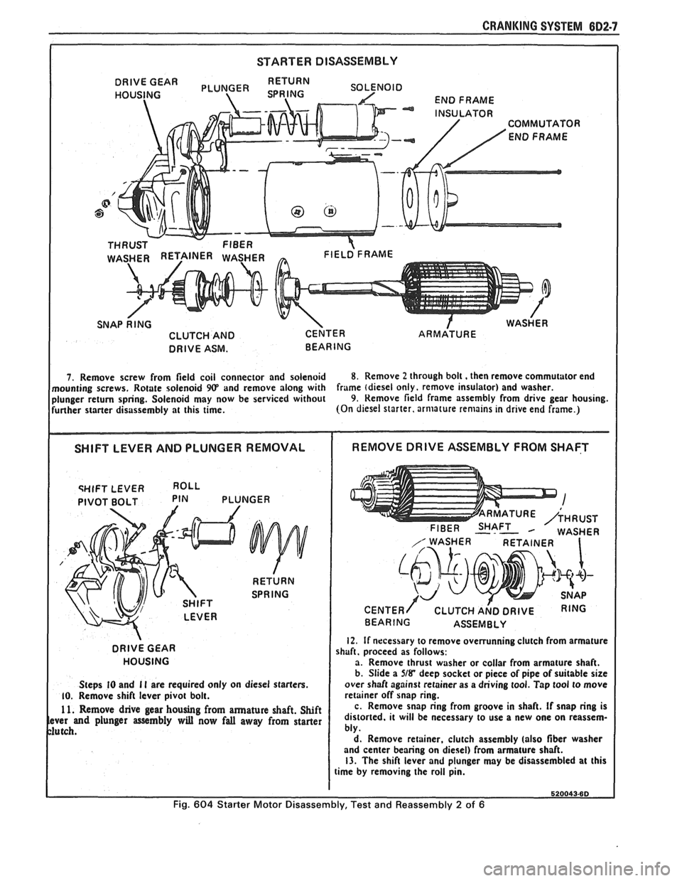
7. Remove screw from field coil connector and solenoid 8. Remove 2 through bolt. then remove commutator end
mounting screws. Rotate solenoid
9(P and remove along with frame
(diesel only. remove insulator) and washer.
plunger return spring. Solenoid may now be serviced without 9. Remove field frame assembly from drive gear housing.
further starter disassembly at this time. (On
diesel starter, armature remains in drive end frame.)
qHIFT LEVER
PIVOT BOLT PIN PLUNGER
DRIVE
GEAR
HOUSING
Steps
I0 and I I are required only on diesel starters. 10. Remove shift lever pivot bolt.
1 1. Remove drive gear housing from armature shaft. Shift ver and plunger assembly will now fall away from starter
utch.
FIBER SHAFT M WASHER
CENTER/ CLUTCH A~D DRIVE RING
BEARING ASSEMBLY
12. If necessary to remove overrunning clutch from armature
shaft. proceed as follows:
a. Remove thrust washer or collar from armature shaft.
b. Slide a
5/8* deep socket or piece of pipe of suitable size
over shaft against retainer as a driving tool. Tap tool to move
retainer off snap ring.
c. Remove snap ring from groove in shaft.
If snap ring is
distorted. it will be necessary to use a new one on reassem-
bly.
d. Remove retainer, clutch assembly (also
fiber washer
and center bearing on diesel) from armature shaft.
13. The shift lever and plunger may be disassembled at this
time by removing the roll pin.
Fig. 604 Starter Motor Disassembly, Test and Reassembly 2 of 6
Page 459 of 1825
682-8 CRANKING SYSTEM
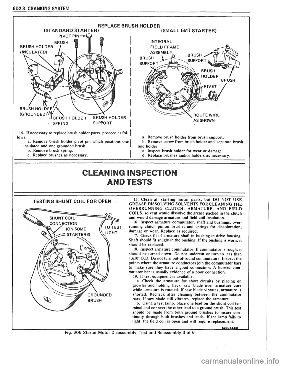
REPLACE BRUSH HOLDER
(SMALL 5MT STARTER)
INTEGRAL ROUTE
WIRE
14. If necessary to replace brush holder pans, proceed as fol- (
CLEANING INSPECTION
AND ""FSTS
GHT damage or wear. Replace as required. 17. Check fit of armature shaft in bushing in drive housing.
Shaft should fit snugly in the bushing. If the bushing is worn, it
should be replaced.
18. Inspect armature commutator. If commutator is rough, it
should be turned down. Do not undercut or turn to less than
1.65U' O.D. Do not turn out-of-round commutators, Inspect the
points where the armature conductors join the commutator bars
to make sure they have a good connection.
A burned com-
mutator bar is usually evidence of a poor connection.
19. If test equipment is available:
a. Check the armature for short circuits by placing on
growler and holding hack saw blade over armature core
while armature is rotated. If saw blade vibrates, armature is
shorted. Recheck after cleaning between the commutator
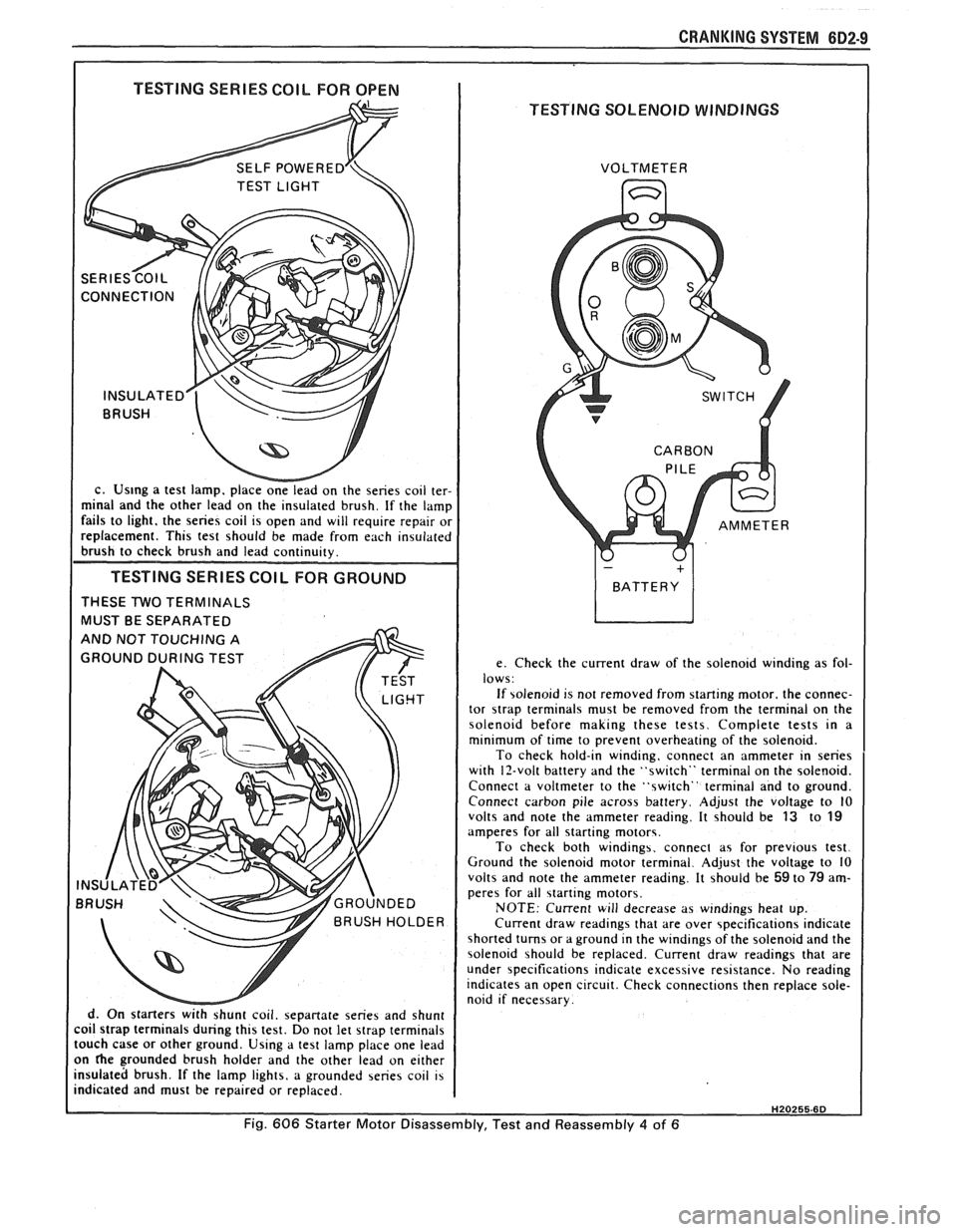
bars. If saw blade still vibrates. replace the armature.
b. Using a test lamp. place one lead on the shunt coil ter-
minal and connect the other lead to a ground brush. This test
should
be made from both ground brushes to insure con-
Fig. 605 Starter Motor Disassembly, Test and Reassembly 3 of 6
Page 460 of 1825
CRANKING SYSTEM BD2-9
I TESTING SERIES COIL FOR OPEN I
TESTING SOLENOID WINDINGS
c. Us~ng a test lamp. place onelead on the series coil ter-
minal and the other lead on the insulated brush. If the lamp
fails to light. the series coil is open and will require repair or
replacement. This test should be made from each insulated
brush to check brush and lead continuity.
TESTING SERIES COlL FOR GROUND
THESE TWO TERMINALS
MUST BE SEPARATED
d. On starters
withshunt coil. sepanate series and shunt
coil strap terminals during this test. Do not let strap terminals
touch case or other ground. Using a test lamp place one lead
on
he grounded brush holder and the other lead on either
insulated brush. If the lamp lights, a grounded series coil is
indicated and must be repaired or replaced. VOLTMETER
e. Check the current draw of the solenoid winding as fol-
lows:
If solenoid is not removed from starting motor. the connec-
tor
strap terminals must be removed from the terminal on the
solenoid before making these tests. Complete tests in a
minimum of time to prevent overheating of the solenoid.
To check hold-in winding, connect an ammeter in series
with 12-volt battery and the "switch" terminal on the solenoid.
Connect a voltmeter to the "switch" terminal and to ground.
Connect carbon pile across battery. Adjust the voltage to
10 volts and note the ammeter reading. It should be 13 to 19 amperes for all starting motors.
To check both windings. connect as for previous test.
Ground the solenoid motor terminal. Adjust the voltage to 10
volts and note the ammeter reading. It should be
59 to 79 am-
peres for all starting motors.
NOTE: Current will decrease as windings heat up.
Current draw readings that are over specifications indicate
shorted turns or a ground in the windings of the solenoid and the
solenoid should be replaced. Current draw readings that are
under specifications indicate excessive resistance. No reading
indicates an open circuit. Check connections then replace sole-
noid if necessary.
H20255.6D
Fig. 606 Starter Motor Disassembly, Test and Reassembly 4 of 6