RENAULT KANGOO 1997 KC / 1.G Chassis Workshop Manual
Manufacturer: RENAULT, Model Year: 1997, Model line: KANGOO, Model: RENAULT KANGOO 1997 KC / 1.GPages: 105
Page 101 of 105
ELECTRONICALLY CONTROLLED HYDRAULIC SYSTEMS
BOSCH ABS
38
PRN3813
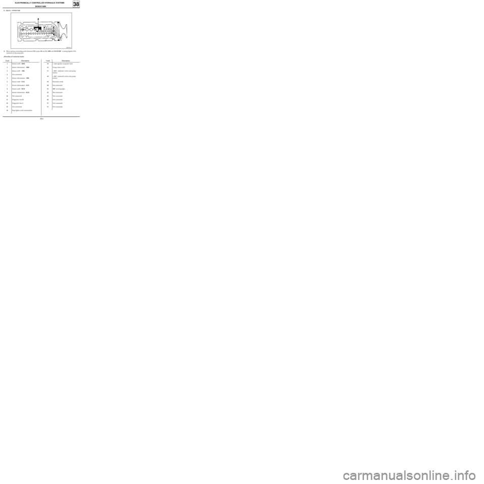
31 TRACK CONNECTOR
Track Description
1
2
3
4
5
6
7
8
9
10
11
12
13
14Sensor earth - RRH
Sensor information -
RRH
Sensor earth - FRH
Not connected
Sensor information -
FRH
Sensor earth - FLH
Sensor information - FLH
Sensor earth - RLH
Sensor information - RLH
Not connected
Diagnostic line K
Diagnostic line L
Not connected
Stop lights switch information
AMicro-spring connecting earth (terminal 19) to pins 20 and 21 (ABS and NIVOCODE warning lights) if the
connector is disconnected.
Allocation of connector tracks
Track Description
15
16
17
18
19
20
21
22
25
26
27
31+ after ignition computer feed
Pump motor earth
+ BAT (solenoid valves and pump
motor)
+ BAT (solenoid valves and pump
motor)
Electronic earth
Not connected
ABS warning light
Not connected
Not connected
Not connected
Not connected
Not connected
38-6
Page 102 of 105
ELECTRONICALLY CONTROLLED HYDRAULIC SYSTEMS
BOSCH ABS
38
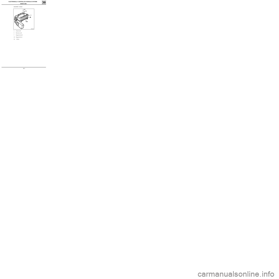
DIAGNOSTIC SOCKET
PRN3807
4Chassis earth
5Electronic earth
7Diagnostic line K
15Diagnostic line L
16+ battery
38-7
Page 103 of 105
ELECTRONICALLY CONTROLLED HYDRAULIC SYSTEMS
BOSCH ABS
38
13138R
Pipe unions M10 × 100 1.7
M12 × 100 1.7
TIGHTENING TORQUES (in daN.m)
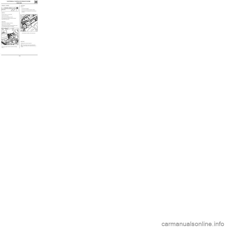
REMOVAL
Put the vehicle on a two post lift.
Disconnect the battery.
Remove the front right hand wheel.
Fit a pedal press to limit the amount of brake
fluid which will run out.
From above:
Disconnect the computer connector.
Remove the two earth bolts.
Disconnect the six pipes from the hydraulic assem-
bly, marking their position for refitting.
From below:
Remove:
- the exhaust downpipe,
- the exhaust manifold heat shield ( 3 bolts),
- the two lower mounting bolts for the hydraulic
assembly,HYDRAULIC ASSEMBLY
13139R
- the hydraulic assembly via the wheel arch.
Remove the upper hydraulic assembly mounting
bolt ( 1 ).
REFITTING
Refitting is the reverse of removal.
NOTE : the computer must not be removed. If
there is a fault, replace the complete hydraulic as-
sembly.
38-8
Page 104 of 105
ELECTRONICALLY CONTROLLED HYDRAULIC SYSTEMS
BOSCH ABS
38
HYDRAULIC BRAKING TEST
This section describes the test to be carried out using the XR25, to check the mounting of the ABS system in
the vehicle and, in particular, the hydraulic circuit.
NOTE: for this test, two persons are required and the vehicle must be on a two post lift, if possible.
Principle of the test
Put the vehicle on the lift with the wheel to be tested raised. One of the operators must be in the passenger
compartment in the driver’s position with the XR25. Switch the ignition on, vehicle in neutral, in fault finding
mode and press the brake pedal. The second operator must apply a torque to the wheel to try and rotate it.
The operator generates an appropriate command on the XR25 which carries out the following cycle ten
times: alternate decrease then increase in pressure at the wheel to be checked. These actions in the ABS will
be noted at the wheel as ten alternate locking and releasing operations. The jerky movement of the wheel,
noted qualitatively by the operator, signify that the hydraulic circuit for this wheel is correctly connected.
The programme for the XR25 for this sequence is as follows:
- Cycle on the wheel to be tested:
- a drop in pressure for 200 ms where the pump starts at the same time,
- an increase in pressure for 300 ms where the pump starts at the same time (ten cycles are carried out
for the wheel in question).
- The pressure increases to master cylinder pressure for all four wheels.
- The hydraulic pump motor stops.
- The operator releases the brake pedal.
The hydraulic test for the wheel in question is complete - begin the test for the three other wheels.
BLEEDING PROCEDURE
NOTE :
the hydraulic assembly is pre-filled.
This bleeding procedure must be used when one of the following components has been removed:
- the hydraulic assembly,
- the master cylinder,
- the pipework (between the hydraulic assembly and the master cylinder).
1)Bleed the braking system conventionally using the pedal.
NOTE : if, after a road test with ABS regulation, the pedal travel is not correct, bleed the hydraulic assembly.
38-9
Page 105 of 105
ELECTRONICALLY CONTROLLED HYDRAULIC SYSTEMS
BOSCH ABS
38
2)Bleeding the hydraulic assembly.
IMPORTANT : the bleeding order must be observed, beginning with the rear right , then the rear left, front
left and then front right.
a)Bleed the rear right brake by bleeding the hydraulic assembly secondary circuit using the XR25:
- position the bleed container and the hose, open the brake bleed screw,
- pump the brake pedal (approximately ten times),
- start the bleed command on the
XR25,
- pump the brake pedal during the diagnostic bleed phase,
- at the end of the bleed cycle on the
XR25, continue to pump the brake pedal and close the brake
bleed screw.
b)Carry out the procedure described at a) for the rear left, front left and front right brakes.
c)Check the pedal travel and if it is incorrect, restart the bleeding procedure.
IMPORTANT : ensure there is sufficient brake fluid in the reservoir.
CHECKING THE WHEEL SPEED SENSORS
a)Check the resistance of the sensor connections (from the computer connector to the 2 track speed sensor
connector).
b)Visually inspect the teeth ( 26 teeth) on the target and if they are faulty, replace the target.
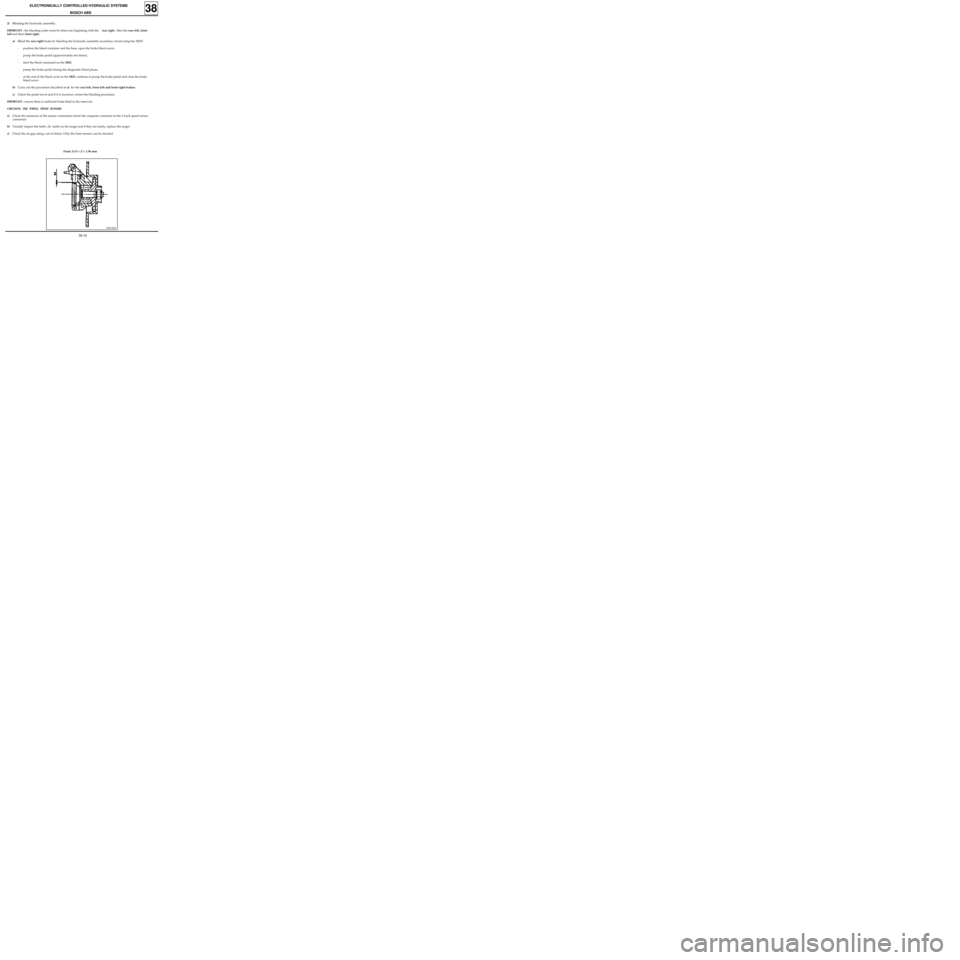
c)Check the air gap using a set of shims. Only the front sensors can be checked.
PRN3820
Front: 0.13 < Z < 1.96 mm
38-10