RENAULT KANGOO 1997 KC / 1.G Chassis Manual Online
KANGOO 1997 KC / 1.G
RENAULT
RENAULT
https://www.carmanualsonline.info/img/7/1734/w960_1734-0.png
RENAULT KANGOO 1997 KC / 1.G Chassis Manual Online
Trending: airbag off, transmission, fuse diagram, instrument panel, power steering, service, diagram
Page 81 of 105
12865-1R
MECHANICAL ELEMENT CONTROLS
Braking compensator
37
Carry out the same operation on the other circuit:
- one at the front left hand side,
- one at the rear right hand side.
If there is a large difference (values exceed
tolerance ranges), replace the compensator since
no repair is permitted.ADJUSTMENT
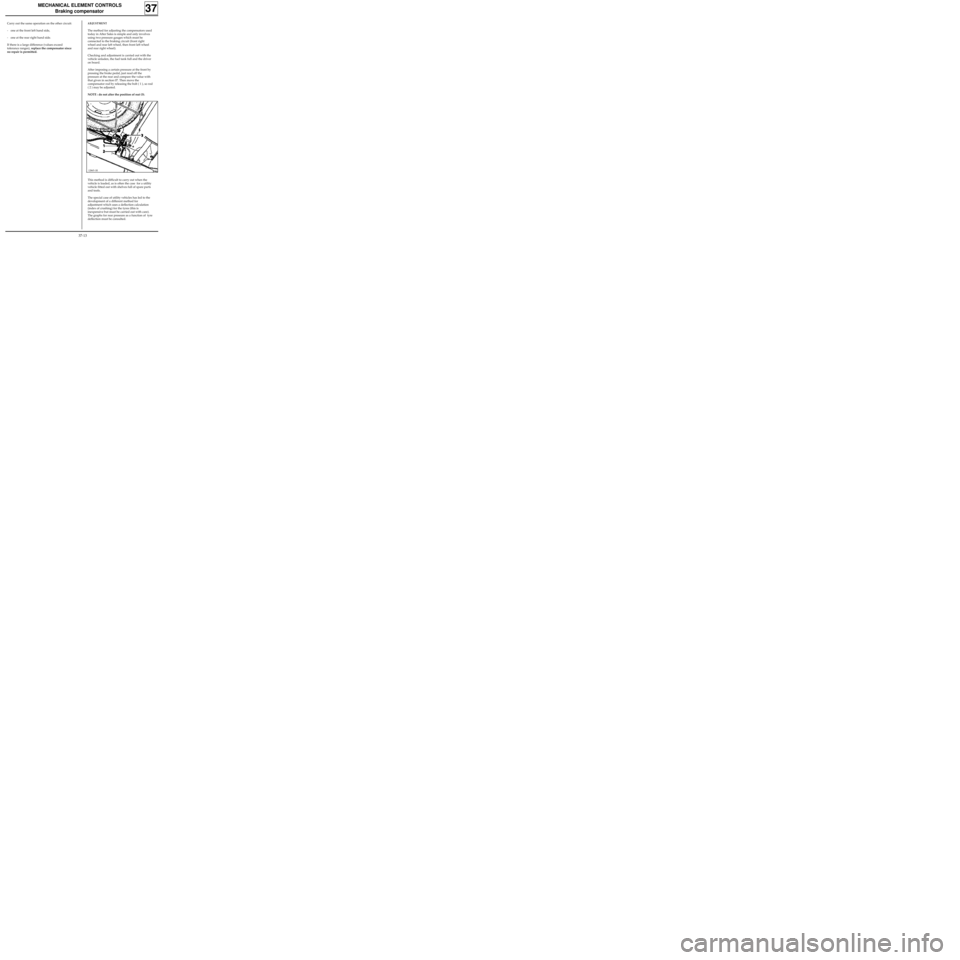
The method for adjusting the compensators used
today in After Sales is simple and only involves
using two pressure gauges which must be
connected to the braking circuit (front right
wheel and rear left wheel, then front left wheel
and rear right wheel).
Checking and adjustment is carried out with the
vehicle unladen, the fuel tank full and the driver
on board.
After imposing a certain pressure at the front by
pressing the brake pedal, just read off the
pressure at the rear and compare the value with
that given in section 07. Then move the
compensator rod by releasing the bolt ( 1 ), so rod
( 2 ) may be adjusted.
NOTE : do not alter the position of nut (3).
This method is difficult to carry out when the
vehicle is loaded, as is often the case for a utility
vehicle fitted out with shelves full of spare parts
and tools.
The special case of utility vehicles has led to the
development of a different method for
adjustment which uses a deflection calculation
(index of crushing) for the tyres (this is
inexpensive but must be carried out with care).
The graphs for rear pressure as a function of tyre
deflection must be consulted.
37-13
Page 82 of 105
MECHANICAL ELEMENT CONTROLS
Braking compensator
37
Tooling required:
- one measuring tape mounted on a base (used
for measuring underbody heights),
- an accurate pressure gauge.
1• Preparation of the vehicle:
- the vehicle must be left loaded,
- the person in charge of pressing the brake
pedal when the compensator is being adjusted
must be in the vehicle when the radius under
load is measured at the rear wheels,
- the vehicle must be on a flat horizontal surface,
which is smooth and clean (use a four post lift if
possible).
2• Marking the centre of the rear wheels:
- lift the rear of the vehicle so the rear wheels
may be turned,
- apply a chalk stick to the hub cover or the
wheel embellisher at the approximate centre of
the wheel,
- turn the wheel by hand fairly quickly, pressing
hard on the chalk. This allows concentric circles
to be drawn around the real rotation centre of
the wheel,
- mark the centre using a pencil on the chalk,
- carry out the same operation on the second
rear wheel.3• Adjusting the rear tyre pressure:
- the pressure must be adjusted with the wheels
on the ground and one person in the driver’s
seat,
- deflate the two rear wheels so that the pressure
is brought to 1.2 bar (use an accurate pressure
gauge which has been correctly calibrated),
- wait a few minutes for the air in the tyres to
return to ambient temperature since it is
cooled when the tyres are deflated and the
pressure will therefore have changed,
- adjust the pressure to 1.2 bar as accurately as
possible.
4• Measuring the radius with the vehicle
unladen:
- lift the rear wheels so that the tyres are no
longer crushed by the load on the axle (as soon
as the wheels leave the ground),
- measure the distance between the ground and
the wheel centre using the measuring tape.
5• Measuring the radius with the rear wheels
loaded:
- return the vehicle to its wheels,
- measure the distance between the ground and
the wheel centre using the measuring tape.
37-14
Page 83 of 105
MECHANICAL ELEMENT CONTROLS
Braking compensator
37
6• Calculating the tyre deflection:
- subtract the two measurements made to obtain
the tyre deflection.
7• Carry out stages 4, 5 and 6 for the other rear
wheel.
8• Calculate the average deflection for both
tyres:
- add the two values for the two deflections
noted for the two rear wheels and divide the
result by two to give the average deflection.
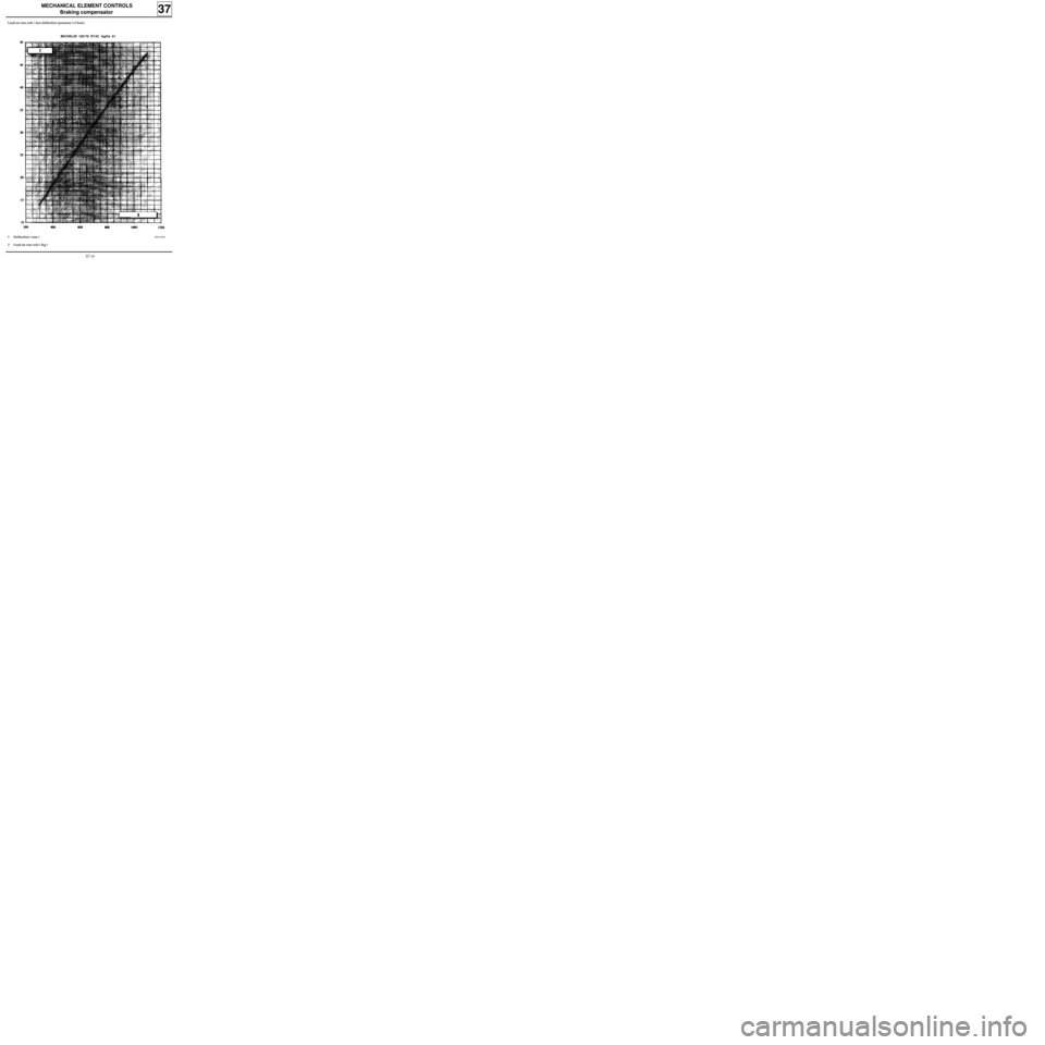
9• Reading the graphs:
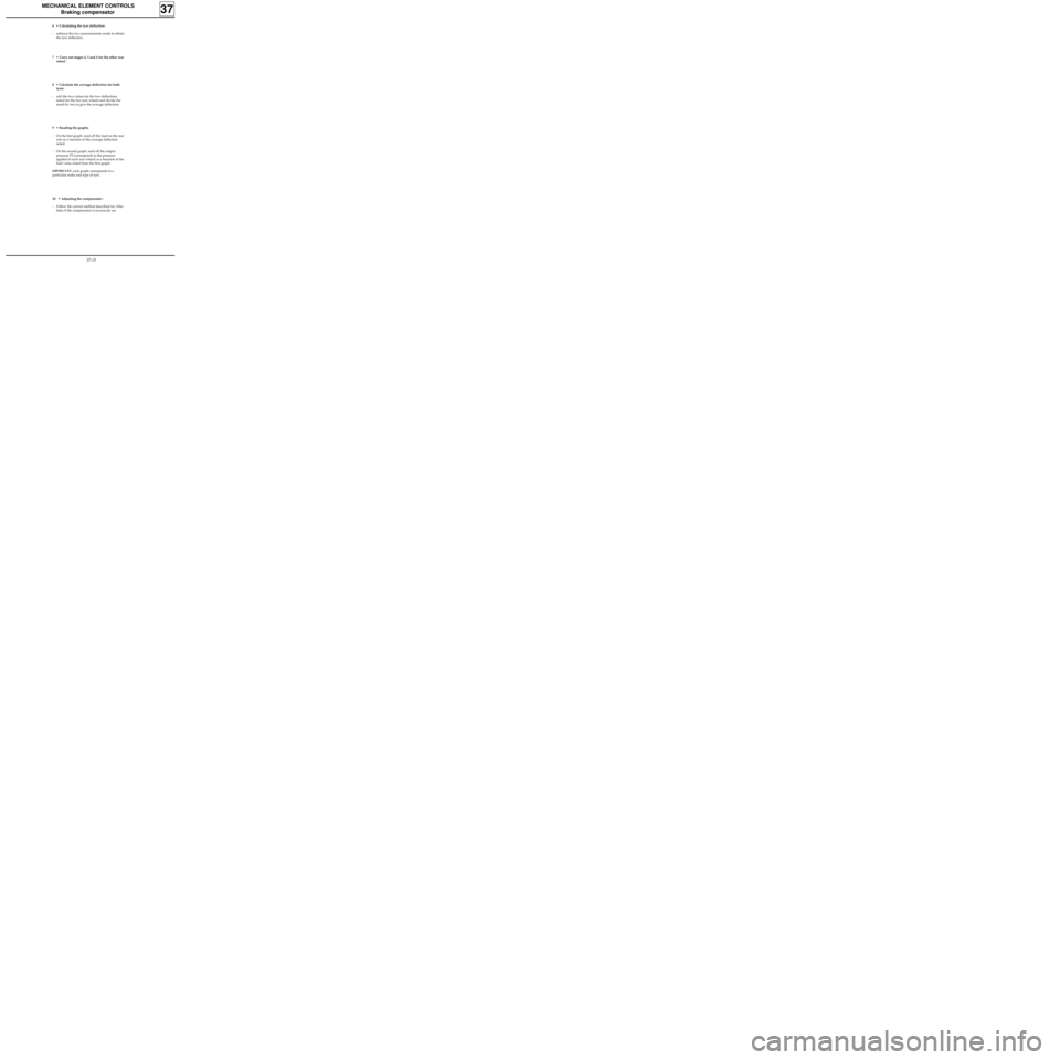
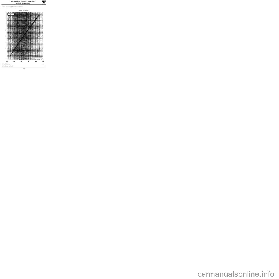
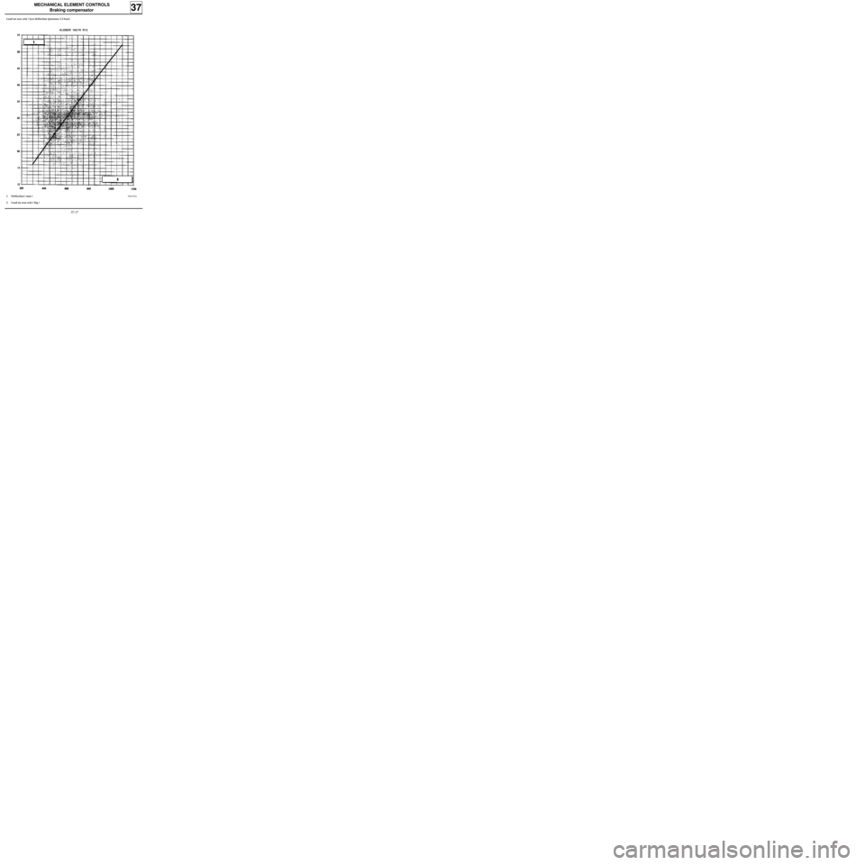
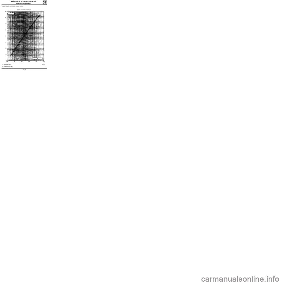
- On the first graph, read off the load on the rear
axle as a function of the average deflection
noted.
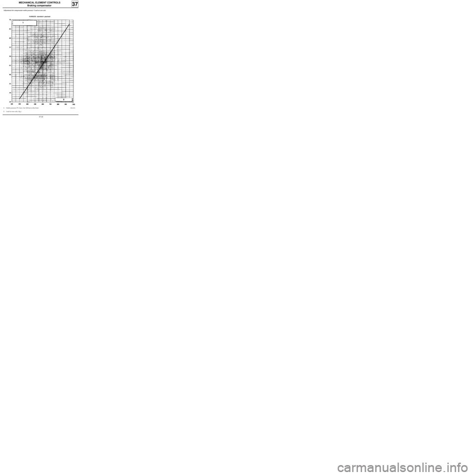
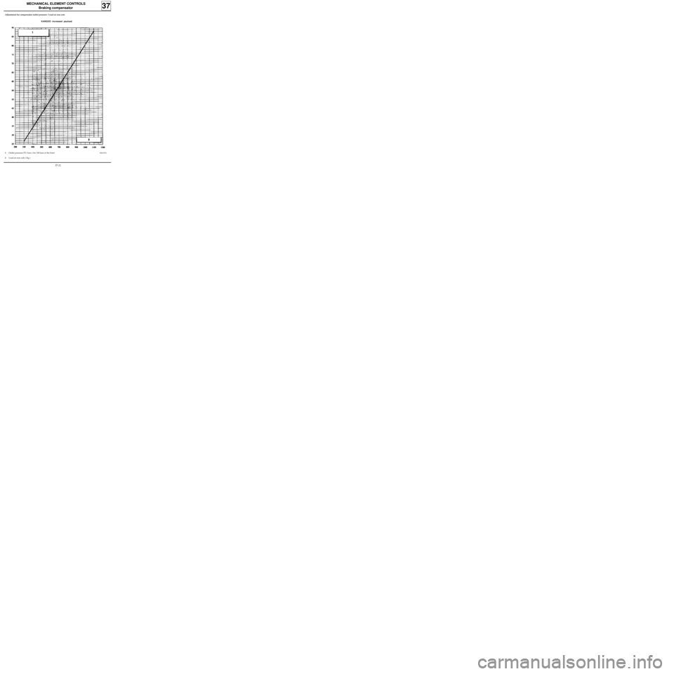
- On the second graph, read off the output
pressure P2 (corresponds to the pressure
applied to each rear wheel) as a function of the
load value noted from the first graph.
IMPORTANT: each graph corresponds to a
particular make and type of tyre.
10 • Adjusting the compensator :
- Follow the current method described for After
Sales if the compensator is incorrectly set.
37-15
Page 84 of 105
MECHANICAL ELEMENT CONTROLS
Braking compensator
37
Load on rear axle / tyre deflection (pressure 1.2 bars)
DUNLOP 165/70 R13C
PRN37001 Deflection ( mm )
2 Load on rear axle ( Kg )
37-16
Page 85 of 105
MECHANICAL ELEMENT CONTROLS
Braking compensator
37
Load on rear axle / tyre deflection (pressure 1.2 bars)
KLEBER 165/70 R13
PRN37041 Deflection ( mm )
2 Load on rear axle ( Kg )
37-17
Page 86 of 105
MECHANICAL ELEMENT CONTROLS
Braking compensator
37
Load on rear axle / tyre deflection (pressure 1.2 bars)
MICHELIN 165/70 R13C XC4S
PRN37001 Deflection ( mm )
2 Load on rear axle ( Kg )
37-18
Page 87 of 105
MECHANICAL ELEMENT CONTROLS
Braking compensator
37
Load on rear axle / tyre deflection (pressure 1.2 bars)
MICHELIN 165/70 R13C Agilis 61
PRN37001 Deflection ( mm )
2 Load on rear axle ( Kg )
37-19
Page 88 of 105
MECHANICAL ELEMENT CONTROLS
Braking compensator
37
Adjustment for compensator outlet pressure / Load on rear axle
KANGOO standard payload
PRN37021 Outlet pressure P2 ( bars ) for 100 bars at the front
2 Load on rear axle ( Kg )
37-20
Page 89 of 105
MECHANICAL ELEMENT CONTROLS
Braking compensator
37
PRN37031 Outlet pressure P2 ( bars ) for 100 bars at the front
2 Load on rear axle ( Kg )
Adjustment for compensator outlet pressure / Load on rear axle
KANGOO increased payload
37-21
Page 90 of 105
MECHANICAL ELEMENT CONTROLS
Clutch control cable
37
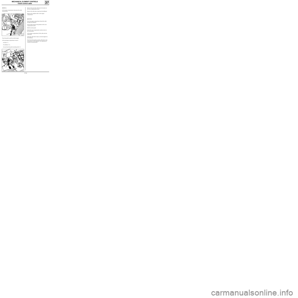
REMOVAL
In the engine compartment, disconnect the cable
from the fork.
89204S
12986R
Remove the end of the cable from its location on
the wear compensation sector.
Remove the cable sleeve stop from the bulkhead.
Remove the complete cable via the engine
compartment.
REFITTING
From the engine compartment, thread the cable
through the bulkhead.
Fit the cable end piece into position on the wear
compensation sector.
Refit the clutch pedal.
Check the wear compensation ratchets return to
the rest position.
In the engine compartment, fit the cable onto the
clutch fork.
Check the cable sleeve stop is correctly aligned on
the bulkhead.
Press the clutch pedal to clip the cable sleeve stop
into position on the bulkhead. The adjustment is
carried out automatically.
Press the pedal to pull the cable through.
In the passenger compartment, remove:
- the bolt ( 1 ),
- the stiffener ( 2 ),
- the nut from the pedal mounting shaft ( 3 ).
37-22
Trending: battery, wheel bolt torque, suspension, horn, gearbox, dimensions, width


