engine RENAULT KANGOO 1997 KC / 1.G Engine And Peripherals Workshop Manual
[x] Cancel search | Manufacturer: RENAULT, Model Year: 1997, Model line: KANGOO, Model: RENAULT KANGOO 1997 KC / 1.GPages: 208
Page 137 of 208
ANTIPOLLUTION
Exhaust gas recirculation (EGR)
14
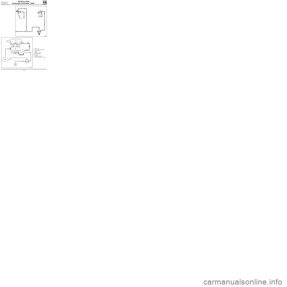
1 EGR valve
2 EGR solenoid (ON/OFF)
3 Vacuum pump
4 Engine
5 Exhaust manifold
6 Inlet manifold
7 Air filter
8 Injection computer
9 Coolant temperature sensor
13046R
F8Q Engine
13045R
14-11
Page 138 of 208
ANTIPOLLUTION
Exhaust gas recirculation (EGR)
14
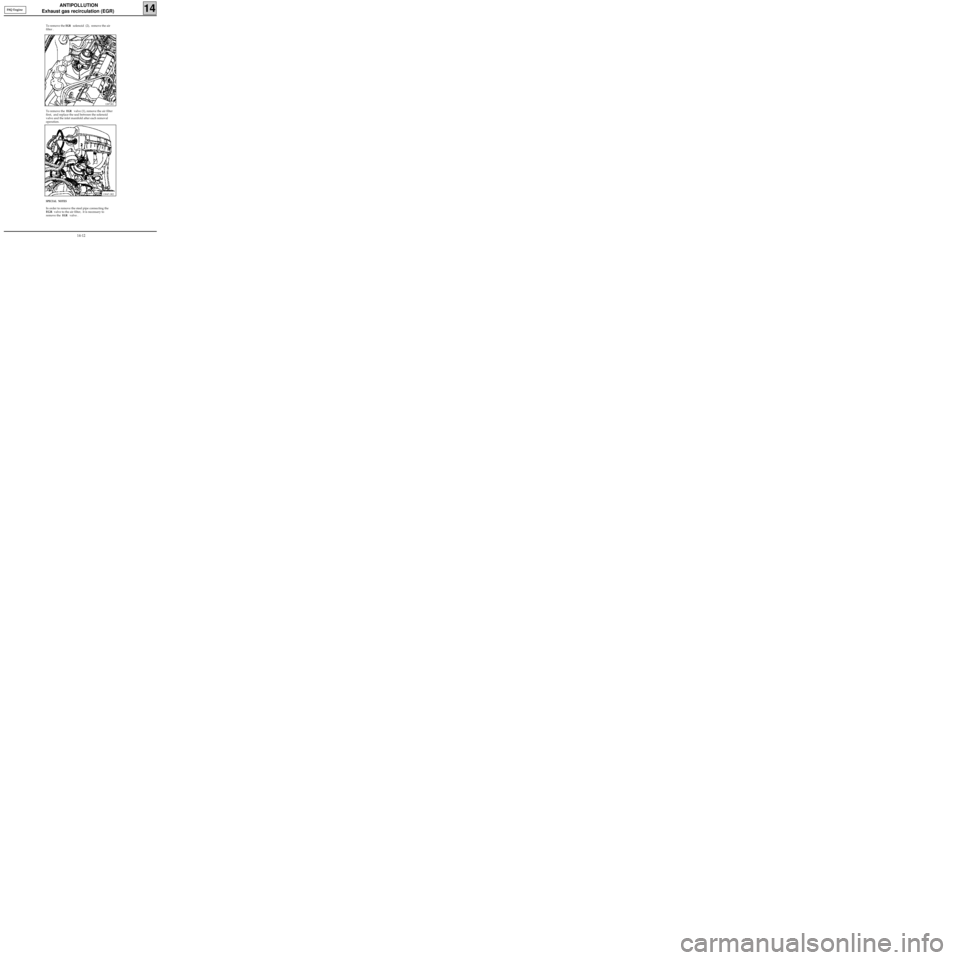
SPECIAL NOTES
In order to remove the steel pipe connecting the
EGR valve to the air filter, it is necessary to
remove the
EGR valve .
12871R1
F8Q Engine
13047-1R2
To remove the EGR solenoid (2), remove the air
filter .
To remove the
EGR valve (1), remove the air filter
first, and replace the seal between the solenoid
valve and the inlet manifold after each removal
operation.
14-12
Page 139 of 208
ANTIPOLLUTION
Exhaust gas recirculation (EGR)
14
The EGR is controlled by the computer via an
ON/OFF solenoid valve.
The operation of the
EGR solenoid valve is de-
pendent upon the following parameters :
- the air temperature,
- the coolant temperature ,
- the altitude,
- the position of the load lever ,
- the vehicle speed ,
- the engine speed .
The EGR function is cut if :
- the air temperature < 16°C or
- the coolant temperature < 45°C or
- the engine speed/ load potentiometer value is
greater than a certain threshold .
The EGR is cut after operating at idle speed for 40
seconds (at zero vehicle speed).
Once the vehicle speed > 25 mph (40 km/h), the
EGR is operational again. It will be cut again after
40 seconds of operating at idle speed at zero ve-
hicle speed.
XR 25 bargraph 14 RH is illuminated if the EGR
function is permitted. In order to determine if the
EGR is actually controlled, use #24. if the value is
different from 0, the EGR is activated . F8Q Engine
14-13
Page 140 of 208
CHECKING
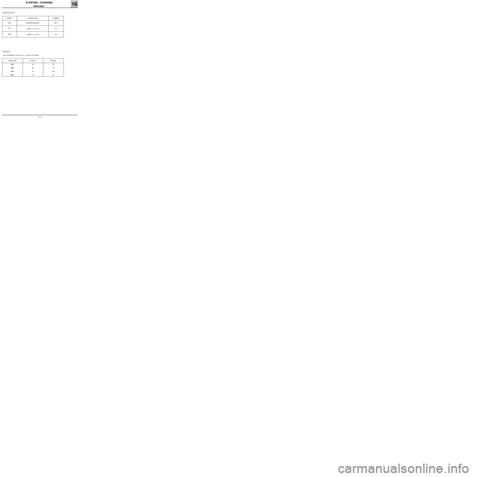
After 15 minutes warming up at a voltage of 13.5 volts.
STARTING - CHARGING
Alternator
16
IDENTIFICATION
ENGINE ALTERNATOR CURRENT
D7F DELPHI 104 802 215 80 A
E7J
VALEO A 11 VI 8775 A
F8Q
VALEO A 11 VI 8875 A
Engine rpm 75 amps 80 amps
1000
2000
3000
400046
68
71
7254
75
80
82
16-1
Page 141 of 208
STARTING - CHARGING
Alternator
16
OPERATION - FAULT FINDING
These vehicles are equipped with alternators with
internal ventilation and integral regulator, also
with a warning light on the instrument panel
which has the following functions :
- when the ignition is switched on, the light illu-
minates
- when the engine is started the light extin-
guishes,
- if the light illuminates whilst the engine is
running there is a "charging "fault.
LOOKING FOR FAULTS
The warning light does not illuminate when the
ignition is switched on.
Check:
- all electrical connections are good.
- the bulb has not blown. (Earth the circuit and
the bulb should illuminate).
The warning light illuminates when the engine is
running.
This indicates a charging fault which could be
caused by :
- the alternator drive belt being broken or the
charging wiring being cut,
- internal alternator damage (rotor, stator,
diodes or brush),
- a regulator fault,
- excess voltage.The customer complains of a lack of charge and
the warning light is operating correctly.
If the regulated voltage is less than 13.5 V, check
the alternator. The fault could be caused by :
- a diode which has been damaged,
- a phase which is cut,
- contaminated or worn tracks.
Checking the voltage
Connect a voltmeter across the battery terminals
and read the battery voltage.
Start the engine and increase the engine speed
until the needle registers a stable regulated
voltage.
This voltage should be between 13.5 V and 14.8 V.
Connect as many consumers as possible, the
regulated voltage should be between 13.5 V and
14.8 V.
IMPORTANT: if arc welding work is to be carried
out on the vehicle, the battery and regulator
must be disconnected.
16-2
Page 142 of 208
STARTING - CHARGING
Alternator
16
OPTIMA 5800 Diagnostic station
CHECKING THE CHARGING CIRCUIT USING THE DIAGNOSTIC STATION
The OPTIMA 5800 diagnostic station allows the alternator to be checked by measuring the voltage and cur-
rent delivered , with or without electrical consumers .
NOTE : the Amps clamp used for this station is of the inductive type (measurement range: 0 to 1 000 A). It
is fitted without disconnecting the battery, which allows the the computer memory and adaptive informa-
tion to be saved.
Fit the Amps clamp directly at the alternator output, with the arrow pointing towards the alternator (any in-
correct positioning is detected by the station).
The measurement is carried out in three stages :
- measurement of the battery voltage, ignition off,
- measurement of the regulated voltage and of the current supplied, without consumers,
- measurement of the regulated voltage and current supplied, with a maximum number of consumers.
On completion of the test, the values noted will lead to the following fault finding messages :
- Battery voltage, no load < 12.3 V = battery uncharged.
Without consumers :
- Regulated voltage > 14,8 V = > regulator faulty ,
- (regulated voltage, no load < 13.2 V) or (charging current< 2 A) = >charging fault.
With consumers :
- Regulated voltage > 14.8 V = > regulator faulty,
- Regulated voltage < 12.7 V = > it is necessary to check the alternator supply in relation to its specifica-
tions :
Engine
Current (amps)D7F E7J F8Q
Nominal current 70 75 75
Minimum current which the alternator must
supply, all consumers connected 53 51 55
FAULT FINDING
SPECIAL TOOLING REQUIRED
16-3
Page 143 of 208
STARTING - CHARGING
Alternator
16
If the electrical supply measured is too low, check:
- the wear of the alternator (brush...),
- the battery connections,
- the engine earth strap,
- the conformity of the alternator,
- the belt tension.
If the electrical supply measured is correct and the regulated voltage is too low, the alternator is not faulty.
The cause of the problem is to be attributed to one of the following sources :
- the vehicle has too many electrical consumers,
- the battery is discharged.
FAULT FINDING (continued)
16-4
Page 144 of 208
STARTING-CHARGING
Alternator
16
REMOVAL
Place the vehicle on a two post lift .
Disconnect the battery as well as all electrical
connections leading to the alternator.
Remove :
- the alternator belt and that of the power as-
sisted steering pump for the D7F engine (if
fitted),
- the alternator.
REFITTING
Refitting is the reverse of removal.
D7F Engine
Tensioning of the alternator belt is carried out
using the locally manufactured tool shown be-
low (threaded rod 100 mm in length (X) and three
M6 nuts).
D7F / E7J
Engines
SPECIAL TOOLING REQUIRED
Mot. 1273 Tool for checking belt tension
10617R
E7J Engine
Tension the belt using the bolt at (1) and tighten
the nut at (2) , having measured the tension.
13363R
See section 07 "Accessories belt tension" for the
tension values.
16-5
Page 145 of 208
STARTING-CHARGING
Alternator
16
REMOVAL
Place the vehicle on a two post lift.
Disconnect the battery as well as all electrical
connections leading the alternator.
Remove :
- the front right wheel arch,
- the alternator mountings as well as the belt,
- the support (A),
SPECIAL TOOLING REQUIRED
Mot. 1273 Tool for checking belt tension
13092R
- the cross member mounting bolts and remove
it in order to remove the alternator.
13188S
REFITTING
Refitting is the reverse of removal.
See section 07 "Accessories belt tension" for the
tension values. F8Q Engine
16-6
Page 146 of 208

STARTING - CHARGING
Starter motor
16
ENGINE STARTER MOTOR
D7FVALEO D7 E1
Bosch 0001116001
E7J
D6 RA 73
F8Q Bosch 0001108180
IDENTIFICATION
16-7