engine RENAULT KANGOO 1997 KC / 1.G Engine And Peripherals Workshop Manual
[x] Cancel search | Manufacturer: RENAULT, Model Year: 1997, Model line: KANGOO, Model: RENAULT KANGOO 1997 KC / 1.GPages: 208
Page 115 of 208

DIESEL EQUIPMENT
Fast idle speed control
13
- if the engine speed falls to 650 rpm and the
vehicle speed is lower than 15 mph (25 km/h)
(engine start improvement programming).
The fast idle speed is cut off once the speed
becomes > 850 rpm
NOTE :
- Fast idle speed operational :
• solenoid valve not operated,
• cable loose, and not tensioned.
- Nominal idle sped :
• solenoid valve operated
• cable tensioned
SPECIAL FEATURES : once the AC has been
selected on the instrument panel, the fast idle
speed function is activated. The fast idle speed function is controlled by the
computer via a solenoid valve operating the dia-
phragm (versions with or without air conditio-
ning).
The fast idle speed control becomes operational :
- if, on switching on the ignition, the coolant
temperature is below 10°C,
Coolant
temperature
on switching
ignition on (°C)Fast idle speed
cut-off
temperature
(°C) Fast idle speed
cut-off
temperature
(°C)
10
5
0
- 10
- 2020
20
30
40
5011
15
20
25
30
F8Q 662F8Q 630
13-35
Page 116 of 208
DIESEL EQUIPMENT
Injection/air conditioning programming
13
CONNECTION BETWEEN AIR CONDITIONING ASSEMBLY AND INJECTION COMPUTER
The electrical connection :
- from the air conditioning computer to the diesel injection computer consists of one wire. This track only
carries the information that the AC is operating. From this, the diesel injection computer deduces the AC
selection information : track 11,
- from the diesel injection computer to the air conditioning computer consists of one wire. This track
carries all information regarding authorising and preventing operation of the compressor : track 19.
COMPRESSOR OPERATION PROGRAMMING
During certain stages of operation, the diesel injection computer stops the compressor from functioning.
Engine start programming
After the engine has started running, the compressor is prevented from functioning for 3 seconds.
Performance return programming
If the full load position is detected, the AC compressor is prevented from functioning for 8 seconds.
Stalling prevention programming
If the engine speed is lower than 650 rpm., the compressor is automatically cut off. It will only be allowed to
function again if the engine speed exceeds 775 rpm.
13-36
Page 117 of 208
DIESEL EQUIPMENT
Computer
13
PRM1316
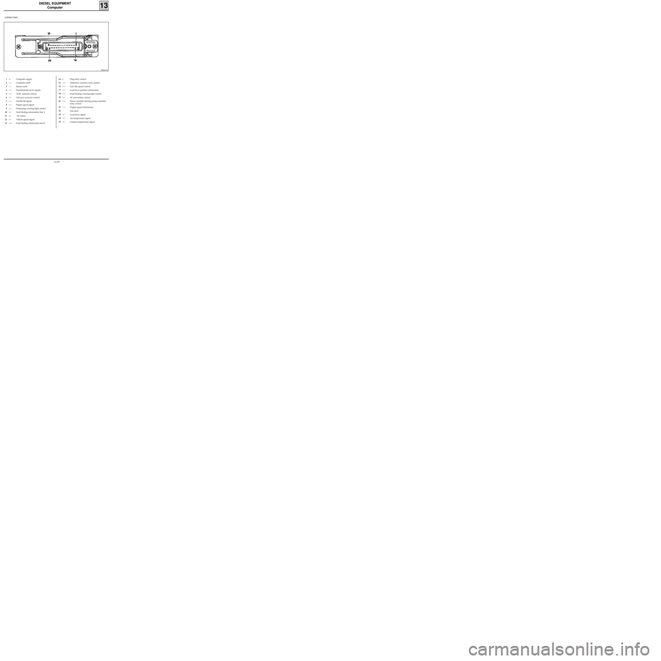
CONNECTION
1-<-
2-----
3-----
4-->-
5-->-
6-->-
7-<--
8-<--
9-->-
10-<--
11-<--
12-<--
13-><-Computer supply
Computer earth
Sensor earth
Potentiometer lever supply
EGR solenoid control
Advance corrector control
Needle lift signal
Engine speed signal
Preheating warning light control
Fault finding information line L
AC status
Vehicle speed signal
Fault finding information line KPlug relay control
Altimetric corrector relay control
Fast idle speed control
Load lever position information
Fault finding warning light control
AC prevention control
Power assisted steering pump assembly
relay control
Engine speed information
Not used
Load lever signal
Air temperature signal
Coolant temperature signal14-->-
15-->-
16-->-
17-->-
18-->-
19-->-
20 -->-
21-----
22
23-<--
24-<--
25-<--
13-37
Page 118 of 208
DIESEL EQUIPMENT
Defect modes
13
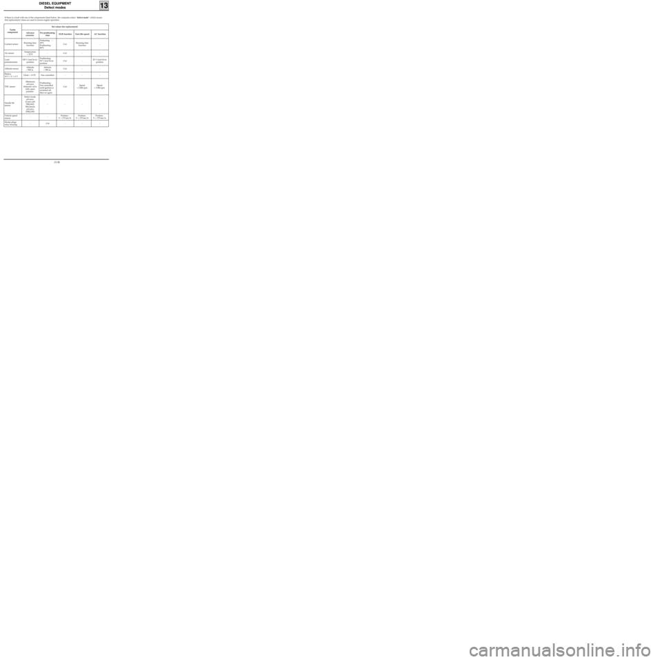
If there is a fault with one of the components listed below, the computer enters "defect mode", which means
that replacement values are used to ensure engine operation.
Faulty
componentSet values (for replacement)
Advance
corrector Pre-postheating
timeEGR function Fast idle speed AC function
Coolant sensorRunning time
functionPreheating : -
30°C
Postheating :
80°CCutRunning time
function-
Air sensorTemperature
= 22°C- Cut - -
Load
potentiometer100 % load lever
positionPostheating:
30 % load lever
position Cut - 20 % load lever
position
Altitude sensorAltitude
= 900 mAltitude
= 900 mCut - -
Battery
16 V < U < 6 VUbatt = 13.5V Not controlled - - -
TDC sensorMinimum
advance
Solenoid valve
fully open
position Postheating :
Not controlled
until ignition is
switched off
then on againCutSpeed
= 2 000 rpmSpeed
= 2 000 rpm
Needle lift
sensorDefect mode
advance
(Carto soft
F8Q 662)
Maximum
advance
(F8Q 630)----
Vehicle speed
sensor--Position :
V = 175 km/hPosition :
V = 175 km/hPosition :
V = 175 km/h
Heater plugs
relay housing- Cut - - -
13-38
Page 119 of 208
DIESEL EQUIPMENT
Pump
13
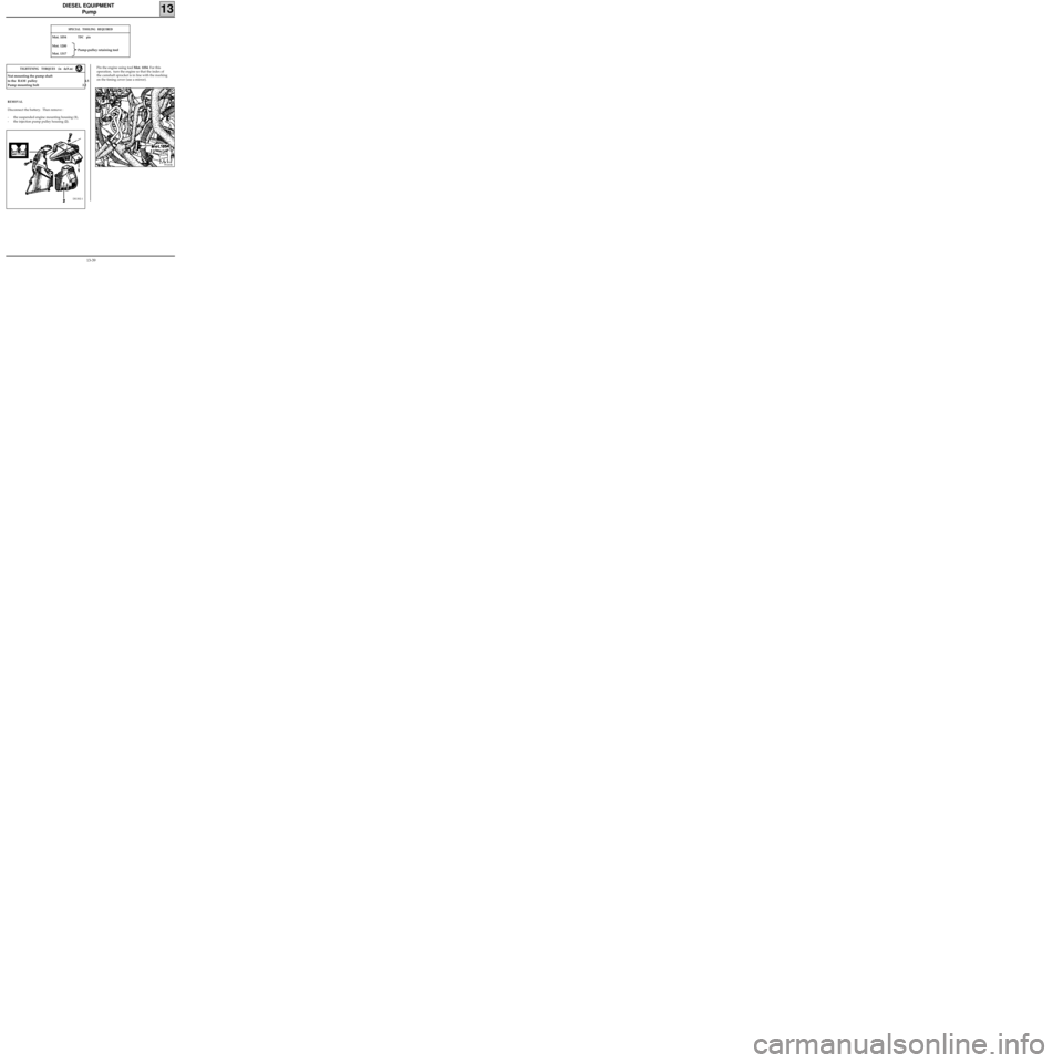
REMOVAL
Disconnect the battery. Then remove :
- the suspended engine mounting housing (1),
- the injection pump pulley housing (2).
DI1302-1
Pin the engine using tool Mot. 1054. For this
operation, turn the engine so that the index of
the camshaft sprocket is in line with the marking
on the timing cover (use a mirror).
SPECIAL TOOLING REQUIRED
Mot. 1054TDC pin
Mot. 1200
Pump-pulley retaining tool
Mot. 1317
99183R
Nut mounting the pump shaft
to the RAM pulley 4.5
Pump mounting bolt 2.2
TIGHTENING TORQUES (in daN.m)
13-39
Page 121 of 208
DIESEL EQUIPMENT
Pump - Timing
13
IMPORTANT : the engine must only be rotated by
turning a wheel, in 5th gear, and in its operating
direction; if it is accidentally turned in the
opposite direction, repeat the operations for
checking and adjusting the timing.
CHECKING THE SETTING OF INJECTION PUMPS
FITTED WITH RAM PULLEYS
Turn the engine twice in the operating direction
(moving one wheel and having engaged 5th
gear).
Remove the timing shaft plug situated on the
pump cover.
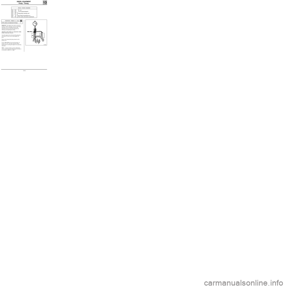
Fit tool Mot. 1079 and zero the dial gauge on
pump cam "rest" zone (this operation will be
made easier by turning the engine in its operating
direction).
NOTE : in order to obtain a precise adjustment,
and to avoid bringing the dial gauge to its limit, it
is advisable to adjust it to 1 mm.
SPECIAL TOOLING REQUIRED
Mot. 1054TDC pin
Mot. 1079 LUCAS pump timing kit
Mot. 1200
Mot. 1317
Mot. 135 Set of tools for operations on a
Mot. 1359 RAM pulley (micrometric adjustment)
91258R2
RAM pulley nut (adjustment locking) 9
TIGHTENING TORQUES (in daN.m)
Pump-pulley retaining tool
13-41
Page 122 of 208
DIESEL EQUIPMENT
Pump - Timing
13
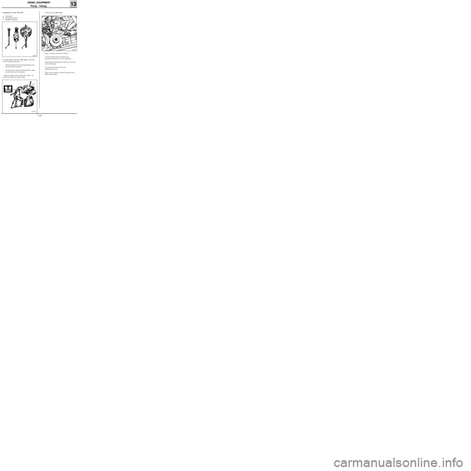
Components of tool Mot. 1079
A Timing pin
B Dial gauge support
C30 mm dial gauge
91285R
Lock the engine using tool Mot. 1054, according
to the following procedure :
- Turn the engine in its operating direction (clo-
ckwise from timing end).
- Locate the spot on the camshaft pulley where
the reference mark will appear .
- Stop the engine from turning half a tooth be-
fore the two reference marks align.
DI1303-1
- Fit the pin, tool Mot. 1054.
12419R
- Keep a constant pressure on the pin.
- Turn the engine slowly until the pin
penetrates into the slot in the crankshaft .
- Check the pump piston lift, which may be read
on the dial gauge.
- The value is marked on the load
potentiometer lever.
- If the value is incorrect, adjust the timing (see
following method).
13-42
Page 124 of 208
DIESEL EQUIPMENT
Pump - Timing
13
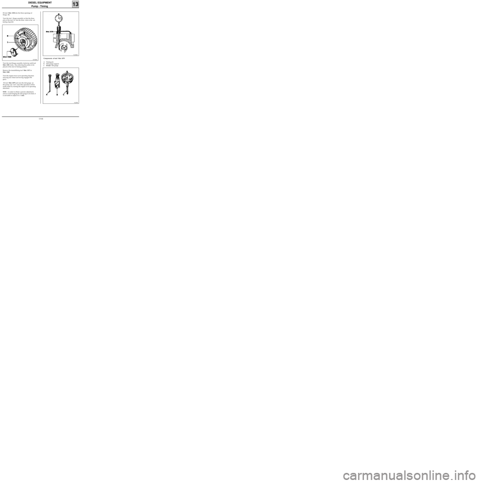
Fit tool Mot. 1358 into the three openings of
flange (B).
Turn the tool - flange assembly so that the three
pins of the tool fit into the three slots in the ad-
justing ring bolt.
12312R2
Turn the tool-flange assembly clockwise until tool
Mot. 1358 locks, thus allowing the pulley to be
placed at the start of timing position .
Remove the immobilising tool Mot. 1317 or
Mot. 1200.
Turn the engine twice in its operating direction
(moving one wheel and having engaged 5th
gear).
Fit tool Mot. 1079 and zero the dial gauge on
the pump cam "rest" zone (this operation will be
made easier by turning the engine in its operating
direction).
NOTE : in order to obtain a precise adjustment,
and to avoid bringing the dial gauge to its limit, it
is advisable to adjust it to 1 mm.
91258R2
Components of tool Mot. 1079
A Timing pin
B Dial gauge support
C30 mm dial gauge
91285R
13-44
Page 125 of 208
DIESEL EQUIPMENT
Pump - Timing
13
DI1303-1
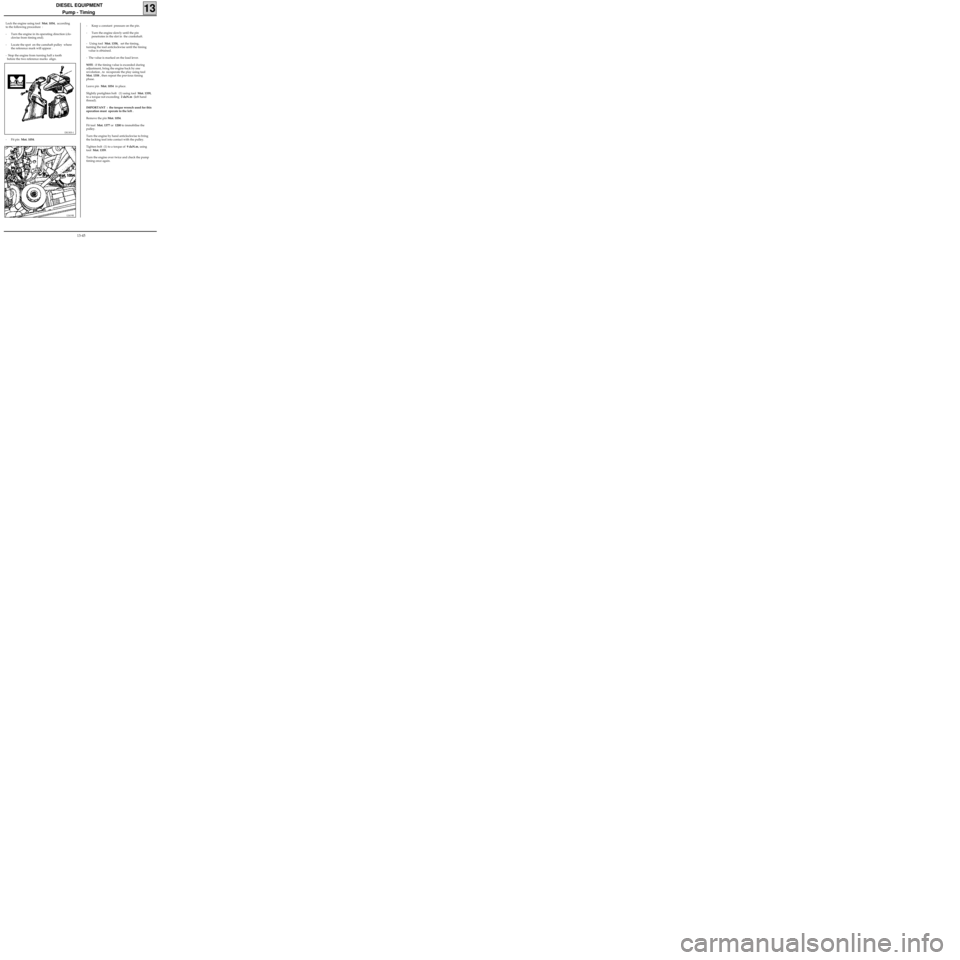
- Fit pin Mot. 1054.
12419R
- Keep a constant pressure on the pin.
- Turn the engine slowly until the pin
penetrates in the slot in the crankshaft.
- Using tool Mot. 1358, set the timing,
turning the tool anticlockwise until the timing
value is obtained.
- The value is marked on the load lever.
NOTE : if the timing value is exceeded during
adjustment, bring the engine back by one
revolution , to recuperate the play using tool
Mot. 1358 , then repeat the previous timing
phase.
Leave pin Mot. 1054 in place.
Slightly pretighten bolt (1) using tool Mot. 1359,
to a torque not exceeding 2 daN.m (left hand
thread).
IMPORTANT : the torque wrench used for this
operation must operate to the left .
Remove the pin Mot. 1054.
Fit tool Mot. 1377 or 1200 to immobilise the
pulley.
Turn the engine by hand anticlockwise to bring
the locking tool into contact with the pulley.
Tighten bolt (1) to a torque of 9 daN.m, using
tool Mot. 1359.
Turn the engine over twice and check the pump
timing once again.
Lock the engine using tool Mot. 1054, according
to the following procedure :
- Turn the engine in its operating direction (clo-
ckwise from timing end).
- Locate the spot on the camshaft pulley where
the reference mark will appear .
- Stop the engine from turning half a tooth
before the two reference marks align.
13-45
Page 126 of 208
DIESEL EQUIPMENT
Adjusting idle speed
13
12870R
It is vital to make these adjustments when the en-
gine is warm, and after the engine cooling fan
has operated at least twice.
The idle speed adjustment and anti-stalling
function adjustment must be carried out
correctly, since these operations directly
influence the behaviour of the engine at idle
speed and in the deceleration phase (hesitation
idle speed lasts too long, etc.).
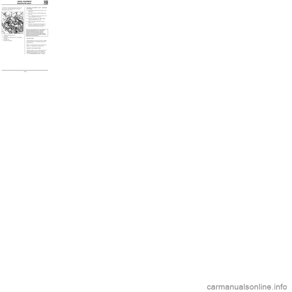
1 Idle speed adjustment screw
2 Load lever
3 Residual flow adjustment screw (anti-stalling
function)
4 Fast idle lever
5 Idle speed cable grip
FAST IDLE SPEED
Without applying a vacuum to the LDA, position
the cable grip (5) at 2 ± 1 mm from the fast idle
speed lever (4).
NOTE : the fast idle speed value is not directly ad-
justable; it is adjusted on the injection unit.
CHECKING THE MAXIMUM SPEED
Whilst the engine is warm, accelerate to full load ;
the engine speed must be between 4 500 and
4 700 rpm (this adjustment can only be carried
out in a Renault Injection Centre workshop).
IDLE SPEED AND RESIDUAL FLOW ADJUSTMENT
(anti-stalling)
a)Ensure that the fast idle speed function is not
operational .
b)Adjust the idle speed to 825 ± 25 rpm. using
screw (1).
c)Place a 4 mm shim between the load lever (2)
and the residual flow screw (3).
d)Adjust the engine speed to 1 250 ± 50 rpm.
using the residual flow screw (3).
e)Remove the 4 mm shim then accelerate
sharply twice.
f)Check the conformity of the idle speed; if
necessary, repeat the idle speed adjustment
and check the residual flow once more.
13-46