RENAULT KANGOO 1997 KC / 1.G Engine And Peripherals Workshop Manual
KANGOO 1997 KC / 1.G
RENAULT
RENAULT
https://www.carmanualsonline.info/img/7/1731/w960_1731-0.png
RENAULT KANGOO 1997 KC / 1.G Engine And Peripherals Workshop Manual
Page 127 of 208
93703S
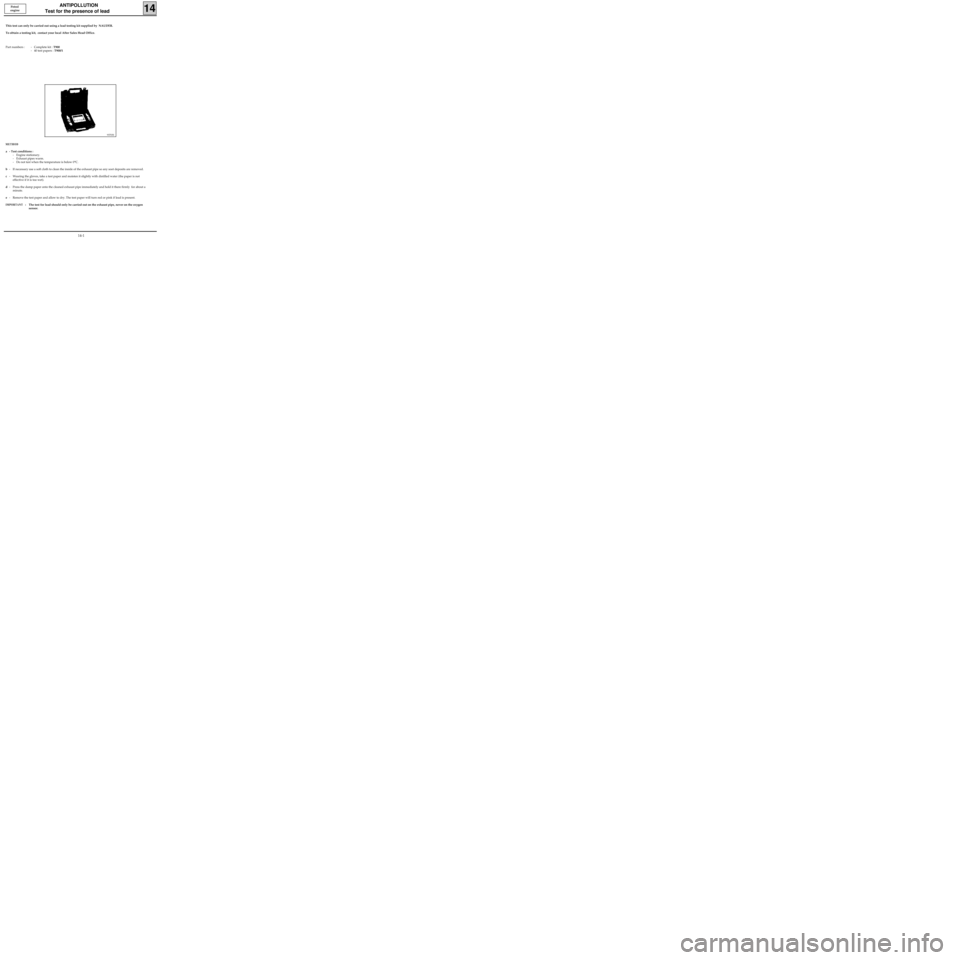
This test can only be carried out using a lead testing kit supplied by NAUDER.
To obtain a testing kit, contact your local After Sales Head Office.
Part numbers : - Complete kit : T900
- 40 test papers : T900/1
ANTIPOLLUTION
Test for the presence of lead
14
METHOD
a - Test conditions :
- Engine stationary.
- Exhaust pipes warm.
- Do not test when the temperature is below 0°C.
b- If necessary use a soft cloth to clean the inside of the exhaust pipe so any soot deposits are removed.
c- Wearing the gloves, take a test paper and moisten it slightly with distilled water (the paper is not
effective if it is too wet).
d- Press the damp paper onto the cleaned exhaust pipe immediately and hold it there firmly for about a
minute.
e- Remove the test paper and allow to dry. The test paper will turn red or pink if lead is present.
IMPORTANT: The test for lead should only be carried out on the exhaust pipe, never on the oxygen
sensor.
Petrol
engine
14-1
Page 128 of 208
ANTIPOLLUTION
Fuel vapour rebreathing
14
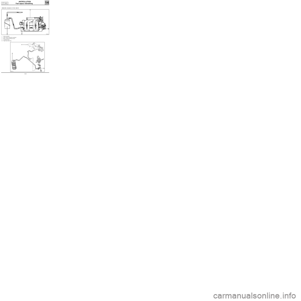
OPERATING DIAGRAM OF THE CIRCUIT
1 Inlet manifold
2 Fuel vapour absorber (canister)
3 RCO control solenoid valve
4 Cylinder head
R Pipe from fuel tank
99933R
PRC14.1
D7F Engine
14-2
Page 129 of 208
ANTIPOLLUTION
Fuel vapour rebreathing
14E7J Engine
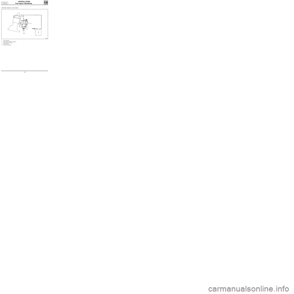
OPERATING DIAGRAM OF THE CIRCUIT
1 Inlet manifold
2 Fuel vapour absorber (canister)
3 RCO control solenoid
4 Throttle body
R Pipe from fuel tank
13123R
14-3
Page 130 of 208
ANTIPOLLUTION
Fuel vapour rebreathing
14
CONDITION FOR BLEEDING THE CANISTER ( D7F
engine)
• Coolant temperature greater than+ 15 °C
•Air temperature greater than +10 °C.
• No load position not recognised (if there is a
fault in the throttle potentiometer sensor, the
condition of no load position not recognised is
replaced by an engine speed condition
R > 1500 rpm.).
It is possible to visualise the cyclical opening ratio
for the canister bleed solenoid using the
XR25
and #23. The solenoid is closed if #23 = 0.7 %
CONDITION FOR BLEEDING THE CANISTER (E7J
engine)
During richness regulation
Coolant temperature greater than 50°C.
Air temperature greater than 15°C.
No load position not recognised (if there is a fault
in the throttle potentiometer sensor, the
condition of no load position not recognised is
replaced by an engine speed condition
R > 1500 rpm.).
Outside richness regulation
•Coolant temperature greater than 50°C.
•Air temperature greater than 15°C.
•Full load position recognised (function of
engine speed and manifold pressure).
If there is a fault in the oxygen sensor, bleeding is
permitted outside of no load conditions.
It is possible to visualise the cyclical opening ratio
for the canister bleed solenoid using the
XR25
and #23. The solenoid is closed if #23 = 0.7 %
(minimum value).
14-4
Page 131 of 208
ANTIPOLLUTION
Fuel vapour rebreathing
14
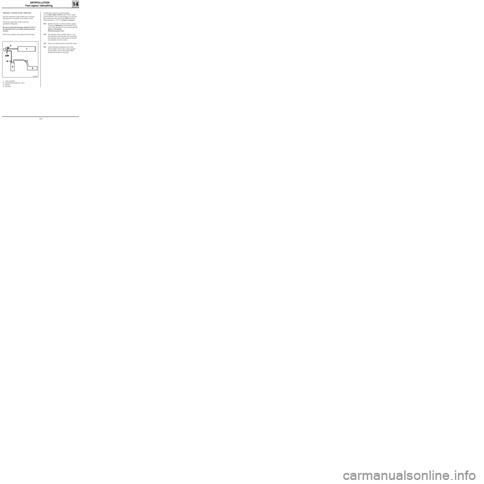
CHECKING CANISTER BLEED OPERATION
Incorrect operation of the system may cause the
idle speed to be unstable or the engine to stall.
Check the conformity of the circuit (see
operational diagrams)
Be sure to check that the pipe marked "CAN" on
the solenoid valve is correctly connected to the
canister.
Check the condition of the pipes to the fuel tank.
97393R6
1Inlet manifold
2Canister bleed solenoid valve
3Canister
4Fuel tankAt idle speed connect a pressure gauge
(- 3 ; +3 bars) (Mot. 1311-01) to the "CAN" outlet
on the solenoid valve, to check there is no vacuum
(the command value read by the
XR25 for #23 re-
mains minimal X = 0.7 % ). Is there a vacuum ?
YESIgnition off, use a vacuum pump to apply a
vacuum of 500 mbars to the solenoid valve
at (C). This should not vary by more than 10
mbars in 30 seconds.
Does the pressure vary?
YESThe solenoid valve is faulty. Renew it. Air
must be blown into the pipe (A) connecting
the solenoid valve to the canister to remove
any particles of active carbon.
NOThere is an electrical fault. Check the circuit.
NOUnder bleeding conditions (not at idle
speed, engine warm), the vacuum should
increase (the value for #23 on the XR25
should also be seen to increase).
14-5
Page 132 of 208
ANTIPOLLUTION
Fuel vapour rebreathing
14
LOCATION-REMOVAL OF COMPONENTS
CANISTER BLEED SOLENOID VALVE
(1)
E7J Engine
It is mounted above the inlet manifold,
underneath the cover
D7F Engine
It is mounted at the front, on the lifting bracket.
13242R2
99939-1R3
REMOVAL OF THE FUEL VAPOUR ABSORBER (1)
This is located in the front right hand wheel arch.
REMOVAL
Disconnect the pipe connecting the canister to the
inlet manifold, from the top of the vehicle.
From the bottom, remove the wheel arch .
Disconnect the pipe at (2) connecting the
canister to the fuel tank.
Remove the three bolts at (3) mounting the
canister (1) then extract it.
13049R
14-6
Page 133 of 208
ANTIPOLLUTION
Oil vapour rebreathing
14
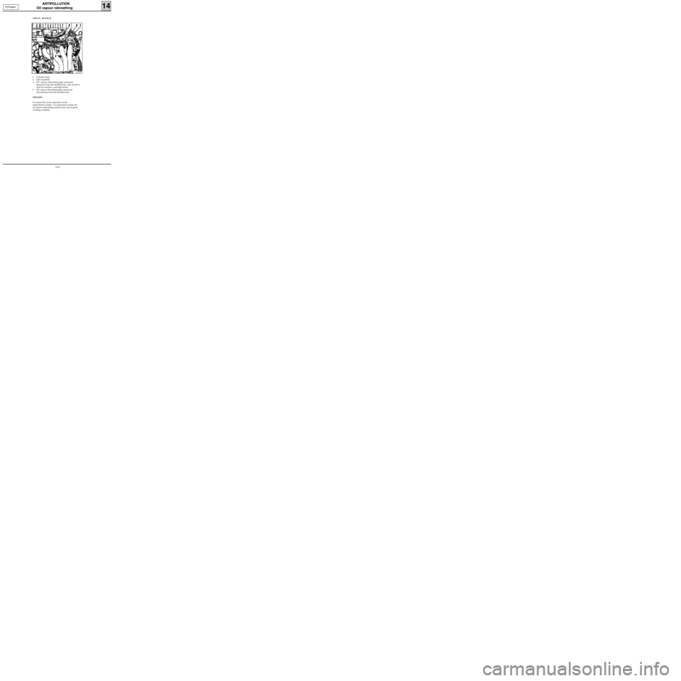
CIRCUIT DIAGRAM
1 Cylinder head cover
2 Inlet manifold
3 Oil vapour rebreathing pipe connected upstream from the throttle body (the circuit is used
for medium and high loads)
4 Oil vapour rebreathing pipe connected downstream from the throttle body
5 Air pipe
6 Throttle body
99932R
D7F Engine
14-7
Page 134 of 208
ANTIPOLLUTION
Oil vapour rebreathing
14
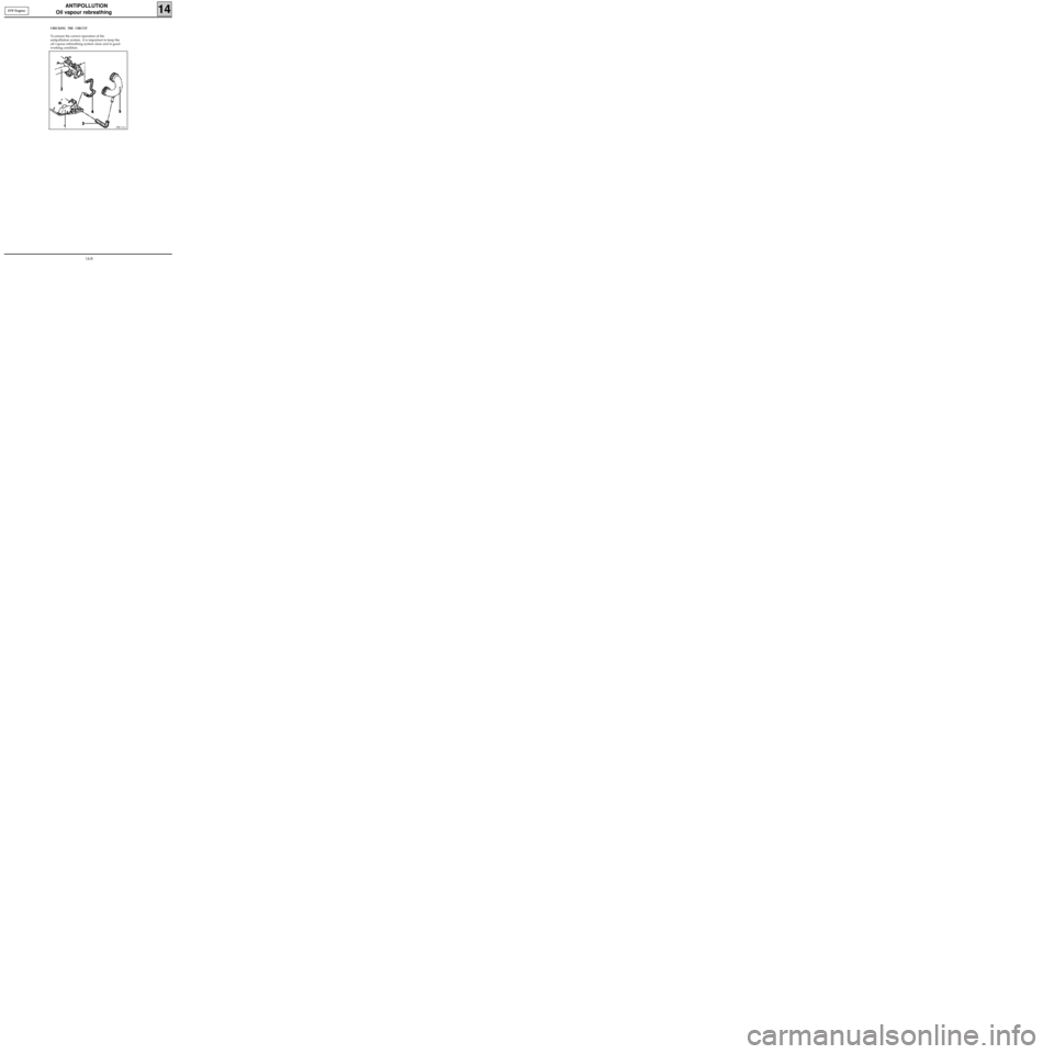
CHECKING THE CIRCUIT
To ensure the correct operation of the
antipollution system, it is important to keep the
oil vapour rebreathing system clean and in good
working condition.
PRC14.2
D7F Engine
14-8
Page 135 of 208
ANTIPOLLUTION
Oil vapour rebreathing
14E7J Engine
CIRCUIT DIAGRAM
1 Cylinder head
2 Inlet manifold
3 Oil vapour rebreathing pipe connected
upstream from the throttle body (the circuit is
used for medium and high loads)
4 Oil vapour rebreathing pipe connected
downstream from the throttle body
CHECKING
To ensure the correct operation of the
antipollution system, it is important to keep the
oil vapour rebreathing system clean and in good
working condition.
13335R
14-9
Page 136 of 208
ANTIPOLLUTION
Oil vapour rebreathing
14
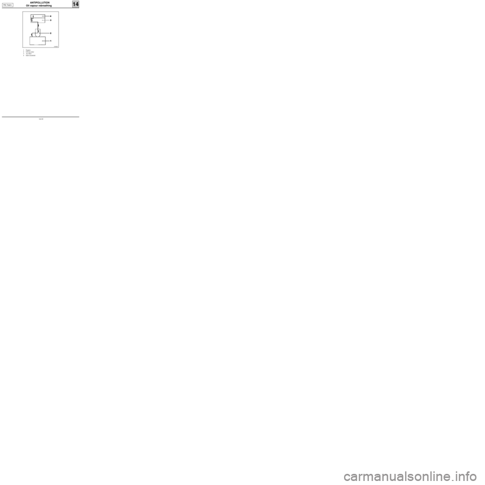
1 Engine
2 Oil decanter
3 Air filter
4 Inlet manifold
13042R
F8Q Engine
14-10
