RENAULT KANGOO 1997 KC / 1.G Engine And Peripherals Manual PDF
KANGOO 1997 KC / 1.G
RENAULT
RENAULT
https://www.carmanualsonline.info/img/7/1731/w960_1731-0.png
RENAULT KANGOO 1997 KC / 1.G Engine And Peripherals Manual PDF
Page 72 of 208
FUEL MIXTURE
Throttle body
12D7F engine
Throttle body mounting bolt on
inlet manifold 1
Throttle body stiffening bracket
mounting bolt on cylinder head 1
TIGHTENING TORQUES (in daN.m)
There are no special notes for removal - refitting.
12-7
Page 73 of 208
FUEL MIXTURE
Throttle body
12
Throttle body mounting bolt 1
TIGHTENING TORQUES (in daN.m)
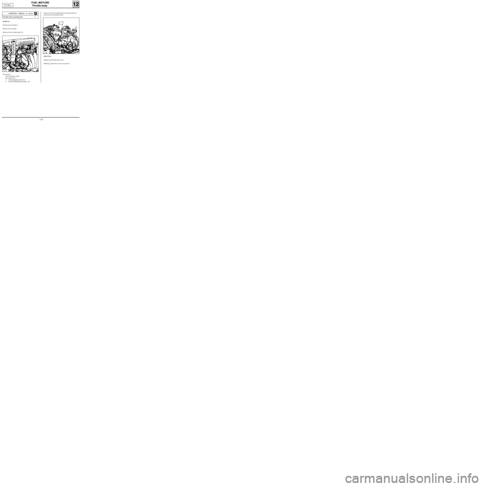
REMOVAL
Disconnect the battery.
Remove the air filter.
Remove the air intake pipe (1).
Disconnect:
- the accelerator cable,
- the connectors :
• of the stepping motor (2),
• of the throttle potentiometer (3).
E7J engine
Remove the four throttle body mounting bolts (5)
and remove the throttle body.
REFITTING
Replace the throttle body seal.
Refitting is then the reverse of removal.
13339R113338R
12-8
Page 74 of 208
FUEL MIXTURE
Inlet manifold
12D7F engine
TIGHTENING TORQUES (in daN.m)
There are no special notes for removal - refitting
TIGHTENING TORQUES (in daN.m)
Injector gallery mounting bolt on manifold 1
Manifold mounting nut on cylinder head 1.7
Manifold mounting stud on cylinder head 1
12-9
Page 75 of 208
FUEL MIXTURE
Inlet manifold
12
Inlet manifold bolt and nut 2
TIGHTENING TORQUES (in daN.m)
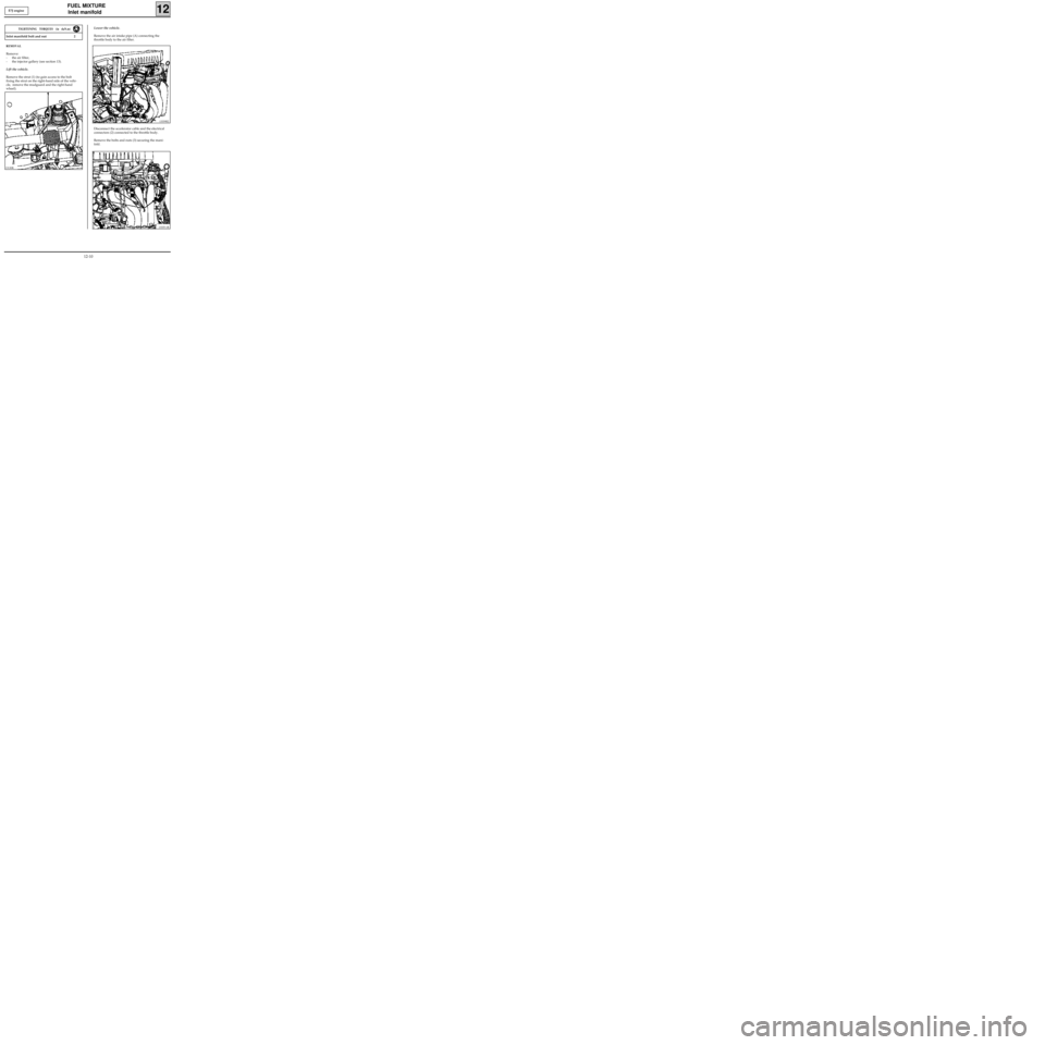
REMOVAL
Remove:
- the air filter,
- the injector gallery (see section 13).
Lift the vehicle.
Remove the strut (1) (to gain access to the bolt
fixing the strut on the right-hand side of the vehi-
cle, remove the mudguard and the right-hand
wheel).
E7J engine
13339R2
Disconnect the accelerator cable and the electrical
connectors (2) connected to the throttle body.
Remove the bolts and nuts (3) securing the mani-
fold. Lower the vehicle.
Remove the air intake pipe (A) connecting the
throttle body to the air filter.
13335-1R
13130R
12-10
Page 76 of 208
FUEL MIXTURE
Inlet manifold
12
Remove the two bolts (4) mounting the retaining
bracket on the cylinder block. E7J engine
13338R1
Extract the manifold.
REFITTING
Replace the inlet manifold gaskets.
Refitting is then the reverse of removal.
12-11
Page 77 of 208
FUEL MIXTURE
Exhaust manifold
12D7F engine
Manifold mounting nut 2.5
Manifold mounting stud 1
Exhaust downpipe mounting bolt 2.2
TIGHTENING TORQUES (in daN.m)
There are no special notes for the removal - refitting.
12-12
Page 78 of 208
FUEL MIXTURE
Exhaust manifold
12
Manifold mounting bolt 2
TIGHTENING TORQUES (in daN.m)
REMOVAL
Remove the multifunction support (1) (see section
10).
Disconnect the exhaust manifold / exhaust link
(2).
Remove the heat shield (3).
Remove the exhaust manifold. E7J engine
13239R2
REFITTING
Replace the manifold gasket.
Refitting is then the reverse of removal.
12-13
Page 79 of 208
FUEL MIXTURE
Inlet/Exhaust manifolds
12F8Q engine
Manifold mounting studs on cylinder head 1
Manifold mounting nuts on cylinder head 2.7
Inlet manifold strut mounting bolt 2.5
Cylinder block strut mounting bolt 2.5
TIGHTENING TORQUES (in daN.m)
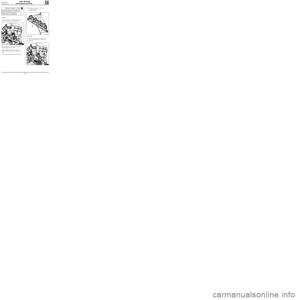
REMOVAL
Remove the air filter (two mounting bolts at the
top, two mounting nuts at the bottom (1)).
Remove, from above, the two nuts fixing the ex-
haust downpipe to the manifold.
Slacken, without removing it, the nut on the
clamp connecting the downpipe to the exhaust
pipe.
Tilt the exhaust downpipe towards the gearbox.
Remove the nuts securing the manifolds:
- nuts (A) from above,
- nuts (B) from below.
PRO12.1
Special note
To remove nut (C) located above the starter mo-
tor, use a small ratchet (6.35 mm square) and a
universal joint.
13047-1R1
13047R
12-14
Page 80 of 208
FUEL MIXTURE
Inlet/exhaust manifolds
12F8Q engine
REFITTING
Replace the manifold gaskets (metal part of the
gasket on the manifold side).
Replace the gaskets between the inlet manifold
and the air filter.
Replace the steel gasket between the exhaust ma-
nifold and the exhaust downpipe.
For the other operations, refitting is the reverse of
removal.
12-15
Page 81 of 208
FUEL SUPPLY
Fuel cut off in case of an impact
13
OBJECTIVE
The main function of this feature is to avoid any
fires that may result from the leakage of fuel du-
ring an accident. In order to achieve this, all
components pumping fuel from the fuel tank will
automatically stop functioning during and imme-
diately after the impact. They can then only be
made to operate again by a mechanical action car-
ried out by the driver or the repairer.
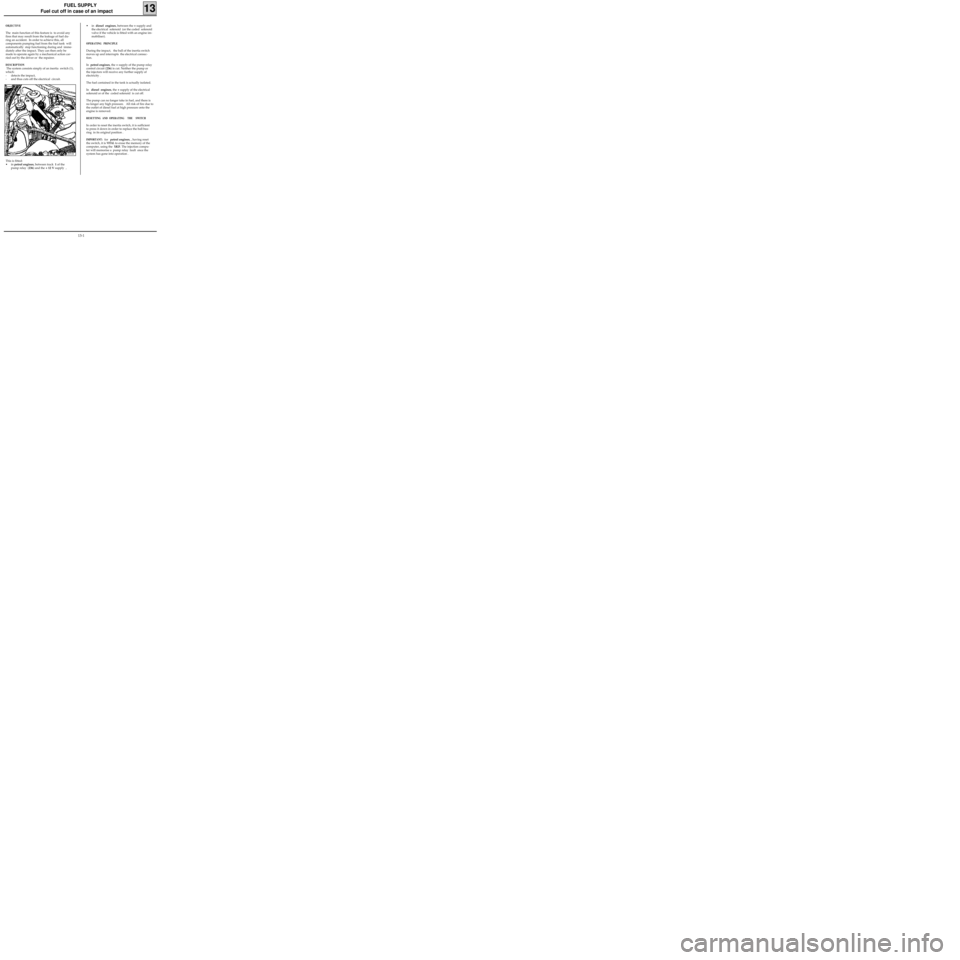
DESCRIPTION
The system consists simply of an inertia switch (1),
which:
- detects the impact,
- and thus cuts off the electrical circuit.
13051R
This is fitted:
• in petrol engines, between track 1 of the
pump relay (236) and the + 12 V supply ,
• in diesel engines, between the + supply and
the electrical solenoid (or the coded solenoid
valve if the vehicle is fitted with an engine im-
mobiliser).
OPERATING PRINCIPLE
During the impact, the ball of the inertia switch
moves up and interrupts the electrical connec-
tion.
In petrol engines, the + supply of the pump relay
control circuit (236) is cut. Neither the pump or
the injectors will receive any further supply of
electricity .
The fuel contained in the tank is actually isolated.
In diesel engines, the + supply of the electrical
solenoid or of the coded solenoid is cut off.
The pump can no longer take in fuel, and there is
no longer any high pressure. All risk of fire due to
the outlet of diesel fuel at high pressure onto the
engine is removed.
RESETTING AND OPERATING THE SWITCH
In order to reset the inertia switch, it is sufficient
to press it down in order to replace the ball bea-
ring in its original position .
IMPORTANT: for petrol engines, , having reset
the switch, it is
VITAL to erase the memory of the
computer, using the
XR25. The injection compu-
ter will memorise a pump relay fault once the
system has gone into operation .
13-1
