sensor RENAULT KANGOO 1997 KC / 1.G Foult Finding - Injection Owner's Manual
[x] Cancel search | Manufacturer: RENAULT, Model Year: 1997, Model line: KANGOO, Model: RENAULT KANGOO 1997 KC / 1.GPages: 363
Page 86 of 363
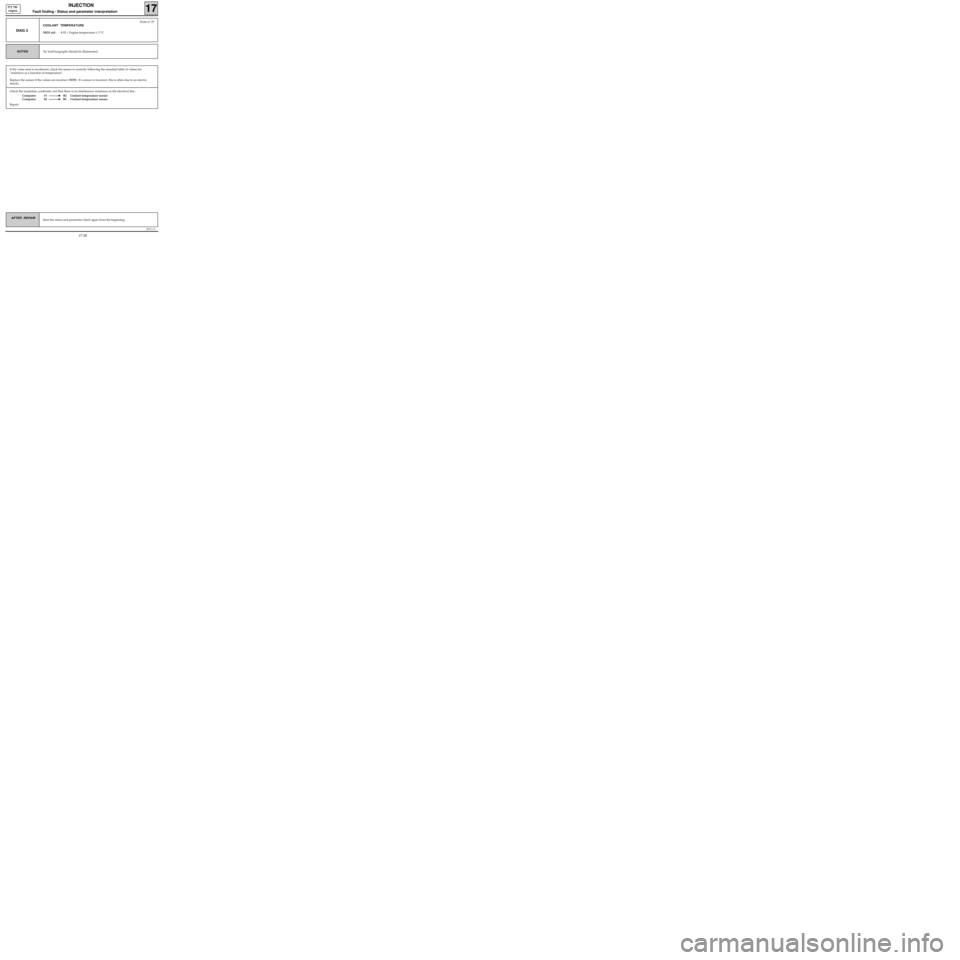
Check the insulation, continuity and that there is no interference resistance on the electrical line :
Computer 15 B2 Coolant temperature sensor
Computer 44 B1 Coolant temperature sensor
Repair.
JF5111.0
INJECTION
Fault finding - Status and parameter interpretation17
E7J 780
engine
AFTER REPAIRStart the status and parameter check again from the beginning.
DIAG 3
Fiche n° 27
COOLANT TEMPERATURE
XR25 aid: # 02 = Engine temperature ± 5 °C
No fault bargraphs should be illuminated.NOTES
If the value read is incoherent, check the sensor is correctly following the standard table of values for
"resistance as a function of temperature".
Replace the sensor if the values are incorrect (
NOTE : If a sensor is incorrect, this is often due to an electric
shock).
17-38
Page 87 of 363
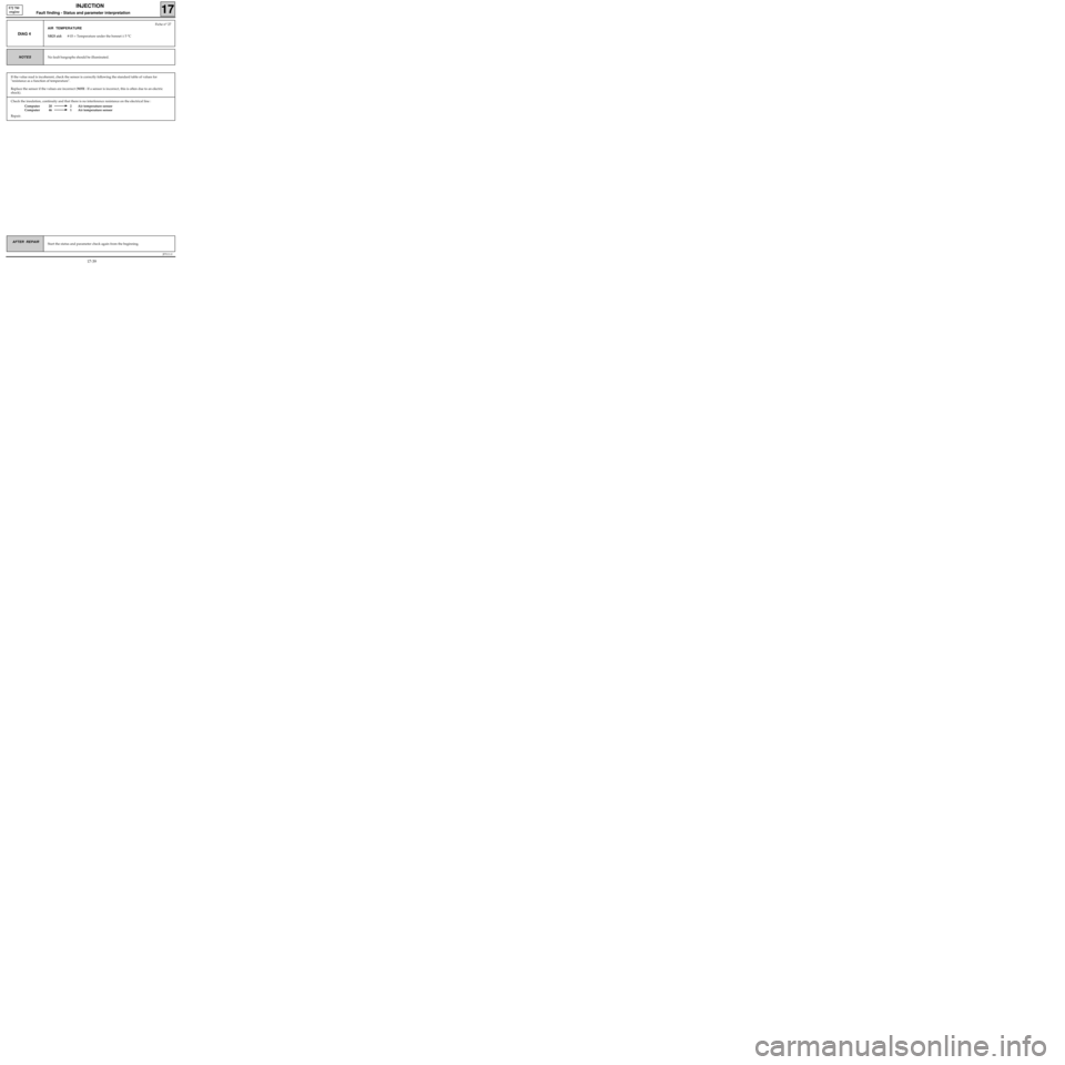
Check the insulation, continuity and that there is no interference resistance on the electrical line :
Computer 20 2 Air temperature sensor
Computer 46 1 Air temperature sensor
Repair.
JF5111.0
INJECTION
Fault finding - Status and parameter interpretation17
E7J 780
engine
AFTER REPAIRStart the status and parameter check again from the beginning.
DIAG 4
Fiche n° 27
AIR TEMPERATURE
XR25 aid:# 03 = Temperature under the bonnet ± 5 °C
No fault bargraphs should be illuminated.NOTES
If the value read is incoherent, check the sensor is correctly following the standard table of values for
"resistance as a function of temperature".
Replace the sensor if the values are incorrect (
NOTE : If a sensor is incorrect, this is often due to an electric
shock).
17-39
Page 88 of 363
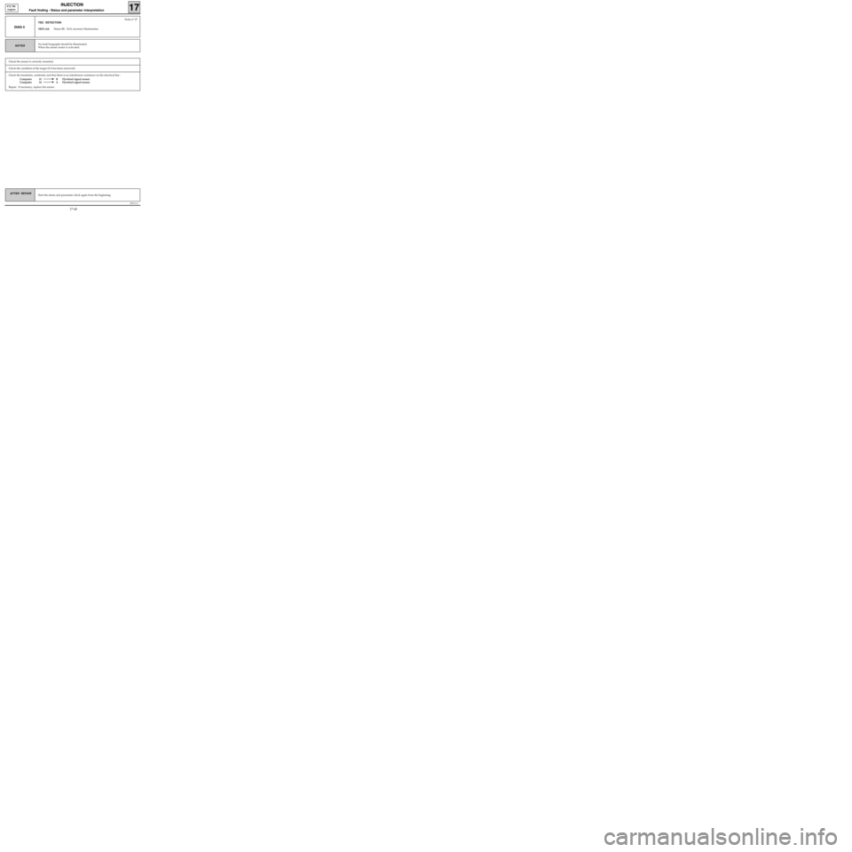
Check the insulation, continuity and that there is no interference resistance on the electrical line :
Computer 33 B Flywheel signal sensor
Computer 34 A Flywheel signal sensor
Repair. If necessary, replace the sensor.
JF5111.0
INJECTION
Fault finding - Status and parameter interpretation17
E7J 780
engine
AFTER REPAIRStart the status and parameter check again from the beginning.
DIAG 5
Fiche n° 27
TDC DETECTION
XR25 aid:Status BG 3LH, incorrect illumination
No fault bargraphs should be illuminated.
When the starter motor is activated.NOTES
Check the sensor is correctly mounted.
Check the condition of the target (if it has been removed).
17-40
Page 89 of 363
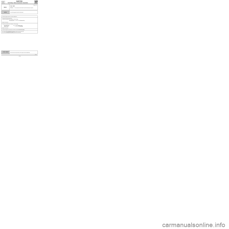
Check the insulation and continuity of the wiring:
Fuel pump relay L5 Impact sensor
Impact sensor C1 Fuel pump
Repair if necessary.
Check the 30A fuel pump fuse.
Check the insulation and continuity of the wiring:
Fuel pump fuse L3 Fuel pump relay
Repair if necessary.
JF5111.0
INJECTION
Fault finding - Status and parameter interpretation17
E7J 780
engine
AFTER REPAIRStart the status and parameter check again from the beginning.
DIAG 6
Fiche n° 27
FUEL PUMP
XR25 aid:The command mode should cause the fuel pump to operate
No fault bargraphs should be illuminated.NOTES
Check the hygiene and presence of earth on track C2 of the fuel pump.
If + 12 V is not reaching the fuel pump, replace the fuel pump relay.
If + 12 V is reaching the fuel pump, replace the fuel pump.
Check the impact sensor is correctly clipped in.
17-41
Page 91 of 363
The pinking sensor should give a signal which is variable and not zero, to prove that it is recording the
mechanical vibrations of the engine.
If the signal is zero:
- Check the sensor is correctly screwed in.
- Check the insulation and continuity of the wiring:
Computer 8 2 Pinking sensor
Computer 44 1 Pinking sensor
Computer 2 Pinking sensor screening
If necessary, replace the sensor.
JF5111.0
INJECTION
Fault finding - Status and parameter interpretation17
E7J 780
engine
AFTER REPAIRStart the status and parameter check again from the beginning.
DIAG 8
Fiche n° 27
ANTI-PINKING CIRCUIT
XR25 aid:# 13 is not zero and variable for fast idle or under load
No fault bargraphs should be illuminated.NOTES
17-43
Page 92 of 363
Check the insulation, continuity and that there is no interference resistance
on the line:
Computer 45 C Pressure sensor
Computer 44 A Pressure sensor
Computer 16 B Pressure sensor
Repair if necessary.
JF5111.0
INJECTION
Fault finding - Status and parameter interpretation17
E7J 780
engine
AFTER REPAIRStart the status and parameter check again from the beginning.
DIAG 9
Fiche n° 27
PRESSURE CIRCUIT
XR25 aid:Ignition on # 01 not coherent
At idle speed # 01 < Minimum or # 01 > Maximum
# 16 not coherent
No fault bargraphs should be illuminated.NOTES
# 01 not coherent
ignition on
# 01 < Minimum at idle
speed
# 16 not coherent
If all these points are correct, replace the sensor.
A vacuum pump with a pressure gauge may be used to check coherence with
# 01 and to show a faulty sensor.
# 01 > Maximum at idle
speedThe manifold pressure is often a sign of incorrect engine operation. Check
- the sealing of the pipe between the manifold and the sensor,
- the valve clearances,
- the canister bleed valve which should be closed at idle speed,
- cylinder compression using the OPTIMA 5800 station.
If all these points are correct, replace the sensor.
A vacuum pump with a pressure gauge may be used to check coherence with
# 01 and to show a faulty sensor.
17-44
Page 93 of 363
Connect the bornier in place of the computer and check the insulation and continuity of the line:
Computer 17 C Oxygen sensor
Repair if necessary.
JF5111.0
INJECTION
Fault finding - Status and parameter interpretation17
E7J 780
engine
AFTER REPAIRStart the status and parameter check again from the beginning.
DIAG 10
Fiche n° 27
RICHNESS REGULATION
XR25 aid:Richness regulation faulty
No fault bargraphs should be illuminated.
Ignition correct (a check may be made using the OPTIMA 5800 station).
No other status bargraph should show a fault.
NOTES
Check the sealing of the canister bleed valve (a leak can disrupt the richness considerably).
Check the sealing of the exhaust pipe upstream from the oxygen sensor.
Check the sealing of the inlet manifold.
If the vehicle has only been driven in town, the sensor is contaminated (try driving under load).
Check the fuel pressure.
If the idle speed is unstable, check the valve clearances.
Check the injectors (flow and shape of the jet).
If necessary, replace the oxygen sensor.
Check the connection and condition of the oxygen sensor connector.
Ignition on, during the timed phase, check for:
- earth on track B of the oxygen sensor.
-+ 12 V after the fuel pump relay on track A of the oxygen sensor.
Repair if necessary.
17-45
Page 96 of 363
if the value read is incoherent:
- Check that the sensor is correctly mounted and supplied:
•+12 V on A1
• Earth on B2
- Check the insulation, continuity and that there is no interference resistance on the line:
Computer 12 B1 vehicle speed sensor
NOTE : Check the different functions that use this information.
Repair.
JF5111.0
INJECTION
Fault finding - Status and parameter interpretation17
E7J 780
engine
AFTER REPAIRStart the status and parameter check again from the beginning.
DIAG 13
Fiche n° 27
VEHICLE SPEED
XR25 aid:# 18 = Speed read on speedometer in km/h
No fault bargraphs should be illuminated.
Check on a road test.NOTES
The fault persists! Replace the speed sensor.
17-48
Page 98 of 363

JF5111.0
INJECTION
Fault finding - Status and parameter interpretation17
E7J 780
engine
AFTER REPAIRStart the status and parameter check again from the beginning.
NOTES
DIAG 15
Fiche n° 27
EMISSION OF POLLUTANTS
XR25 aid:None
No fault bargraphs should be illuminated.NOTES
0.97 ≤ λ ≤ 1.03
at 2500 rpm.The oxygen sensor loops correctly at 2500 rpm.
If CO > 0.3 % at 2500 rpm.
NOTES 0.97 ≤ λ ≤ 1.03
at 2500 rpm.The oxygen sensor does not loop correctly at 2500 rpm.
There is a fault with the injection or the sensor.
The catalytic converter is faulty.
NOTE : it is vital to determine the cause of the catalytic converter damage to
avoid a new converter also being damaged.
If λ < 0.97 or λ > 1.03 at idle speed
Check the sensor earth and heating.
Check there is no air leak at the manifold.
17-50
Page 99 of 363
JF5111.0
INJECTION
Fault finding - Status and parameter interpretation17
E7J 780
engine
AFTER REPAIRStart the status and parameter check again from the beginning.
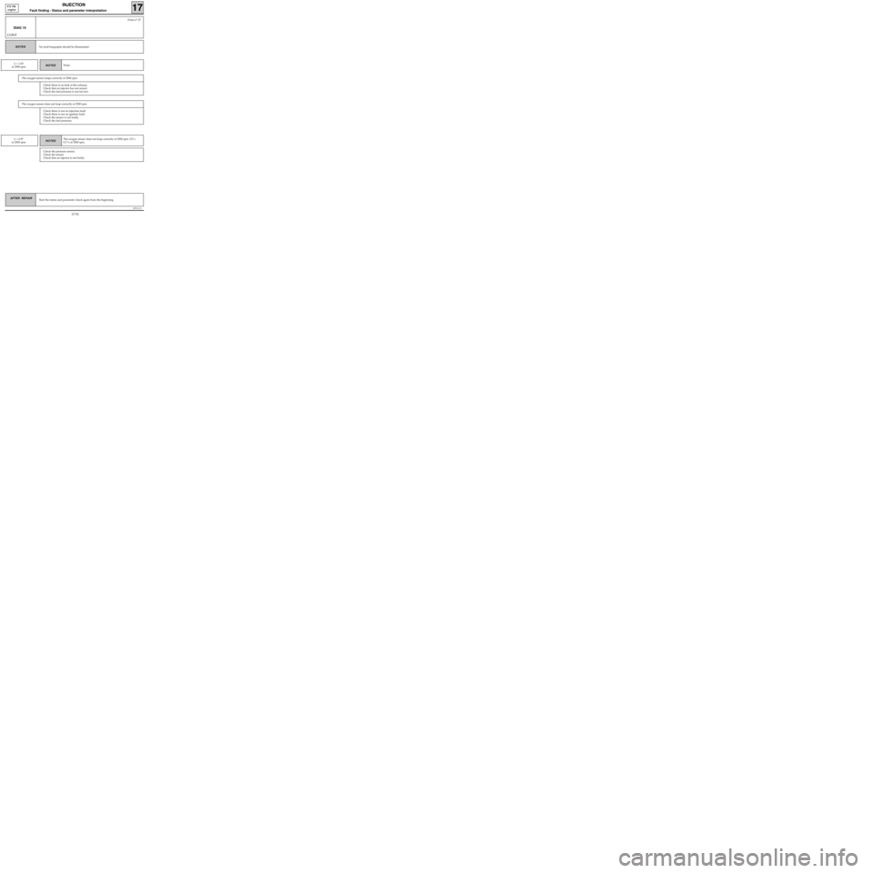
DIAG 15
CONT
Fiche n° 27
No fault bargraphs should be illuminated.NOTES
NOTES λ > 1.03
at 2500 rpm.None
The oxygen sensor loops correctly at 2500 rpm.
NOTES λ < 0.97
at 2500 rpm.The oxygen sensor does not loop correctly at 2500 rpm. CO >
0.3 % at 2500 rpm.
Check the pressure sensor.
Check the sensor.
Check that an injector is not faulty.
Check there is no leak at the exhaust.
Check that an injector has not seized.
Check the fuel pressure is not too low.
The oxygen sensor does not loop correctly at 2500 rpm.
Check there is not an injection fault.
Check there is not an ignition fault.
Check the sensor is not faulty.
Check the fuel pressure.
17-51