RENAULT KANGOO 1997 KC / 1.G Foult Finding - Injection Workshop Manual
Manufacturer: RENAULT, Model Year: 1997, Model line: KANGOO, Model: RENAULT KANGOO 1997 KC / 1.GPages: 363
Page 1 of 363
Renault 1997
77 11 194 235JULY 1997Edition Anglaise
"The repair methods given by the manufacturer in this document are based on the
technical specifications current when it was prepared.
The methods may be modified as a result of changes introduced by the
manufacturer in the production of the various component units and accessories
from which his vehicles are constructed."All copyrights reserved by Renault.
Copying or translating, in part or in full, of this document or use of the service part
reference numbering system is forbidden without the prior written authority of
Renault.
C
Fault finding
LUCAS DIESEL INJECTION
INJECTION
IMMOBILISER
AIRBAG - SEAT BELT PRETENSIONERS ELECTRONICALLY CONTROLLED HYDRAULIC
SYSTEMS
FC0A - FC0C - FC0D - FC0E - KC0A - KC0C - KC0D - KC0E
Page 2 of 363
Contents
BATTERIE PROJECTEURS
Introduction
XR25 fiche
Interpretation of XR25 bargraphs
Aid
Checking conformity
Customer complaints
Fault charts13-1
13-2
13-5
13-31
13-32
13-37
13-38Page Page
Fault finding
Introduction
XR25 fiche
Interpretation of XR25 bargraphs
Checking conformity
Aid
Customer complaints
Fault charts38-1
38-2
38-4
38-18
38-19
38-20
38-21
ELECTRONICALLY CONTROLLED
HYDRAULIC SYSTEMS
LUCAS DIESEL INJECTION13
38
BATTERIE PROJECTEURS
E7J 780 engine
Introduction
XR25 fiche
Interpretation of XR25 bargraphs
Status and parameter checks
Status and parameter
interpretation
Customer complaints
Fault charts
Aid
Checking conformity
D7F 710 engine - 35 tracks
Introduction
XR25 fiche
Interpretation of XR25 bargraphs
Status and parameter checks
Status and parameter interpretation
Customer complaints
Fault charts
Aid
Checking conformity17-1
17-6
17-9
17-30
17-36
17-56
17-57
17-62
17-63
17-75
17-80
17-83
17-103
17-109
17-128
17-129
17-134
17-135INJECTION17
BATTERIE PROJECTEURS
D7F 710 engine - 55 tracks
Introduction
XR25 fiche
Interpretation of XR25 bargraphs
Status and parameter checks
Status and parameter interpretation
Customer complaints
Fault charts
Aid
Checking conformity17-147
17-152
17-155
17-175
17-181
17-201
17-202
17-207
17-208INJECTION (cont)17
Page 3 of 363
Contents
Page
Fault finding
BATTERIE PROJECTEURS
Introduction
XR25 fiche
Interpretation of XR25 bargraphs
Customer complaints (petrol
version)
Fault charts (petrol version)
Customer complaints (diesel
version)
Fault charts (diesel version)
Checking conformity
Aid82-1
82-2
82-4
82-14
82-15
82-25
82-26
82-34
82-39IMMOBILISER82
Introduction
Wiring
XR25 fiche
Interpretation of XR25 bargraphs
Checking conformity
Checking the pretensioners
Aid88-1
88-2
88-5
88-7
88-22
88-23
88-24
AIRBAG - PRETENSIONERS88
Page 4 of 363
F8Q 630/662 ENGINE
LUCAS DIESEL INJECTION
FAULT FINDING
CONTENTS
Introduction . . . . . . . . . . . . . . . . . . . . . . . . . . . . . . . . . . . . . . . . . . . . . . . . . . . . . . . . . . . . . . . . . . . . . . . . . . . . . . . . . 01
XR25 fiche . . . . . . . . . . . . . . . . . . . . . . . . . . . . . . . . . . . . . . . . . . . . . . . . . . . . . . . . . . . . . . . . . . . . . . . . . . . . . . . . . . . 02
Interpretation of XR25 bargraphs . . . . . . . . . . . . . . . . . . . . . . . . . . . . . . . . . . . . . . . . . . . . . . . . . . . . . . . . . . . . . . 05
Aid . . . . . . . . . . . . . . . . . . . . . . . . . . . . . . . . . . . . . . . . . . . . . . . . . . . . . . . . . . . . . . . . . . . . . . . . . . . . . . . . . . . . . . . . . 31
Checking conformity . . . . . . . . . . . . . . . . . . . . . . . . . . . . . . . . . . . . . . . . . . . . . . . . . . . . . . . . . . . . . . . . . . . . . . . . . 32
Customer complaints . . . . . . . . . . . . . . . . . . . . . . . . . . . . . . . . . . . . . . . . . . . . . . . . . . . . . . . . . . . . . . . . . . . . . . . . . 37
Fault charts . . . . . . . . . . . . . . . . . . . . . . . . . . . . . . . . . . . . . . . . . . . . . . . . . . . . . . . . . . . . . . . . . . . . . . . . . . . . . . . . . . 38Page
Page 5 of 363
DPCF01 1.0
LUCAS DIESEL INJECTION
Fault finding - Introduction
13
F8Q
630 / 662
CONDITIONS FOR APPLYING THE TESTS DESCRIBED IN THIS FAULT FINDING DOCUMENT
The tests described in this fault finding section should only be applied to the vehicle if the title of the fault
treated corresponds exactly to the display noted on the XR25 when the ignition is switched on.
If a bargraph is interpreted when flashing, the conditions for confirming the presence of an actual fault (and
the necessity of applying the fault finding) are shown in the "Notes" section or at the start of the bargraph
interpretation.
If a bargraph is only interpreted if it is permanently illuminated, the application of these tests recommended
in the fault finding document when the bargraph is flashing will not allow the cause of the memorised fault
to be determined. In this case, only checking of the wiring and connections of the faulty component should
be carried out (the fault is simply memorised as it was not present at the moment of testing).
NOTE: The ignition should be switched off before the XR25 is used.
SPECIAL TOOLING REQUIRED FOR OPERATIONS ON THE DPC DIGITAL INJECTION SYSTEM
- XR25 test kit.
- XR25 cassette N° 17 minimum.
- 25 track bornier Elé. 1332 for testing using the computer connector.
13-1
Page 6 of 363
DPCF01 1.0
LUCAS DIESEL INJECTION
Fault finding - XR25 fiche
13
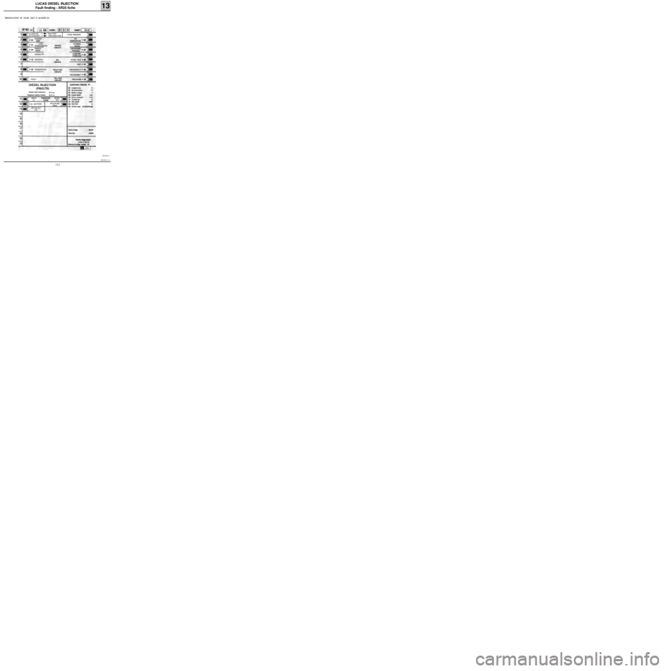
PRESENTATION OF FICHE XR25 N° 60 SIDE 1/2
FI21760-1
13-2
Page 7 of 363
DPCF01 1.0
LUCAS DIESEL INJECTION
Fault finding - XR25 fiche
13
FI21760-2
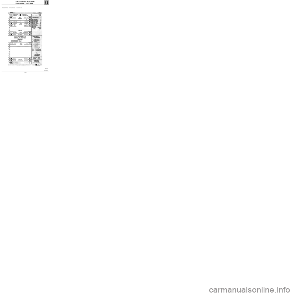
PRESENTATION OF FICHE XR25 N° 60 SIDE 2/2
13-3
Page 8 of 363
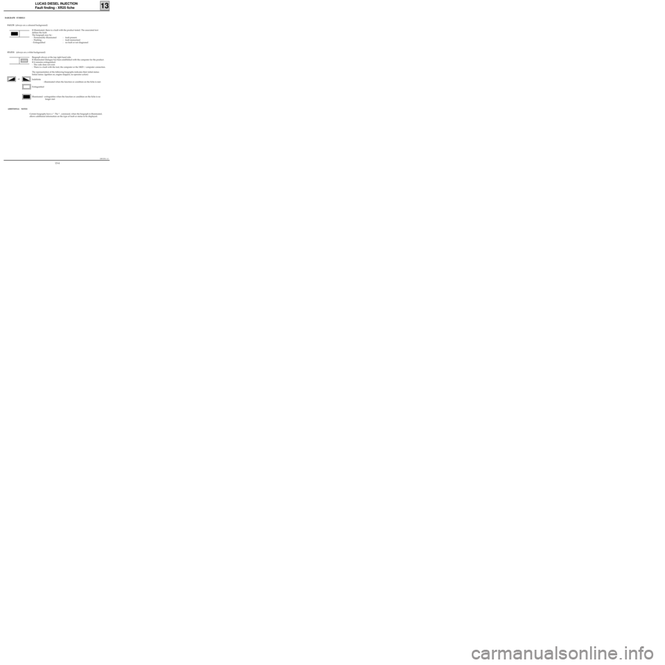
BARGRAPH SYMBOLS
FAULTS
(always on a coloured background)
If illuminated, there is a fault with the product tested. The associated text
defines the fault.
The bargraph may be :
- Permanently illuminated : fault present.
- Flashing : fault memorised
- Extinguished : no fault or not diagnosed
STATUS (always on a white background)
Bargraph always at the top right hand side.
If illuminated dialogue has been established with the computer for the product.
If it remains extinguished:
- The code does not exist.
- There is a fault with the tool, the computer or the XR25 / computer connection.
The representation of the following bargraphs indicates their initial status:
Initial status: (ignition on, engine stopped, no operator action)
Indefinite
- illuminated when the function or condition on the fiche is met.
Extinguished
Illuminated - extinguishes when the function or condition on the fiche is no
longer met
ADDITIONAL NOTES
Certain bargraphs have a *. The *.. command, when the bargraph is illuminated,
allows additional information on the type of fault or status to be displayed.
DPCF01 1.0
LUCAS DIESEL INJECTION
Fault finding - XR25 fiche
13
or
13-4
Page 9 of 363
DPCF01 1.0
LUCAS DIESEL INJECTION
Fault finding - Interpretation of XR25 bargraphs13
AFTER REPAIR
Fiche n° 60 1/2
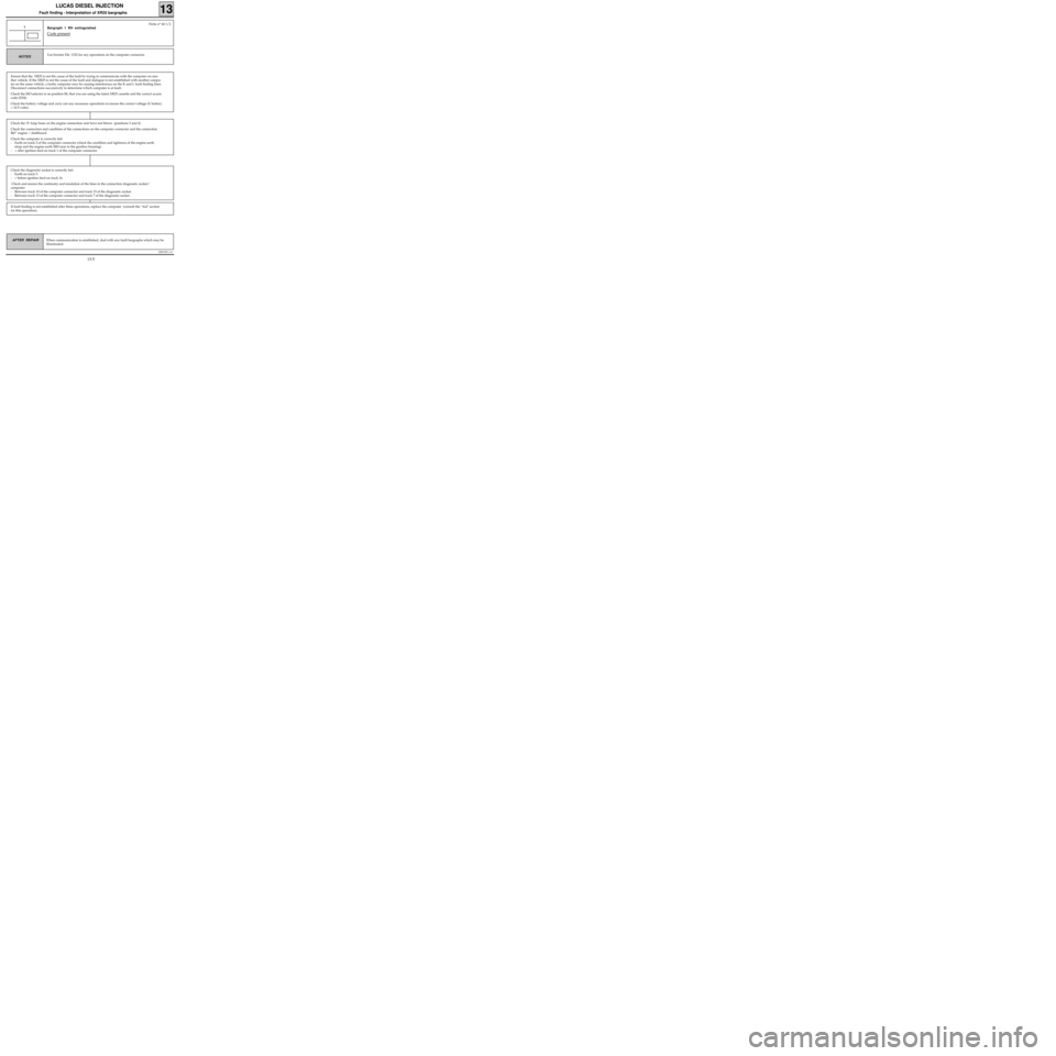
Bargraph 1 RH extinguished
Code present
1
Use bornier Elé. 1332 for any operations on the computer connector.NOTES
When communication is established, deal with any fault bargraphs which may be
illuminated.
Ensure that the XR25 is not the cause of the fault by trying to communicate with the computer on ano-
ther vehicle. If the XR25 is not the cause of the fault and dialogue is not established with another compu-
ter on the same vehicle, a faulty computer may be causing interference on the K and L fault finding lines.
Disconnect connections successively to determine which computer is at fault.
Check the ISO selector is on position S8, that you are using the latest XR25 cassette and the correct access
code (D34).
Check the battery voltage and carry out any necessary operations to ensure the correct voltage (U battery
> 10.5 volts).
Check the 15 Amp fuses on the engine connection unit have not blown (positions 3 and 4).
Check the connection and condition of the connections on the computer connector and the connection
R67 engine / dashboard.
Check the computer is correctly fed:
- Earth on track 2 of the computer connector (check the condition and tightness of the engine earth
strap and the engine earth MH near to the gearbox housing).
- + after ignition feed on track 1 of the computer connector.
Check the diagnostic socket is correctly fed:
- Earth on track 5.
- + before ignition feed on track 16.
Check and ensure the continuity and insulation of the lines in the connection diagnostic socket/
computer:
- Between track 10 of the computer connector and track 15 of the diagnostic socket.
- Between track 13 of the computer connector and track 7 of the diagnostic socket.
If fault finding is not established after these operations, replace the computer (consult the "Aid" section
for this operation).
13-5
Page 10 of 363
DPCF01 1.0
LUCAS DIESEL INJECTION
Fault finding - Interpretation of XR25 bargraphs13
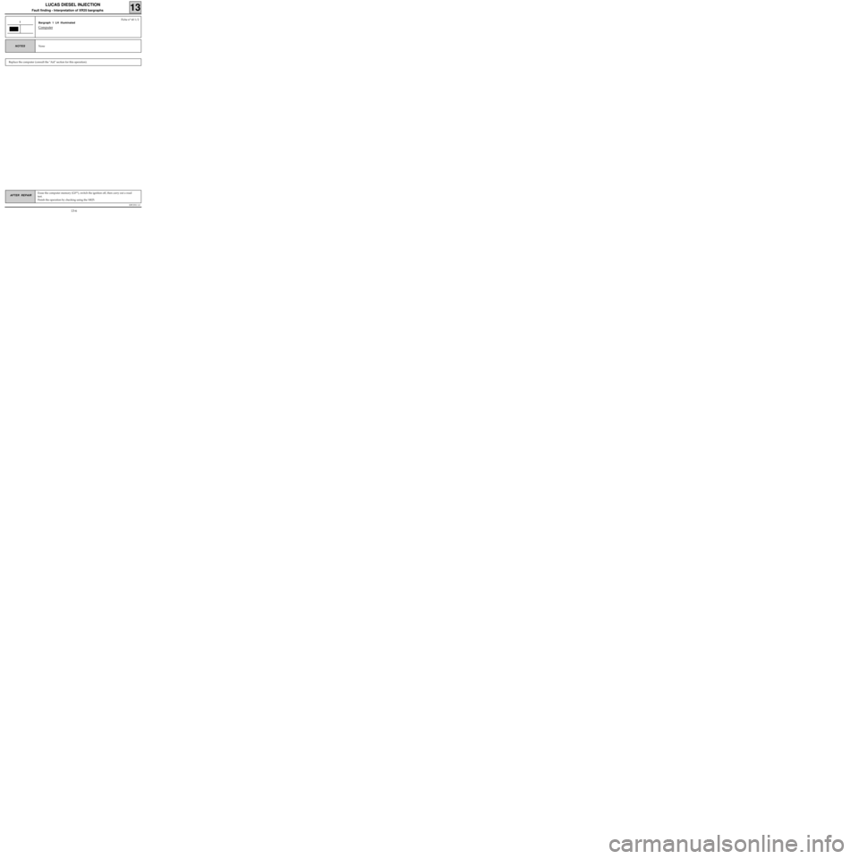
AFTER REPAIRErase the computer memory (G0**), switch the ignition off, then carry out a road
test.
Finish the operation by checking using the XR25.
Fiche n° 60 1/2
Bargraph 1 LH illuminated
Computer
1
None
NOTES
Replace the computer (consult the "Aid" section for this operation).
13-6